Lindab OLC Overflow Unit Instruction Manual
Description
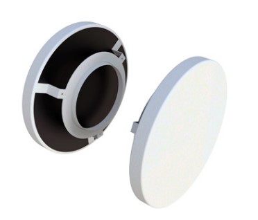
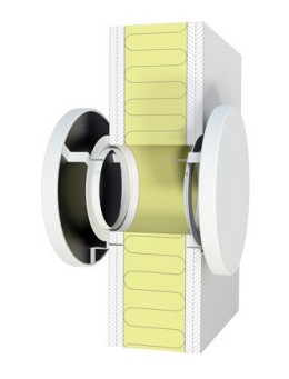
OLC is a circular overflow unit for installation directly into a wall. OLC consists of two sound-attenuating baffles, which are mounted on both sides of the wall.
- Discrete design
- Sound-attenuating baffles
Maintenance
The sound attenuation baffles on both sides of the wall can be removed to enable cleaning of internal parts.
The visible parts of the unit can be wiped with a damp cloth.
Dimensions
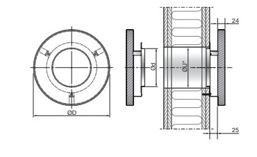
| OLC Size (Ød) | ØD
[mm] |
*ØU | m
[kg] |
| 100 | 200 | 108-110 | 0.8 |
| 125 | 250 | 133-135 | 1.0 |
| 160 | 300 | 168-170 | 1.2 |
ØU = Cutout dimension in wall = Ød + 10 mm
Quick selection
| OLC Size
Ød |
pt = 10 [Pa]
[l/s] [m3/h] |
pt = 15 [Pa]
[l/s] [m3/h] |
pt = 20 [Pa]
[l/s] [m3/h] |
*Dn,e,w [dB] | |||
| 100 | 19 | 68 | 24 | 86 | 27 | 97 | 49 |
| 125 | 28 | 101 | 34 | 122 | 39 | 140 | 47 |
| 160 | 40 | 144 | 49 | 176 | 56 | 202 | 44 |
* Values valid for cavity wall with 95 mm insulation.
Materials and finish
Installation bracket: Galvanised steel Front plate: Galvanised steel
Standard finish: Powder-coated
Standard colour: RAL 9010 or 9003, Gloss 30
The OLC is available in other colours. Please contact Lindab’s sales department for further information.
Overflow unit
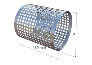
Accessories
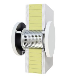
OLCZ – Perforated wall sleeve
Order code
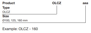
OLC installed in wall
OLC with OLCZ installed in wall
OLCZ optional accessory.
For further information, see OLC installation instruction.
Overflow unit OLC
Technical data
Capacity
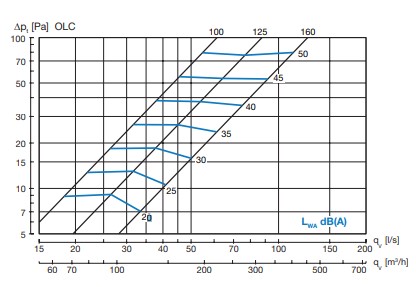
Air flow rate qv [l/s] and [m3/h], total pressure loss Δpt [Pa] and sound power level LWA [dB(A)] are specified for a OLC unit on both sides of the wall.
Dimensioning diagram
Element-normalised reduction figure Dn,e
Weighted value (Dn,e,w) evaluated according to ISO 717-1
Cavity wall with 95 mm insulation
| Size
[mm] |
125 |
Centre frequency [Hz]
250 500 1K 2K |
*Dn,e,w |
|||
| 100 | 32 | 46 | 46 | 48 | 54 | 49 |
| 125 | 34 | 43 | 43 | 46 | 51 | 47 |
| 160 | 34 | 40 | 40 | 44 | 50 | 44 |
Cavity wall with 70 mm insulation
| Size
[mm] |
125 |
Centre frequency [Hz]
250 500 1K 2K |
*Dn,e,w |
|||
| 100 | 30 | 40 | 38 | 42 | 50 | 43 |
| 125 | 30 | 37 | 37 | 42 | 49 | 43 |
| 160 | 30 | 34 | 34 | 40 | 50 | 41 |
Solid wall without insulation
| Size
[mm] |
125 |
Centre frequency [Hz]
250 500 1K 2K |
*Dn,e,w |
|||
| 100 | 24 | 24 | 23 | 32 | 40 | 31 |
| 125 | 23 | 24 | 23 | 33 | 40 | 31 |
| 160 | 24 | 24 | 23 | 32 | 39 | 30 |
Technical data Sample calculation
When dimensioning an overflow diffuser, calculate the decrease in the wall’s noise-reducing properties.
For these calculations, the area of the wall and sound reduc- tion figure R must be known.
This is adjusted in relation to the unit’s Dn,e value. Dn,e is the unit’s R value given at a transmission area of 10 m2, as speci- fied in ISO 140-10.
The D n,e value can be converted into the R value for other transmission areas using the table below.
| Area [m2] | 10 | 2 | 1 |
| Correction [dB] | 0 | -7 | -10 |
The diagram below indicates the decrease of the sound reduc- tion index of the wall, for a given octave band value (D ) or weighted value ( Dn,e,w ).
As a rough estimate the calculation can be performed directly using the wall´s Rw value and the weighted elementnormalized level difference Dn,e,w of the unit.
Example:
(See diagram below) :
Rw (wall): 50 dB
Dn,e,w (diffuser): 44 dB Rw- Dn,e,w = 6 dB Area of wall: 20 m2
Number of Units: 1 20 m2/1 = 20 m2
Indicated reduction of Rw (wall): 5 dB
Rw value for wall with unit: ~50-5 = 45 dB
The calculation can also be performed using the following for- mula:
where:
- Rres is the resulting reduction figure for wall and
- S is wall
- Dn,e is the unit’s Dn,e
- Rwall is the wall’s R value without unit.

Area of wall [m²] / Number of units [-]
Read More About This Manual & Download PDF:
Documents / Resources
 |
Lindab OLC Overflow Unit [pdf] Instruction Manual OLC Overflow Unit, OLC, Overflow Unit |
 |
Lindab OLC Overflow Unit [pdf] Instruction Manual OLC, Overflow Unit, OLC Overflow Unit, Unit |
 |
Lindab OLC Overflow Unit [pdf] Installation Guide OLCZ, OLC Overflow Unit, OLC, Overflow Unit |


