![]() Mini Meter MMU
Mini Meter MMU
(Multiple Meter Units)
Cat. No. MMT02
Installation Manual
PRODUCT DESCRIPTION
READ THESE INSTRUCTIONS BEFORE INSTALLING.
1.1 General Description
The Leviton Mini Meter is a self-powered meter that is current transformer (CT) rated electronic kilowatt-hours (kWh). It is designed for permanent connection to an electrical service. Mini Meters come in dual-element (3-wire) configuration. This guide is for use with Mini Meter Multiple Meter Units (MMUs).
1.2 Meter Features
- Revenue-grade accuracy with solid-core or easy to install split core CTs
- Built in LCD that displays total kWh and demand
- Multiple load monitoring with a single meter
- Automated Meter Reading (AMR)- compatible isolated pulse outputs
- Reverse-phase indicator
- Five year warranty
1.3 Meter Certifications
- UL Recognized Component in the US or Canada
- Certified to California Division of Measurement Standards
- Conforms to accuracy requirements set in ANSI C12.10 and C12.20
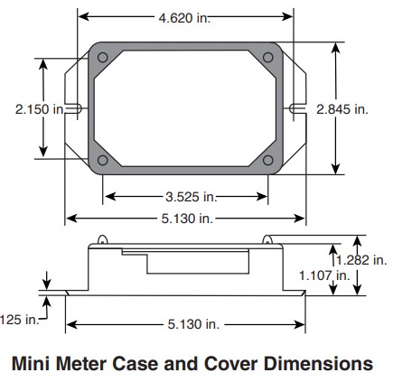
1.4 Physical Dimensions
1.4.1 Single Meter
Below shows the dimensions of a single Mini Meter case and cover.
ELECTRICAL SPECIFICATIONS
2.1 Mini Meter Specifications
Mini Meters fall under UL Circuit Category III: a device for measurements performed in the building installation. The electrical specifications for Mini Meters are given in the table below.
| Specifications | |
| Input Configurations | 1 or 2 Phase, 3 wire |
| Supply Voltage Range (L1 or L2 to Neutral) | Minimum 102VAC Maximum 138VAC |
| Maximum Input Power (L1 and L2) | 8VA |
| Maximum Rated Current | 220A primary for 200A models |
| Line Frequency | Minimum 102VAC Maximum 138VAC |
| Power Factor Range | 50-60Hz |
| Accuracy | |
| Operating Temperature Range | -22°F to 140°F (-30°C to 60°C) |
| Rated Pollution Degree | 2 |
| Rated Relative Humidity | 80% |
| Terminal Blocks: Dinkle/International Connector EK508-11P or Equivalent. |
4.4 in-lb of torque maximum |
Product approved for use with Leviton Current Transformers, rated at 200A.
NOTE:
Pollution Degree 2: Normally, only non-conductive pollution occurs. Occasionally, however, a temporary conductivity, caused by condensation, must be expected.
2.2 Input/Output Connections and User Display
| Connection Specifications | |
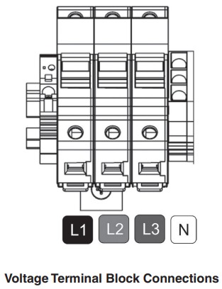
| Voltage Inputs (wire connections) | Description |
| L1 | Black wire, voltage input, Line 1, 120V with respect to neutral |
| N | White wire, Neutral input |
| L2 | Red wire, voltage input, Line 2, 120V with respect to neutral |
| CT Inputs | |
| CT1: X1 | Current Transformer input, CT1. Colored wire of CT1 |
| CT1: X2 | Current Transformer input, CT1. White wire of CT1 |
| CT2: X1 | Current Transformer input, CT2. Colored wire of CT2 |
| CT2: X2 | Current Transformer input, CT2. White wire of CT2 |
| Outputs | |
| 10, Isolated Output (10 Wh/P, Kh = 10) | Isolated pulse output: 5 watt-hours on, 5 watt-hours off, referenced to ISOL COM DO NOT USE FOR FIELD WIRING. |
| 100, Isolated Output (100 Wh/P, Kh=100) | Isolated pulse output: 50 watt-hours on, 50 watt-hours off, referenced to ISOL COM |
| 1000, Isolated Output (1 kWh/P, Kh=1000) | Isolated pulse output: 500 watt-hours on, 500 watt-hours off, referenced to ISOL COM |
| ISOL COM | Isolated common for 10/100/1000 isolated outputs |
| +12VDC | 12VDC output; current rating is 3mA maximum |
| LED/LCD Indicators | |
| Load LED (green) | The load LED has a 10Wh pulse rate (5 watt-hours on, 5 watt-hours off). The duty cycle should be 50% when the meter is connected properly, and a constant load is applied. |
|
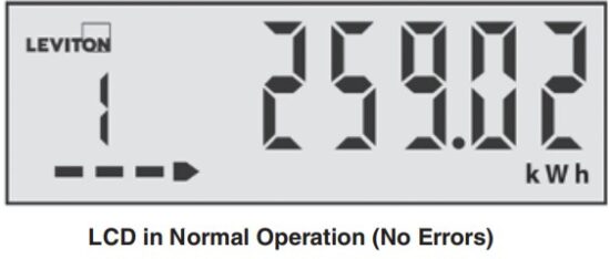
LCD |
The startup screens are displayed only once at power up. The meter repeatedly cycles through the runtime screens. Energy, demand and power are shown on the runtime screens as combined values for Line 1 and Line 2. |
 2.2.1 Using the Display to Determine Meter Status
The table below explains how errors are indicated on the LCD, listing error conditions in order of priority. If more than one error condition exists, the LCD error screen shows only the highest-priority error. If the same installation error condition exists on both lines, the LCD error screen reports the error only for Line 1, but both L1 and L2 symbols blink.
| Display Status | |||||
| Error Category | Meter Status | LCD Error Message | Bar/Arrow | L1/L2 Symbols | Determinaton of Error Condition |
| None | NORMAL | None | Animated arrow pointing right | Both off | No error or warning conditions. |
| Warning | Low Current | None | Bar and arrow indicators turned off | Blinking (one or both) | Power greater than or equal to -15W,but less than +15W. |
| Installation | Reverse Energy | Err rC1 or Err rC2 | Arrow pointing left (no blink) | Blinking (one or both) | Power less than -15W. |
| Installation | Bad Power Factor | Err PF1 or Err PF2 | Solid bar (no blink), no arrow either side | Blinking (one or both) | Checked only when current is greater than starting current level. Error when phase angle is greater than 80° and less than 90°. |
| Installation | Low Voltage | Err LU1 or Err LU2 | Solid bar (no blink), no arrow either side | Blinking (one or both) | Voltage below 102V. |
| Installation | Over Voltage | Err HU1 or Err HU2 | Solid bar (no blink), no arrow either side | Blinking (one or both) | Voltage above 138V. |
| Installation | Over Current | Err HC1 or Err HC2 | Solid bar (no blink), no arrow either side | Blinking (one or both) | Current above 110A if configured for 100A CT or 220A if configured for 200A CT. |
| Failure | Factory Service Required | FAIL 01, FAIL 02, … FAIL 05 | Blinking bar, no arrow either side | Both off | Operational error detected. |
While in a failure condition, in addition to displaying a “FAIL” code on the error screen, the screen ID (left-most digit) on every screen blinks, alternating between the screen ID and the character “F”.
If the meter reports a failure condition, contact Leviton technical assistance at 1-800-824-3005 (USA Only) or 1-800-405-5320 (Canada Only).
 CT Amperage Startup Screen, No Error Conditions
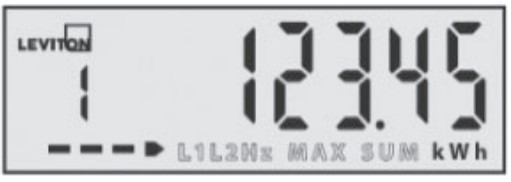 Screen 1: Real Energy, No Error Conditions
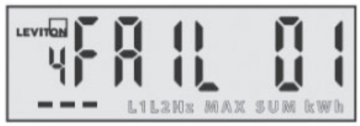 Error Screen Showing a Failure code,Factory Service Required
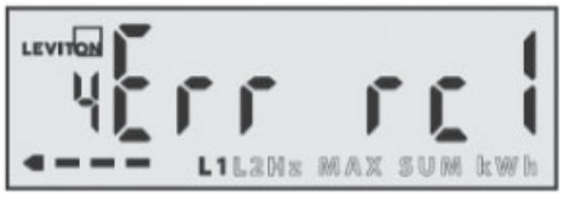 Error Screen Showing a Reverse Current Installation Error on Line 1
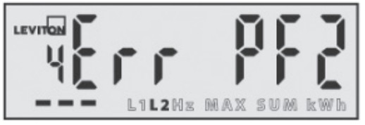 Error Screen Showing a Power Factor Installation Error on Line 2
 Error Screen Showing a Low Voltage Installation Error on Lines 1 and 2
INSTALLATION INSTRUCTIONS
3.1 WARNINGS
- TO AVOID FIRE, SHOCK OR DEATH, turn OFF all power supplying the equipment before performing any wiring operations. Use a properly rated voltage sensing device to confirm power is OFF.
- Installation of electric meters requires working with possibly hazardous voltages. These instructions are meant to be a supplement to aid trained, qualified professionals.
- Bonding is not automatic for metal conduit connections; separate bonding is to be provided.
- Installations should be done in accordance with local codes and current National Electric Code requirements.
- Equipment used in a manner not specified by this document impairs the protection provided by the equipment.
3.2 Prior to Installation
- Verify the model number and electrical specifications of the device being installed to confirm they are appropriate for the intended electrical service.
- Consult local codes for any possible permits or inspections required before beginning electrical work.
- Ensure the conduit for the installation is flexible and non-metallic. For outdoor applications, conduit and conduit fittings must be rated for UL Type 4X outdoor enclosures. Failure to use the appropriate conduit and fittings, invalidates the degree of equipment protection.
- Make sure all tools have proper insulation ratings.
- Look inside the MMU and electrical panel for possible exposed wire, broken wire, damaged components or loose connections.
3.3 What You Will Need
- Mini Meter MMU and associated mounting materials.
- Line 1, Line 2, Line 3 (where appropriate) and Neutral hook-up wires as needed for the electrical service. Wires must be 18 AWG or larger and insulated for 300 VAC minimum.
- Current Transformers (CTs): This product is designed for use with Leviton 100mA solid core (CDA02-xxx) or split core (CTD02-xxx) CTs.
- Flexible, non-metallic conduit and fittings; UL Type 4X for outdoor applications.
3.4 Mounting the Enclosure
3.4.1 Selecting a Mounting Location
MMUs require a switch or circuit breaker as part of the building installation. The switch or circuit breaker must be marked as the disconnecting device for the MMU.
It is recommended to mount the MMU near the disconnecting device in an area with adequate ventilation. Do not position the MMU where it makes it difficult to operate the disconnecting device.
Ensure that the CT and voltage lead and conduit lengths can reach the enclosure from the breaker panel. If you cannot find a mounting location near the panel, you may need to add additional inline fuses or circuit breakers in accordance with NEC regulations.
3.4.2 Drilling Conduit Holes
The shaded areas indicate appropriate drill area for conduit holes. No part of the conduit hole should extend outside of the shaded area.
3.4.3 Mounting Procedure
- Attach the mounting brackets to the back of the enclosure with the four provided screws as shown below.
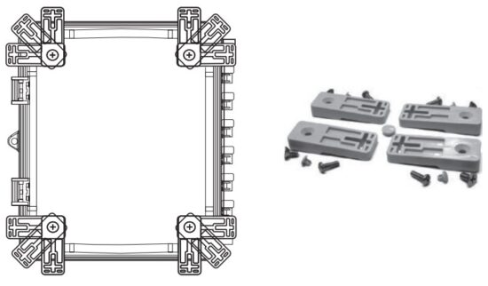
- Secure the enclosure with fasteners to the selected surface via mounting holes.
- Verify that the enclosure is not loose and that all connections are secure.
- Attach the conduit between enclosure and load center, routing wires as necessary for later use.
- Make sure the conduit fittings are aligned properly and tightened securely to prevent moisture from entering the enclosure (for outdoor applications).
3.4.4 Conduit Installation
WARNINGS:
- To reduce risk of shock or electrocution, always open or disconnect the circuit from the power distribution system of a building before installing or servicing current transformers.
- In accordance with NEC, CTs may not be installed in any panel board where they exceed 75% of the wiring space of any cross-sectional area.
NOTE: A panel schedule is highly recommended for wiring MMU internal voltage connections.
- Secure the enclosure with fasteners to the selected surface via mounting holes.
- Verify that the enclosure is not loose and that all connections are secure.
- Attach the conduit between enclosure and load center, routing wires as necessary for later use.
- Make sure the conduit fittings are aligned properly and tightened securely to prevent moisture from entering in the enclosure (outdoor applications).
- For connections to the voltage terminal block, strip wiring to approximately .300 inches and connect the wires to the appropriate terminals.
3.5 Installation of Current Transformers
WARNINGS:
- TO AVOID FIRE, SHOCK OR DEATH, make sure service is disconnected before any connections are made.
- Voltage connections must be made in accordance with NEC Section 240 and all other local electrical code requirements.
General Requirements:
- Splices on the CT leads must be within the meter enclosure, not inside the conduit. Strip the wire insulation so that the bare conductor length that connects to the meter terminal block does not exceed 0.300 inches.
- Securely fasten the CTs so that they do not slide down into live terminals. Tighten the terminal screws so that the wires are held in place, but do not to overtighten, as this may compress and weaken the conductor.
- For one- or two-phase 3-Wire electrical panels, you must install current and voltage inputs ‘in phase’ for accurate readings (for example, place CT1 on Line 1 and CT2 on Line 2).
- For three-phase 4-wire electrical panels, see Figure 12 and follow factory-provided meter schedules for correct CT locations.
Installing Solid Core CTs
- Route CT wires through the conduit if not already done.
- Trim the wire to the appropriate length to avoid coils of excess wiring.
- Strip wiring to approximately 0.300 inches and connect to the appropriate terminals, as described above.
- Turn OFF the power, disconnect each monitored conductor, and slide on a CT, ensuring the CT is correctly oriented, as noted above.
- Reconnect the conductors.
 Installing Split Core CTs
- Route CT wires through the conduit if not already done.
- Trim the wire to the appropriate length to avoid coils of excess wiring.
- Strip wiring to approximately 0.300 inches.
- Connect the CT leads to the appropriate meter, as described above.
- Turn OFF the power, place one CT around each conductor, and ensure that the white dot is facing the line side.
 Wiring the MMU


3.6 Testing the Installation
Testing Voltage
The meter LCD is active when the Mini Meter has a proper power supply. Test the voltage with an AC Voltmeter to verify that the voltage across voltage line terminals (L1 to Neutral and L2 to Neutral) does not exceed maximum voltage.
CT Reverse Phase Indicator
Each Mini Meter in the MMU enclosure has a reverse phase indicator arrow on the LCD. If any of these arrows point to the left, power down the voltage supply and verify that all CTs are installed correctly. Load LED
The load LEDs are described in section 2.3. These LEDs pulse at 50% duty cycle when the meter is connected properly and a sufficient load is applied. The load LED has a 10 Wh pulse rate (5 watt-hours on, 5 watt-hours off).
3.7 Securing the Enclosure
Testing Voltage
In accordance with safety requirements, MMUs must be secured using the provided key lock once installation is complete. The purpose of the lock is to prevent access to live parts that pose potential safety risks.
To install the lock, slide it through the provided holes on the clamp side of the enclosure and fasten securely.
WHAT TO DO IF…
Power – LCD is not ON.
- Check to make sure all connections are wired.
- Test the voltage being supplied to the meter using an AC voltmeter.
- Turn the power OFF, remove any additional line fuses, and test with ohmmeter.
Load LED does not flash.
- Verify CT connections and orientations.
- Make sure there is sufficient load to draw a significant current.
- Test the voltage being supplied to the meter using an AC voltmeter.
Registered consumption is low.
- Check to make sure the reverse phase LED is not ON
- Even if the reverse phase light is off, double-check CT orientations. One CT installed in the incorrect direction does not always illuminate the reverse phase LED.
- Make sure that current and voltage connections are in phase.
- Check power connections and fuses.
Reverse phase indicator on LCD.
- Verify orientation and connection of CT wires.
- Ensure that phasing is correct (CT1 on Line 1, CT2 on Line 2).
- Verify that a load that draws more than 1 Amp is connected to the meter.
Properly installed meters with sound connections and secure conduit fittings should not require user maintenance. If the meter is functioning abnormally, contact Leviton technical support at 1-800-824-3005 (USA Only) or 1-800-405-5320 (Canada Only).
STANDARD STATEMENTS AND WARRANTY
FCC SUPPLIER’S DECLARATION OF CONFORMITY: This device complies with part 15 of the FCC Rules. Operation is subject to the following two conditions:(1) This device may not cause harmful interference, and (2) this device must accept any interference received, including interference that may cause undesired operation. Leviton Manufacturing Co., Inc. 201 North Service Road, Melville, NY 11747. www.leviton.com.
FCC Statement: This equipment has been tested and found to comply with the limits for a Class B digital device, pursuant to part 15 of the FCC Rules. These limits are designed to provide reasonable protection against harmful interference in a residential installation. This equipment generates, uses and can radiate radio frequency energy and, if not installed and used in accordance with the instructions, may cause harmful interference to radio communications.
However, there is no guarantee that interference will not occur in a particular installation. If this equipment does cause harmful interference to radio or television reception, which can be determined by turning the equipment off and on, the user is encouraged to try to correct the interference by one or more of the following measures:
- Reorient or relocate the receiving antenna.
- Increase the separation between the equipment and receiver.
- Connect the equipment into an outlet on a circuit different from that to which the receiver is connected.
- Consult the dealer or an experienced radio/TV technician for help.
Any changes or modifications not expressly approved by Leviton Manufacturing Co., could void the user’s authority to operate the equipment.
IC Statement: This device contains license-exempt transmitter(s)/receiver(s) that comply with Innovation, Science and Economic Development Canada’s license-exempt RSS(s). Operation is subject to the following two conditions: (1) This device may not cause interference. (2) This device must accept any interference, including interference that may cause undesired operation of the device.
Leviton and the Leviton logo are the registered trademarks of Leviton Manufacturing, Co. Patents covering this product, if any, can be found on Leviton.com/patents. Leviton Manufacturing Co., Inc.
201 North Service Road, Melville, NY 11747 Visit Leviton’s website at www.leviton.com
© 2024 Leviton Manufacturing Co., Inc. All rights reserved.
Specifications and price subject to change at any time without notice.
FOR CANADA ONLY
For warranty information and/or product returns, residents of Canada should contact Leviton in writing at Leviton
Manufacturing of Canada ULC to the attention of the Quality Assurance Department, 165 Hymus Blvd,
Pointe-Claire (Quebec), Canada H9R 1E9 or by telephone at 1-800-405-5320.
LIMITED 5 YEAR WARRANTY AND EXCLUSIONS
Leviton warrants to the original consumer purchaser and not for the benefit of anyone else that this product at the time of its sale by Leviton is free of defects in materials and workmanship under normal and proper use for five years from the purchase date. Leviton’s only obligation is to correct such defects by repair or replacement, at its option. For details visit www.leviton.com or call 1-800- 824-3005. This warranty excludes and there is disclaimed liability for labor for removal of this product or reinstallation. This warranty is void if this product is installed improperly or in an improper environment, overloaded, misused, opened, abused, or altered in any manner, or is not used under normal operating conditions or not in accordance with any labels or instructions. There are no other or implied warranties of any kind, including merchantability and fitness for a particular purpose, but if any implied warranty is required by the applicable jurisdiction, the duration of any such implied warranty, including merchantability and fitness for a particular purpose, is limited to five years. Leviton is not liable for incidental, indirect, special, or consequential damages, including without limitation, damage to, or loss of use of, any equipment, lost sales or profits or delay or failure to perform this warranty obligation. The remedies provided herein are the exclusive remedies under this warranty, whether based on contract, tort or otherwise.
For Technical Assistance Call: 1-800-824-3005 (USA Only) or 1-800-405-5320 (Canada Only) www.leviton.com
![]()
Documents / Resources
 |
LEVITON MMT02 Mini Meter MMU Multiple Meter Units [pdf] Instruction Manual MMT02 Mini Meter MMU Multiple Meter Units, MMT02, Mini Meter MMU Multiple Meter Units, MMU Multiple Meter Units, Multiple Meter Units, Meter Units, Units |