TOSHIBA MCA1V-E Multi Function Sensor
Manuals+ — User Manuals Simplified.
TOSHIBA TCB-SFMCA1V-E Multi Function Sensor User Manual
Home » Toshiba » TOSHIBA TCB-SFMCA1V-E Multi Function Sensor User Manual
Thank you for purchasing the “Multi-function sensor” for TOSHIBA Air Conditioner.
Before starting the installation work, please read this manual carefully and install the product properly.
Model name: TCB-SFMCA1V-E
This product is used in combination with a heat recovery ventilation unit. Do not use the multi-function sensor on its own or in combination with other companies’ products.
Product Information
Thank you for purchasing the Multi-function sensor for TOSHIBA Air Conditioner. This product is used in combination with a heat recovery ventilation unit. Please note that it should not be used on its own or in combination with other companies’ products.
Specifications
- Model Name: TCB-SFMCA1V-E
- Product Type: Multi-function sensor (CO2 / PM)
CO2 / PM2.5 Sensor DN Code Setting List
Refer to the table below for the DN code settings and their descriptions:
| DN Co
de |
Description | SET DATA and Description |
| 560 | CO2 concentration control | 0000: Uncontrolled
0001: Controlled |
| 561 | CO2 concentration remote controller display | 0000: Hide
0001: Display |
| 562 | CO2 concentration remote controller display correction | 0000: No correction
-0010 – 0010: Remote controller display value (no correction) 0000: No correction (altitude 0 m) |
| 563 | CO2 sensor altitude correction | |
| 564 | CO2 sensor calibration function | 0000: Autocalibration enabled, Force calibration disabled
0001: Autocalibration disabled, Force calibration disabled 0002: Autocalibration disabled, Force calibration enabled |
| 565 | CO2 sensor force calibration | |
| 566 | PM2.5 concentration control | |
| 567 | PM2.5 Concentration remote controller display | |
| 568 | PM2.5 Concentration remote controller display correction | |
| 790 | CO2 target concentration | 0000: Uncontrolled
0001: Controlled |
| 793 | PM2.5 target concentration | |
| 796 | Ventilation fan speed [AUTO] fixed operation | |
| 79A | Fixed ventilation fan speed setting | |
| 79B | Concentration-controlled minimum ventilation fa n speed |
Product Usage Instructions
How to Set Each Setting
To configure the settings, follow these steps:
- Stop the heat recovery ventilation unit.
- Refer to the installation manual of the heat recovery ventilation unit (7 Installation method for each system configuration) or the installation manual of the remote controller (9. DN setting in the 7 Field setting menu) for details on how to set the DN code.
Sensor Connection Settings
To perform automatic fan speed control using the CO2 / PM2.5 sensor, change the following setting:
| DN Code | SET DATA |
| Multi-function sensor (CO2 / PM) | 0001: With connection |
FAQ
- Q: Can I use the multi function sensor on its own?
A: No, this product is designed to be used in combination with a heat recovery ventilation unit. Using it on its own may result in improper functionality. - Q: Can I use the multi function sensor with other companies’ products?
A: No, this product should only be used with TOSHIBA Air Conditioner and its specified heat recovery ventilation unit. - Q: How do I calibrate the CO2 sensor?
A: Refer to the DN code settings for CO2 sensor calibration. The manual provides options for autocalibration and force calibration.
CO2 / PM2.5 sensor DN code setting list
Refer to How to set each setting for the details of each item. Refer to the installation manual of the heat recovery ventilation unit for other DN codes.
| DN
cod e |
Description | SET DATA and description | Factory default |
| 560 | CO2 concentration control | 0000: Uncontrolled
0001: Controlled |
0001: Controlled |
|
561 |
CO2 concentration remote controller display | 0000: Hide
0001: Display |
0001: Display |
| 562 | CO2 concentration remote controller display correction | 0000: No correction
-0010 – 0010: Remote controller display value (no correction) + setting data × 50 ppm |
0000: No correction |
| 563 | CO2 sensor altitude correction | 0000: No correction (altitude 0 m)
0000 – 0040: Setting data ×100 m altitude correction |
0000: No correction (altitude 0 m) |
| 564 | CO2 sensor calibration function | 0000: Autocalibration enabled, Force calibration disabled 0001: Autocalibration disabled, Force calibration disabled 0002: Autocalibration disabled, Force calibration enabled | 0000: Autocalibration enabled, Force calibration disabled |
| 565 | CO2 sensor force calibration | 0000: No calibrate
0001 – 0100: Calibrate with setting data × 20 ppm concentration |
0000: No calibrate |
| 566 | PM2.5 concentration control | 0000: Uncontrolled
0001: Controlled |
0001: Controlled |
| 567 | PM2.5 concentration r emote controller display | 0000: Hide
0001: Display |
0001: Display |
| 568 | PM2.5 concentration remote controller display correction | 0000: No correction
-0020 – 0020: Remote controller display value (no correction) + setting data × 10 μg/m3 |
0000: No correction |
| 5F6 | Multi-function sensor ( CO2 / PM)
connection |
0000: Without connection
0001: With connection |
0000: Without connection |
| 790 | CO2 target concentration | 0000: 1000 ppm
0001: 1400 ppm 0002: 800 ppm |
0000: 1000 ppm |
| 793 | PM2.5 target concentration | 0000: 70 μg/m3
0001: 100 μg/m3 0002: 40 μg/m3 |
0000: 70 μg/m3 |
| 796 | Ventilation fan speed [ AUTO] fixed operation | 0000: Invalid (according to fan speed in remote controller settings) 0001: Valid (fixed at Fan speed [AUTO]) | 0000: Invalid (according to fan speed in remote controller settings) |
| 79A | Fixed ventilation fan speed setting | 0000: High
0001: Medium 0002: Low |
0000: High |
| 79B | Concentration-controlled minimum ventilation fan speed | 0000: Low
0001: Medium |
0000: Low |
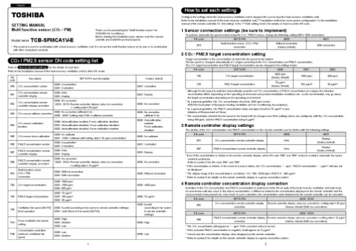
How to set each setting
Configure the settings when the heat recovery ventilation unit is stopped (Be sure to stop the heat recovery ventilation unit). Refer to the installation manual of the heat recovery ventilation unit (“7 Installation method for each system configuration”) or the installation manual of the remote controller (“9. DN setting” in the “7 Field setting menu”) for details on how to set the DN code.
Sensor connection settings (be sure to implement)
To perform automatic fan speed control using the CO2 / PM2.5 sensor, change the following setting (0001: With connection).
| DN code | SET DATA | 0000 | 0001 |
| 5F6 | Multi function sensor (CO2 / PM) connection |
Without connection (factory default) | With connection |
CO2 / PM2.5 target concentration setting
Target concentration is the concentration at which the fan speed is the highest. The fan speed is changed automatically in 7 stages according to the CO2 concentration and PM2.5 concentration. The CO2 target concentration and PM2.5 target concentration can be changed in the settings below.
| DN code | SET DATA | 0000 | 0001 | 0002 |
| 790 | CO2 target concentration | 1000 ppm (facto ry default) | 1400 ppm | 800 ppm |
| 793 | PM2.5 target concentration | 70 μg/m3 (facto ry default) | 100 μg/m3 | 40 μg/m3 |
- Although the fan speed is switched automatically using the set CO2 concentration or PM2.5 concentration as a target, the detection concentration differs depending on the operating environment and product installation conditions etc., so the concentration may go above the target concentration depending on the operating environment.
- As a general guideline, the CO2 concentration should be 1000 ppm or less. (REHVA (Federation of European Heating Ventilation and Air Conditioning Associations))
- As a general guideline, the PM2.5 concentration (daily average) should be 70 μg/m3 or less. (Ministry of Environment of China)
- The concentration at which the fan speed is the lowest will not change even if the settings above are configured, with the CO2 concentration being 400 ppm, and the PM2.5 concentration being 5 μg/m3.
Remote controller display settings
The display of the CO2 concentration and PM2.5 concentration on the remote controller can be hidden with the following settings.z
| DN code | SET DATA | 0000 | 0001 |
| 561 | CO2 concentration remote controller display | Hide | Display (factory default) |
| 567 | PM2.5 concentration remote controll er display | Hide | Display (factory default) |
- Even if the concentration is hidden in the remote controller display, when DN code “560” and “566” control is enabled, automatic fan speed control is performed. Refer to section 5 for DN code “560” and “566”.
- If the concentration is hidden, in the event of a sensor failure, the CO2 concentration “- – ppm”, PM2.5 concentration “- – μg/m3” will also notbe displayed.
- The display range of the concentration is as follows: CO2: 300 – 5000 ppm, PM2.5: 0 – 999 μg/m3.
- Refer to section 6 for details on the remote controller display in a group connection system.
Remote controller concentration display correction
Detection of the CO2 concentration and PM2.5 concentration is performed at the RA air path of the heat recovery ventilation unit main body. As unevenness will also occur in the indoor concentration, a difference between the concentration displayed in the remote controller and the environmental measurement etc. may result. In such a situation, the concentration value displayed by the remote controller can be corrected.
| DN code | SET DATA | -0010 – 0010 |
| 562 | CO2 concentration remote controller display correction | Remote controller display value (no correction) + setti ng data × 50 ppm (factory default: 0000 (no correction )) |
| DN code | SET DATA | -0020 – 0020 |
| 568 | PM2.5 concentration remote controller display correction | Remote controller display value (no correction) + setti ng data × 10 μg/m3
(factory default: 0000 (no correction)) |
- The CO2 concentration will appear as “- – ppm” if the corrected value is too low.
- If the corrected PM2.5 concentration is negative, it will appear as “0 μg/m3”.
- Correct only the concentration display value displayed by the remote controller.
- Refer to section 6 for details on the remote controller display in a group connection system.
Concentration control setting
Automatic fan speed control according to the CO2 concentration or PM2.5 concentration can be selected individually. When both controls are enabled, the unit will run at a fan speed close to the target concentration (higher of the concentrations).
| DN code | SET DATA | 0000 | 0001 |
| 560 | CO2 concentration control | Uncontrolled | Controlled (factory default) |
| 566 | PM2.5 concentration control | Uncontrolled | Controlled (factory default) |
- Both CO2 concentration control and PM2.5 concentration control are enabled in the factory default settings, so be extra careful when either control is disabled as the following faults may occur.
- If CO2 concentration control is disabled and the PM2.5 concentration is maintained at a low level, the fan speed will drop, so the indoor CO2 concentration may rise.
- If PM2.5 concentration control is disabled and the CO2 concentration is maintained at a low level, the fan speed will drop, so the indoor PM2.5 concentration may rise.
- Refer to section 6 for details on the concentration control in a group connection system.
Remote controller display and concentration control according to system configuration
- Heat recovery ventilation unit only system
(when multiple heat recovery ventilation units are connected in a group) The CO2 / PM2.5 concentration displayed on the remote controller (RBC-A*SU5*) is the concentration detected by the sensor connected to the header unit. Automatic fan speed control by sensor is only applicable to heat recovery ventilation units connected to a sensor. Heat recovery ventilation units not connected to sensors will run at a fixed ventilation fan speed setting when Fan speed [AUTO] is selected. (Refer to section 8) - When system is linked with air conditioners
The CO2 / PM2.5 concentration displayed on the remote controller (RBC-A*SU5*) is the concentration detected by the sensor connected to the heat recovery ventilation unit with the smallest indoor address. Automatic fan speed control by sensor is only applicable to heat recovery ventilation units connected to a sensor. Heat recovery ventilation units not connected to sensors will run at a fixed ventilation fan speed setting when Fan speed [AUTO] is selected. (Refer to section 8)
Minimum ventilation fan speed setting
When running under automatic fan speed control, the minimum ventilation fan speed is set as [Low] but this can be changed to [Medium]. (In this case, the fan speed is controlled at 5 levels)
| DN code | SET DATA | 0000 | 0001 |
| 79B | Concentration-controlled minimum ventilation fan speed | Low (factory default) | Medium |
Fixed fan speed setting with no sensor equipped when there is a sensor failure
In the system configuration in section 6 above, heat recovery ventilation units with no sensor equipped will run at a fixed ventilation fan speed setting when Fan speed [AUTO] is selected with the remote controller. In addition, for heat recovery ventilation units equipped with a sensor, the unit will also run at a fixed ventilation fan speed setting when the sensor performing concentration control fails (*1). This fixed ventilation fan speed setting can be set.
| DN code | SET DATA | 0000 | 0001 | 0002 |
| 79A | Fixed ventilation fan speed setting | High (factory default) | Medium | Low |
When this DN code is set to [High], the unit will run in the [High] mode even if the DN code “5D” is set to [Extra High]. If the fan speed needs to be set to [Extra High], see the installation manual of the heat recovery ventilation unit (5. Power setting for applied control) and set the DN code “750” and “754’ to 100%.
- 1 If both CO2 and PM2.5 concentration control are enabled and either sensor fails, the unit will run at automatic fan speed control with the functioning sensor.
CO2 sensor calibration function settings
The CO2 sensor uses the lowest CO2 concentration in the past 1 week as a reference value (equivalent to the general atmospheric CO2 concentration) to perform automatic calibration. When the unit is used in a location where the atmospheric CO2 concentration is always higher than the general reference value (along main roads etc.), or in an environment where the indoor CO2 concentration is always higher, the detected concentration may deviate greatly from the actual concentration due to the autocalibration effect, so either disable the automatic calibration function, or perform force calibration where necessary.
| DN code | SET DATA | 0000 | 0001 | 0002 |
| 564 | CO2 sensor automatic calibration function | Autocalibration enabled Force calibration disabled (factory default) | Autocalibration disabled Force calibration disabled | Autocalibration disabled Force calibration enabled |
| DN code | SET DATA | 0000 | 0001 – 0100 |
| 565 | CO2 sensor force calibration | No calibrate (factory default) | Calibrate with setting data × 20 ppm concentration |
For force calibration, after setting the DN code “564” to 0002, set DN code “565” to a numeric value. To perform force calibration, a measuring instrument that can measure the CO2 concentration is required separately. Run the heat recovery ventilation unit at a time period during which the CO2 concentration is stable, and quickly set the CO2 concentration value measured at the air inlet (RA) with the remote controller using the prescribed method. Force calibration is performed once only after configuration ends. Not implemented periodically.
CO2 sensor altitude correction
Correction of the CO2 concentration will be performed according to the altitude at which the heat recovery ventilation unit is installed.
| DN code | SET DATA | 0000 | 0000 – 0040 |
| 563 | CO2 sensor altitude correction | No correction (altitude 0m) (factory default) | Setting data × 100 maltitude correction |
Ventilation fan speed [AUTO] fixed operation setting
For a system that is connected to an air conditioner, Fan speed [AUTO] cannot be selected from the remote controller. By changing the DN code “796” setting, it is possible to run the heat recovery ventilation unit at Fan speed [AUTO] regardless of the fan speed set by the remote controller. In this case, take note that the fan speed will be fixed as [AUTO].
| DN code | SET DATA | 0000 | 0001 |
| 796 | Ventilation fan speed [AUTO] fixed operation | Invalid (according to fan speed in remote controller settings) (factory default) | Valid (fixed at Fan speed [AU TO]) |
List of check codes for CO2 PM2.5 sensor
Refer to the installation manual of the heat recovery ventilation unit for other check codes.
| Check cod e | Typical cause of trouble | Judging device | Check points and description |
| E30 | Indoor unit – sensor board communication trouble | Indoor | When communication between the Indoor unit and sensor boards is not possible (operation continues) |
| J04 | CO2 sensor trouble | Indoor | When a CO2 sensor trouble is detected (operation continues) |
| J05 | PM sensor trouble | Indoor | When a PM2.5 sensor trouble is detected (operation continues) |
* “Indoor” in “Judging device” refers to the heat recovery ventilation unit or the air conditioner.
Documents / Resources
TOSHIBA TCB-SFMCA1V-E Multi Function Sensor [pdf] User Manual
TCB-SFMCA1V-E Multi Function Sensor, TCB-SFMCA1V-E, Multi-Function Sensor, Function Sensor, Sensor
References
User Manual
Manuals+, Privacy Policy
This website is an independent publication and is neither affiliated with nor endorsed by any of the trademark owners. The “Bluetooth®” word mark and logos are registered trademarks owned by Bluetooth SIG, Inc. The “Wi-Fi®” word mark and logos are registered trademarks owned by the Wi-Fi Alliance. Any use of these marks on this website does not imply any affiliation with or endorsement.
Documents / Resources
 |
TOSHIBA MCA1V-E Multi Function Sensor [pdf] User Manual TCB-SFMCA1V-E Multi Function Sensor, TCB-SFMCA1V-E, Multi Function Sensor, Function Sensor, Sensor |


