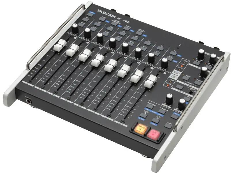
TASCAM RC-F82 Fader Unit
Introduction
- Thank you very much for purchasing the TASCAM RC-F82 Fader Unit.
- Before connecting and using the unit, please take time to read this manual thoroughly to ensure you understand how to properly set up and connect the unit, as well as the operation of its many useful and convenient functions. After you have finished reading this manual, please keep it in a safe place for future reference.
- You can also download the Owner’s Manual from the TASCAM web site (http://www.tascam.com).
Features
- Eight 100 mm faders (with dust protection) for controlling the mix or input trim level for each channel on the HS-P82 unit
- Eight rotary knobs for controlling the input trim level, mixer pan or mixer level for each channel on the HS-P82 unit
- Two rotary controls for the stereo mix (for master and solo levels)
- Eight dedicated keys for enabling/disabling SOLO and recording MUTE functions
- Eight dedicated keys for calling up channel setup screens and enabling/disabling recording
- A dedicated key for the stereo mix for calling up the L/R SETUP screen and for enabling/disabling recording
- Four direct access (shortcut) buttons to open MIXER SETUP and REMOTE SETUP screens
- Transport control functions
- Balanced XLR LINE IN connectors (STEREO)
- Balanced XLR LINE OUT 1 & 2 connectors (two stereo pairs)
- Convenient talkback functions for use in field recording environments
- Balanced XLR RETURN IN connectors for talkback functions (includes level adjustment and solo control)
- RETURN signal can be monitored using headphones
- Built-in talkback microphone; this mic’s signal can be output from the LINE OUT 2 connectors
- Headphones connector with level knob for monitoring
- Headphones monitoring can be set to STEREO, MONO, L MONO or R MONO
- Designed to be placed on top of an HS-P82 unit, the RC-F82 has the same footprint
- Connects with an HS-P82 unit by PS/2 (and is also powered by this connection)
- PS/2 external keyboard can be connected
Included items
The included items are listed below. Take care when opening the package not to damage the items. Keep the package materials for transportation in the future. Please contact the store where you purchased this unit if any of these items are missing or have been damaged during transportation.
- Fader unit (RC-F82)…………………………………………………………….1
- Connection cable (1.2m-long PS/2 cable)………………………1
- A warranty card………………………………………………………………….1
- Owner’s manual (this manual)…………………………………………1
About this manual
- In this manual, we use the following conventions:
- The names of keys and controls are given in the following typeface: MARK.
- Messages on the unit’s display are shown like this: ON
- Additional information is introduced in the styles below when needed:
- TIP
- Useful hints when using the unit.
- NOTE
- Explanation of actions in special situation and supplement.
- CAUTION
- Instructions that should be followed to avoid injury, damage to the unit or other equipment.
Trademarks
- TASCAM is a trademark of TEAC Corporation, registered in the U.S. and other countries.
- Other company names, product names and logos in this document are the trademarks or registered trademarks of their respective owners.
Precautions for placement and use
- The operating temperature should be between 0°C and 40°C (32°F and 104°F).
- Do not install in the following types of places. Doing so could degrade the sound quality and/or cause malfunctions.
- Places with significant vibrations or that are otherwise unstable
- Near windows or other places exposed to direct sunlight
- Near heaters or other extremely hot places
- Extremely cold places
- Places with bad ventilation or high humidity
- Very dusty locations
- Locations exposed directly to rain or other water
- Do not place any object on the unit.
- Avoid installing this unit on top of any heat-generating electrical device such as a power amplifier.
Beware of condensation
If the unit is moved from a cold to a warm place, or used immediately after a cold room has been heated or otherwise exposed to a sudden temperature change, condensation could occur. Should this happen, leave the unit for one or two hours before turning the unit on.
Cleaning the unit
To clean the unit, wipe it gently with a soft dry cloth. Do not wipe with chemical cleaning cloths, benzene, paint thinner, ethyl alcohol or other chemical agents to clean the unit as they could damage the surface.
Names and Functions of Parts
Top panel
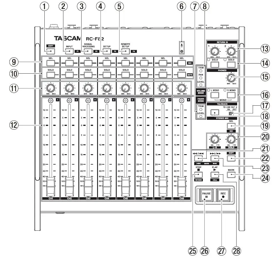
- SHIFT key
- This key works just like a shift key on a computer. It works with other keys on the unit that have blue labels. There are two SHIFT keys—one at the top left and one at the bottom right—but they have the same function.
- INPUT [F1] key
- Press this key to open the INPUT of the MIXER SETUP screen on the HS-P82’s color display. Press this key while pressing the SHIFT key to use it as the [F1] function key.
- Make function key settings on the RC-F82 of the REMOTE SETUP screen of the HS-P82 unit.
- SIGNAL PROCESSING [F2] key
- Press this key to open the SIGNAL PROCESSING of the MIXER SETUP screen on the HS-P82’s color display. Press this key while pressing the SHIFT key to use it as the [F2] function key.
- Make function key settings on the RC-F82 of the REMOTE SETUP screen of the HS-P82 unit.
- SETUP [F3] key
- Press this key to open the SETUP of the MIXER SETUP screen on the HS-P82’s color display. Press this key while pressing the SHIFT key to use it as the [F3] function key.
- Make function key settings on the RC-F82 of the REMOTE SETUP screen of the HS-P82 unit.
- REMOTE SETUP [F4] key
- Press this key to open the RC-F82 of the REMOTE SETUP screen on the HS-P82’s color display. Press this key while pressing the SHIFT key to use it as the [F4] function key.
- Make function key settings on the RC-F82 of the REMOTE SETUP screen of the HS-P82 unit.
- Built-in microphone
- Use this microphone for talkback. Press and hold the TALKBACK key to activate it.
- The TO LINE OUT 2 switch must be set to ON in order to output the signal through the LINE OUT 2/TALKBACK connectors.
- FADER MODE indicators (TRIM, LEVEL)
- These two indicators show the currently enabled fader function. TRIM indicates control over the microphone input levels, and LEVEL indicates control over the levels sent to the stereo bus.
- VOLUME MODE indicators (TRIM, PAN, LEVEL)
- These three indicators show the currently enabled volume knob function. TRIM indicates control over the microphone input levels, PAN indicates control over the stereo positions used in output to the stereo bus, and LEVEL indicates control over the levels sent to the stereo bus.
- SEL [REC] keys (CH1–CH8)
- Press one of these keys to open the channel setting (CHx SETUP) for the corresponding channel on the HS-P82’s color display. While pressing and holding the SHIFT key, press this key to enable/disable recording for the
- corresponding channel.
- SOLO [MUTE] keys (CH1–CH8)
- Press one of these keys to enable/disable soloing of that channel. While pressing and holding the SHIFT key, press this key to enable/disable record muting of that channel.
- Rotary encoder knobs (CH1–CH8)
- Use one of these knobs to adjust the microphone input level (TRIM), stereo position sent to the stereo bus (PAN) or level sent to the stereo bus (LEVEL).
- To set the functions of these knobs, select the Volume Fader Mode item on the RC-F82 of the REMOTE SETUP screen on the HS-P82 unit. The current setting can be checked with the VOLUME MODE indicators.
- CAUTION The same adjustments can be made using both this unit and the HS-P82. The adjustments made most recently will be used, regardless of which unit they were made with. For this reason, if you make an adjustment using the HS-P82 unit, the setting will differ from that last made using controls on this unit.
- Channel faders (CH1–CH8)
- Use one of these faders to adjust the microphone input (TRIM) or the level sent to the stereo bus (LEVEL) for the corresponding channel.
- To set the functions of these knobs, select the Volume Fader Mode item on the RC-F82 of the REMOTE SETUP screen on the HS-P82 unit.
- The current setting can be checked with the FADER MODE indicators.
- CAUTION The same adjustments can be made using both this unit and the HS-P82. The adjustments made most recently will be used, regardless of which unit they were made with. For this reason, if you make an adjustment using the HS-P82 unit, the setting will differ from that last made using controls on this unit.
- RETURN IN knob
- The left knob (1) adjusts the input level from the RETURN IN 1 connector, and the right knob (2) adjusts the input level from the RETURN IN 2 connector.
- RETURN IN SOLO keys/indicators (2)
- Press the left key to enable/disable soloing of the signal input from the RETURN IN 1 connector, and use the right key to enable/disable soloing of the signal input from the RETURN IN 2 connector.
- When SOLO is on, the indicator above and to the left of the button lights.
- PHONES knob
- Use this knob to adjust the volume output from the PHONES jack. Both left and right channels are adjusted simultaneously.
- CAUTION Before connecting headphones, turn the PHONES knob to the minimum volume. Failure to do so could cause sudden loud noises to occur, which might damage your hearing or equipment.
- L/R MONO keys/indicators
- Use these keys to turn ON/OFF the mono function for the left and right channels of the PHONES connector outputs. The L MONO key turns the mono function ON/OFF for the left channel, and R MONO key controls the right channel.
- When ON for a channel, the indicator above and to the left of the corresponding key lights.
- TO LINE OUT 2 switch (TALKBACK)
- When this switch is set to ON, the talkback signal is output from the LINE OUT 2/TALKBACK connectors. When OFF, the signals from the LINE IN connectors are output from them.
- TALKBACK key
- Press this key to enable talkback using the built-in microphone. When the TO LINE OUT 2 switch is ON, the signal input through the built-in mic is output from the LINE OUT 2/TALKBACK connectors.
- SEL [REC] key (STEREO MIX)
- Press this key to open the stereo channel setup screen (L/R SETUP) on the HS-P82’s color display. While pressing and holding the SHIFT key, press this key to enable/disable stereo mix (LR 2MIX) recording.
- STEREO MIX knobs (L-R, SOLO)
- Use these knobs to adjust the master level of the stereo mix.
- L-R knob
- This adjusts the master level of both left and right channels at the same time.
- SOLO knob
- This adjusts the solo level.
- CAUTION The same adjustments can be made using both this unit and the HS-P82. The adjustments made most recently will be used, regardless of which unit they were made with. For this reason, if you make an adjustment using the HS P82 unit, the setting will differ from that last made using controls on this unit.
 [MARK
[MARK  ] key
] key
- When stopped/in playback standby/during playback:
- Press briefly to skip to the beginning of the current take (file) or the previous file, and stop/continue playback standby/resume playback at the beginning of that take (file).
- Press to search backwards while pressing.
- Press this key while pressing the SHIFT key to move to the previous mark, and stop/continue playback standby/resume playback.
- This functions in the same way as the
 key on the HS-P82 unit.
- When stopped/in playback standby/during playback:
- SHIFT key
- This key works just like a shift key on a computer.
- It works with other keys on this unit that have blue labels. There are two SHIFT keys—one at the top left and one at the bottom right—but they have the same function.
 [MARK]
  key
key
- When stopped/in playback standby/during playback:
- Skip to the beginning of the next take (file), and stop/continue playback standby/resume playback at the beginning of that take (file).
- Press to search forward while pressing.
- While pressing the SHIFT key, press this key to move to the next mark, and stop/continue playback standby/resume playback.
- This functions in the same way as the
 key on the HS-P82 unit.
- When stopped/in playback standby/during playback:
- MARK key
- Press this key to add a mark at the current time. The maximum number of marks, including automatic marks, possible in a single file (take) is 99.
- This functions in the same way as the MARK key on the HS-P82 unit.
- STOP [RETAKE] key
- Press to stop recording or playback.
- Press this while pressing and holding the SHIFT key to erase the last recorded take and retake the recording.
- While recording, press this key to stop recording and stop the unit at the beginning of the last recorded file.
- This functions in the same way as the STOP [RETAKE] key on the HS-P82 unit.
- PAUSE key/indicator
- Press this key during playback to put the unit in playback standby. This key lights when in standby.
- Press this key while recording to put the unit in recording standby. This key lights when in standby.
- Press this key when the unit is stopped to put the unit in recording standby. This key lights when in standby.
- This functions in the same way as the PAUSE key on the HS-P82 unit.
- REC key/indicator
- When a recordable CF card is installed and the unit is stopped, press this key to start recording to a new file. This key lights when recording.
- When in recording standby, press this key to resume recording to a new file or the current file. This key lights when recording.
- If you press this key while recording, recording to the current file stops, but recording continues to a new file.
- This functions in the same way as the REC key on the HS-P82 unit.
- PLAY [CALL] key
- When stopped or in playback standby, press this key to start playback.
- While pressing the SHIFT key, press this to use the CALL function (locate to the point where playback was last started from standby).
- Press this key when in recording standby to start recording.
- This functions in the same way as the PLAY [CALL] key on the HS-P82 unit except it lacks a LED indicator.
Rear panel
- LINE IN connectors (left and right)
- These are balanced XLR analog input connectors (1: GND, 2: HOT, 3: COLD). Connect them with the HS-P82 LINE OUT connectors.
- LINE OUT 1 connectors (left and right)
- These are balanced XLR analog output connectors (1: GND, 2: HOT, 3: COLD). The signals input through the LINE IN connectors (left and right) are passed through and output from these.
- LINE OUT 2/TALKBACK connectors
- These are balanced XLR (left and right) analog output connectors (1: GND, 2: HOT, 3: COLD). When the TO LINE OUT 2 switch is set to OFF, the signal input through the LINE IN connectors are passed through and output from these. When the TO LINE OUT 2 switch is set to ON, the talkback signal is output from these connectors.
- RETURN IN connectors (1/2)
- These are balanced XLR analog input connectors
(1: GND, 2: HOT, 3: COLD). Use these connectors for the input of talkback signals. The signals input through these connectors are mixed in the analog domain with the signal input through the PHONES IN jack and then the mix is output through the PHONES jack.
- These are balanced XLR analog input connectors
- PHONES IN jack
- This standard stereo phone jack is an analog input connector. Connect it to the PHONES jack of the HS-P82 unit. The signal input through this connector is mixed in the analog domain with the signals input through the RETURN IN connectors and then the mix is output through the PHONES jack.
Front panel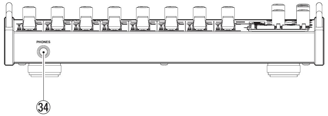
- This standard stereo phone jack is an analog input connector. Connect it to the PHONES jack of the HS-P82 unit. The signal input through this connector is mixed in the analog domain with the signals input through the RETURN IN connectors and then the mix is output through the PHONES jack.
- PHONES jack
- Use this standard stereo phone jack to connect headphones. Use the PHONES knob on the top panel to adjust the headphones output level.
- CAUTION Before connecting headphones, turn the PHONES knob to the minimum volume. Failure to do so could cause sudden loud noises to occur, which might damage your hearing or equipment.
Left side panel
- MAIN UNIT connector
- Use the included cable to connect this unit with the HS-P82 unit’s KEYBOARD connector.
- KEYBOARD connector
- Connect an IBM PC-compatible keyboard with a PS/2 interface to the unit here.
Preparations
Connecting with an HS-P82
Use the included cable to connect the MAIN UNIT connector on the left side panel of this unit with the KEYBOARD connector on the HS-P82 unit. If you want to use an external PS/2 keyboard with the HS-P82 unit, connect the keyboard to this unit’s KEYBOARD connector. 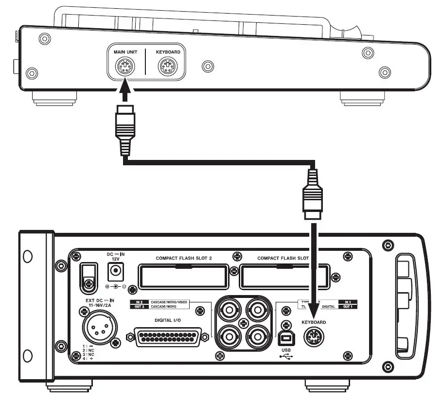
CAUTION
- Connect and disconnect the connection cable only when the HS-P82 unit power is OFF. Connecting and disconnecting the cable when the power is ON could cause damage to the HS-P82 and the fader units.
- The unit might not function properly if a PS/2 keyboard that consumes a large amount of power is used.
Connecting with other equipment
If you connect the HS-P82 unit’s LINE OUT connectors to this unit’s LINE IN connectors, you can output its signal from both the LINE OUT 1 connectors and LINE OUT 2/TALKBACK connectors on this unit. The HS-P82 unit only allowed a single line output connection, but through this unit two output connections are possible.
CAUTION When the TO LINE OUT 2 switch is ON, the HS-P82 unit’s line output signal will not be output from the LINE OUT 2/TALKBACK connectors. If you want to output the line output signal from these connectors, set this switch to OFF.
Using communication functions
- Connect the PHONES jack on the HS-P82 to the PHONES IN jack on this unit, and connect the outputs from devices that you want to receive communication from to this unit’s RETURN IN connectors. By doing this, you can monitor an analog mix of these signals through headphones connected to this unit’s PHONES jack.
- Connect the LINE OUT 2/TALKBACK connectors to the inputs on the devices that you want to communicate with and use the outputs of those devices to listen to communication from this unit’s built-in microphone.

Mixer Control Functions
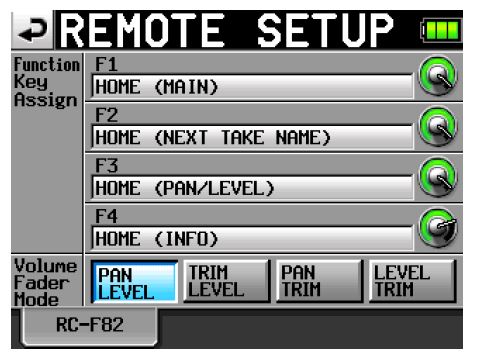
This unit has rotary controls and faders for 8 channels. The knobs can be used to adjust one of three parameters: the microphone input level (TRIM), the stereo position sent to the stereo bus (PAN) or the level sent to the stereo bus (LEVEL). The faders can be used to adjust one of two parameters: microphone input (TRIM) or the level sent to the stereo bus (LEVEL). To set this, use the Volume Fader Mode item on the RC-F82 of the HS-P82. You cannot, however, set the knobs and faders to have the same functions. To open the RC-F82 on the HS-P82 unit, press this unit’s REMOTE SETUP [F4] key or follow the procedures below.
- Press the MENU key on the HS-P82 unit to open the MENU screen.
- Press the REMOTE SETUP button to open the REMOTE SETUP screen.
- Touch the RC-F82 tab to open its.
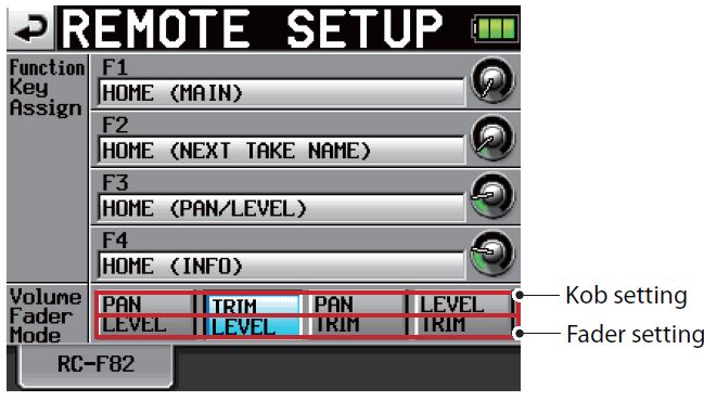
- Select a button shown next to the Volume Fader Mode item. The top line of each button shows the knob setting, and the bottom line shows the fader setting.
Button label Function TRIM Microphone input level PAN Stereo position sent to the stereo bus LEVEL Level sent to stereo bus
Knob functions
- Knobs can be set to one of three functions. The current setting can be confirmed by viewing the VOLUME MODE indicators.
TRIM (microphone input)
- Choose this setting to adjust the microphone input level. When you change the setting, the track name display area below the meters shows the gain value for a while.
- This has the same function as the input trim knobs on the front panel of the HS-P82 unit.
PAN (stereo positions sent to the stereo bus)
- Choose this setting to set the left-right stereo position sent to the stereo bus. Turn it all the way to the left to send the signal completely to the left channel. Turn it all the way to the right to send the signal completely to the right channel.
- Send it to the center to send the signal equally to both left and right channels.
- This has the same function as the PAN knob on the PAN/LVL that opens when you touch the PAN/LVL button on the Home Screen and on the CHx SETUP screens (channel setting screens where “x” is the channel number) of the HS-P82 unit.

LEVEL (level sent to the stereo bus)
- Choose this setting to adjust the level sent to the stereo bus.
- This has the same function as the 2Mix LVL knob on the PAN/LVL that opens when you touch the PAN/LVL button on the Home Screen and on the CHx SETUP screens (channel setting screens where “x” is the channel number) of the HS-P82 unit. Adjust it in a range from -∞ when turned all the way to the left and +10 dB when turned all the way to the right.
CAUTION
- The same adjustments can be made using both this unit and the HS-P82. The adjustments made most recently will be used, regardless of which unit they were made with. For this reason, if you make an adjustment using the HS-P82 unit, the setting will differ from that last made using controls on this unit.
Faders
- Faders can be set to one of two functions. The current setting can be confirmed by viewing the FADER MODE indicators.
TRIM (microphone input)
- This has the same function as the input trim knobs on the front panel of the HS-P82 unit.
- Choose this setting to adjust the microphone input level. When you change the setting, the track name display area below the meters shows the gain value for a while.
CAUTION
- When set to TRIM, the fader scale does not correspond to the trim value.
LEVEL (level sent to the stereo bus)
- This has the same function as the 2Mix LVL knob on the PAN/LVL that opens when you touch the PAN/LVL button on the Home Screen and on the CHx SETUP screens (channel setting screens where “x” is the channel number) of the HS-P82 unit. Adjust the level sent to the stereo bus in a range from -∞ to +10 dB.
CAUTION
- The same adjustments can be made using both this unit and the HS-P82. The adjustments made most recently will be used, regardless of which unit they were made with. For this reason, if you make an adjustment using the HS-P82 unit, the setting will differ from that last made using controls on this unit.
Monitoring
- You can connect headphones to the PHONES jack of this unit, as you could with the PHONES jack of the HS-P82 unit and monitor the mix as you adjust the knobs and faders.
TIP
- The PHONES jack of this unit always outputs the signals from the RETURN IN 1 and RETURN IN 2 connectors used for communication. If you only want to monitor the recording, turn the RETURN IN 1 and RETURN IN 2 knobs all the way down.
- If the SOLO key of either RETURN IN (1/2) is ON (indicator lit), the input through the PHONES IN jack is reduced –20 dB, making the monitored signal quiet. When just monitoring, turn both of these keys OFF (indicator unlit). For details, see “Listening to RETURN IN signals”.
Shortcut keys
- Each channel has SEL [REC] and SOLO [MUTE] keys that can be used for the following shortcuts. The STEREO MIX also has a SEL [REC] key that works in the same manner.
SEL [REC] keys
- Press one of these keys to open the channel setting screen (“CHx SETUP” screen) of the corresponding channel on the color display on the HS-P82 unit.
- While pressing and holding the SHIFT key, press this key for a channel to enable/disable recording on that channel.
SOLO [MUTE] keys
- Press one of these keys to enable/disable the solo function for the corresponding channel.
- While pressing and holding the SHIFT key, press this key for a channel to enable/disable the recording mute function on that channel.
- When the recording mute function is enabled, the recording level is set to -∞. If the channel is enabled for recording, silence will be recorded. The level sent to the stereo bus will also be -∞.
Direct access keys
- Use these keys to directly open of the MIXER SETUP screen on the HS-P82 unit, as well as the RC-F82 of the REMOTE SETUP screen where you can make settings for this unit. In addition, you can set how these keys function when used while pressing and holding the SHIFT key, so that you can use them to open the screens that you want directly.
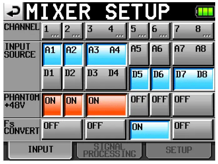
INPUT [F1] key
- Press this key to open the INPUT of the MIXER SETUP screen on the color display of the HS-P82 unit.
- Press this key while pressing the SHIFT key to use the [F1] function.
SIGNAL PROCESSING [F2] key
- Press this key to open the SIGNAL PROCESSING of the MIXER SETUP screen on the color display of the HS-P82 unit.
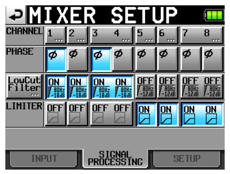
- Press this key while pressing the SHIFT key to use the [F2] function.
SETUP [F3] key
- Press this key to open the SETUP of the MIXER SETUP screen on the color display of the HS-P82 unit.
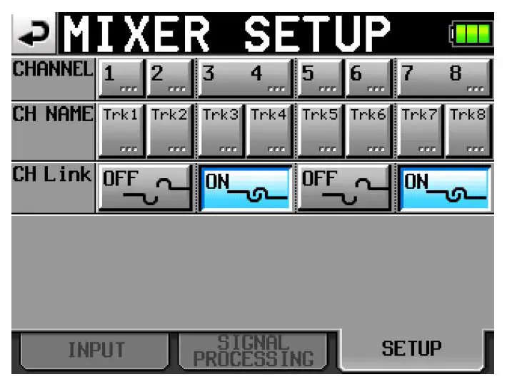
- Press this key while pressing the SHIFT key to use the [F3] function.
REMOTE SETUP [F4] key
- Press this key to open the RC-F82 of the REMOTE SETUP screen on the color display of the HS-P82 unit.
- Press this key while pressing the SHIFT key to use the [F4] function.
Function keys
- You can set each of the [F1] – [F4] function keys as shortcut keys that directly open screens on the HS-P82 unit.
- Use the Function Key Assign item on the RC-F82 of the REMOTE SETUP screen of the HS-P82 unit. The setting options are as follows.
| Setting | Functions |
| HOME (MAIN) | Opens the Home Screen |
| HOME (NEXT TAKE NAME) | Opens the NEXT TAKE NAME of the Home Screen |
| HOME (PAN/LEVEL) | Opens the PAN/LEVEL of the Home Screen |
| HOME (INFO) | Opens the INFO of the Home Screen |
| MARK LIST | Opens the MARK LIST screen |
| BATTERY | Opens the BATTERY screen |
| REC (OPTIONS) | Opens the OPTIONS of the REC SETUP screen |
| SYNC (CLOCK) | Opens the CLOCK of the SYNC T/C screen |
| SYNC (TIMECODE) | Opens the TIMECODE of the SYNC T/C screen |
| MIXER (LowCutFilter) | Opens the LOW CUT FILTER for making mixer settings |
| SYSTEM (ALARM TONE) | Opens the ALARM TONE of the SYSTEM SETUP screen |
| SLATE (MIC) | While pressing the key, the signal input through the HS-P82’s slate microphone is input to the tracks armed for recording |
| SLATE (TONE) | While pressing the key, the slate tone (built-in oscillator) signal is input to the tracks armed for recording |
Transport Control Functions
- This unit has transport keys that function in the same way as those on the HS-P82 unit for recording, playback and searching forward and backward, for example.
Recording
- Press the REC key to start recording.
- Press this key while recording, to stop recording to the current file, but continue recording to a new file without pause.
- Press the STOP [RETAKE] key to stop recording.
- While pressing and holding the SHIFT key, press the STOP [RETAKE] key to erase the last recorded take (retake function).
Playback
- Using the HS-P82 unit, select the scene that contains the take that you want to play back.
- Using the HS-P82 unit, select the take that you want to play back.
- Press the PLAY [CALL] key to start playback of that take. Press the STOP [RETAKE] key to stop playback.
- Press the PAUSE key to pause playback. The PAUSE key lights when playback is paused.
- When playback is paused, press the PLAY [CALL] key to resume playback.
- Press the
 or
or  key briefly to switch takes.
 - Press and hold the or key to search backward or forward.
- While pressing the SHIFT key, press the PLAY [CALL] key to locate to the point where playback was last started from standby (CALL function).
- NOTE The transport keys function in the same way as those on the HS-P82. For details see “4 – Recording and Playback” in the HS-P82 Owner’s Manual.
Adding marks
- Press the MARK key to create a mark at the current time. One file (take) can have a maximum of 99 marks, including automatically-created marks.
- NOTE The MARK key functions in the same way as the one on the HS-P82. For details see “7 – Mark and Locate Functions” in the HS-P82 Owner’s Manual.
Communication functions
With the built-in microphone and headphones connected to the PHONES jack, you can use this unit to communicate with remote crew. To communicate with people using other devices, connect this unit’s LINE OUT 2/TALKBACK connectors to the inputs on devices that you want to communicate through, and connect those devices’ outputs to this unit’s RETURN IN 1 and RETURN IN 2 connectors.
Communicating with the built-in microphone (TALKBACK)
The signal from the built-in microphone can be output through the LINE OUT 2/TALKBACK connectors.
- Set the TO LINE OUT 2 switch to ON.
- Speak in the direction of the built-in microphone while pressing the TALKBACK key.
- Sound input through this unit’s built-in microphone is output to the devices connected to the LINE OUT 2/TALKBACK connectors.
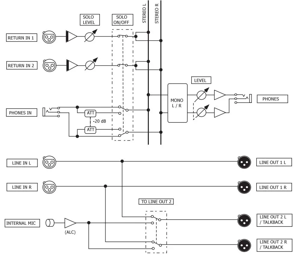
Listening to RETURN IN signals
- Sound output from devices connected to the RETURN IN 1 and RETURN IN 2 connectors is mixed with the input signal from the PHONES IN jack. This allows you to listen to communication from other devices while monitoring the recording signal.
- The signals input through the RETURN IN 1 and RETURN IN 2 connectors are adjusted separately using the RETURN IN 1 and RETURN IN 2 knobs, respectively. Each also has a SOLO key that reduces the signal input through the
- PHONES IN jack by -20 dB when ON before mixing its signal with the signals input through the RETURN IN connectors in the analog domain.
| SOLO 1 | |||
| OFF | ON | ||
| SOLO 2 | OFF | R1+R2+P | R1+P’ |
| ON | R2+P’ | R1+R2+P’ | |
- R1: RETURN IN 1input signal
- R2: RETURN IN 2 input signal
- P: PHONES IN input signal
- P’: PHONES IN input signal reduced -20 dB
Setting the headphones output (PHONES)
- The signals input through RETURN IN 1 and RETURN IN 2 connectors are mixed in the analog domain with the signal input through the PHONES IN jack and then the mix is output through the PHONES jack. Use the PHONES knob to adjust the volume.
- Use the L MONO and R MONO keys to select the mono signal of the left or right channel. When both L MONO and R MONO keys are ON, the left and right channel signals are mixed and output as a single mono signal.
Specifications
Inputs and outputs
- Inputs Analog inputsªª LINE IN connectors
- Balanced connectors: XLR-3-31 (1: GND, 2: HOT, 3: COLD)
- Nominal input level: Dependent on HS-P82 settings
- Maximum input level: Dependent on HS-P82 settings
- Pass-through to LINE OUT 1
- Pass-through to LINE OUT 2 (when TALKBACK TO LINE OUT 2 switch OFF)
- RETURN IN connectors
- Balanced connectors: XLR-3-31 (1: GND, 2: HOT, 3: COLD)
- Input impedance: 10 kΩ
- Nominal input level: +4 dBu (1.23 Vrms)
- Maximum input level: +24 dBu (12.28 Vrms)
- PHONES IN connector
- Connector: 1/4″ (6.3 mm) stereo socket
- Built-in mic
- Omni directional, monaural
Outputs
- Analog outputsªª LINE OUT 1 connectors
- Balanced connectors: XLR-3-32 (1: GND, 2: HOT, 3: COLD)
- Nominal output level: Dependent on HS-P82 settings
- Maximum output level: Dependent on HS-P82 settings
- LINE IN pass-through output
- LINE OUT 2 connectors
- (When TALKBACK TO LINE OUT 2 switch is OFF)
- Balanced connectors: XLR-3-32 (1: GND, 2: HOT, 3: COLD)
- Output impedance: Dependent on HS-P82 settings
- Nominal output level: Dependent on HS-P82 settings
- Maximum output level: Dependent on HS-P82 settings
- LINE IN pass-through output
- (when TALKBACK TO LINE OUT 2 switch ON)
- Pseudo-balanced
- Output impedance: 150Ω
- Nominal output level: –8 dBu (0.3 Vrms)
- Maximum output level: +8 dBu (2.0 Vrms)
- Internal Microphone signal is routed to this output
- PHONES connector
- Connector: 1/4″ (6.3 mm) stereo socket
- Maximum output level: 90 mW + 90 mW
- (1 kHz, THD+N 0.1%, into 32Ω)
Control input/output
- MAIN UNIT connector
- Connector: 6-pin mini-DIN socket
- KEYBOARD connector
- Connector: 6-pin mini-DIN (PS/2) socket
Other specifications
- Voltage DC 5V (supplied by the HS-P82 unit)
- Power consumption 1 W or less
- External dimensions 270 x 63 x 260 mm/10.63 x 2.48 x 10.24 in. (width x height x depth, excluding protrusions)
- Weight 2.5 kg/5.512 lb
- Operating temperature range 0 – 40° C/32 – 104°F
Dimensional drawing

- Illustrations in this manual may differ in part from the actual product.
- Specifications and the external appearance may be changed without notification to improve the product.
Block diagram
ª For U.S.A. TO THE USER
- This equipment has been tested and found to comply with the limits for a Class A digital device, pursuant to Part 15 of the FCC Rules. These limits are designed to provide reasonable protection against harmful interference when the equipment is operated in a commercial environment.
- This equipment generates, uses, and can radiate radio frequency energy and, if not installed and used in accordance with the instruction manual, may cause harmful interference to radio communications.
- Operation of this equipment in a residential area is likely to cause harmful interference in which case the user will be required to correct the interference at his own expense.
CAUTION Changes or modifications to this equipment not expressly approved by TEAC CORPORATION for compliance could void the user’s authority to operate this equipment.
This appliance has a serial number located on the bottom panel. Please record the model number and serial number and retain them for your records.
- Model number ______________________________
- Serial number ______________________________
For European Customers Disposal of electrical and electronic equipment
- (a) All electrical and electronic equipment should be disposed of separately from the municipal waste stream via designated collection facilities appointedby the government or the local authorities.
- (b) By disposing of the electrical and electronic equipment correctly, you will help save valuable resources and prevent any potential negative effects on human health and the environment.
- (c) Improper disposal of waste equipment can have serious effects on the environment and human health as a result of the presence of hazardous substances in electrical and electronic equipment.
- (d) The crossed out wheeled dust bin symbol indicates that electrical and electronic equipment must be collected and disposed of separately from household waste.

- (e) The return and collection systems are available to the end users. For more detailed information about disposal of old electrical and electronic equipment, please contact your city office, waste disposal service or the shop where you purchased the equipment.
WARNING This is a Class A product. In a domestic environment, this product may cause radio interference in which case the user may be required to take adequate measures.
CONTACT INFORMATION
- TEAC CORPORATION www.tascam.jp
- Phone: +81-42-356-9143
- 1-47 Ochiai, Tama-shi, Tokyo 206-8530, Japan
- TEAC AMERICA, INC. www.tascam.com
- Phone: +1-323-726-0303
- 7733 Telegraph Road, Montebello, California 90640 USA
- TEAC CANADA LTD. www.tascam.com
- Phone: +1905-890-8008 Facsimile: +1905-890-9888
- 5939 Wallace Street, Mississauga, Ontario L4Z 1Z8, Canada
- TEAC MEXICO, S.A. de C.V. www.teacmexico.net
- Phone: +52-55-5010-6000
- Río Churubusco 364, Colonia Del Carmen, Delegación Coyoacán, CP 04100, México DF, México
- TEAC UK LIMITED www.tascam.co.uk
- Phone: +44-8451-302511
- Suites 19 & 20, Building 6, Croxley Green Business Park, Hatters Lane, Watford, Hertfordshire, WD18 8TE, UK
- TEAC EUROPE GmbH www.tascam.de
- Phone: +49-611-71580
- Bahnstrasse 12, 65205 Wiesbaden-Erbenheim, Germany
- Printed in China
- https://muzcentre.ru/.
Documents / Resources
 |
TASCAM RC-F82 Fader Unit [pdf] Owner's Manual RC-F82 Fader Unit, RC-F82, Fader Unit, Unit |


