SmartGen DIN16A Digital Input Module User Manual
Introduction
All rights reserved. No part of this publication may be reproduced in any material form (including photocopying or storing in any medium by electronic means or other) without the written permission of the copyright holder.
Smart Gen Technology reserves the right to change the contents of this document without prior notice.
Table 1 Software Version
| Date | Version | Content |
| 2017-04-15 | 1.0 | Original release. |
| 2020-05-15 | 1.1 | Modify function descriptions of Input port. |
OVERVIEW
DIN16A digital input module is an expansion module which has 16 auxiliary digital input channels and the name of each channel can be defined by users. The input port status collected by DIN16A is transmitted to the HMC9000S controller for processing via CANBUS port.
TECHNICAL PARAMETER
Table 2 Technical Parameter.
| Item | Content |
| Working Voltage | DC18.0V~ DC35.0V continuous power supply |
| Power Consumption | <2W |
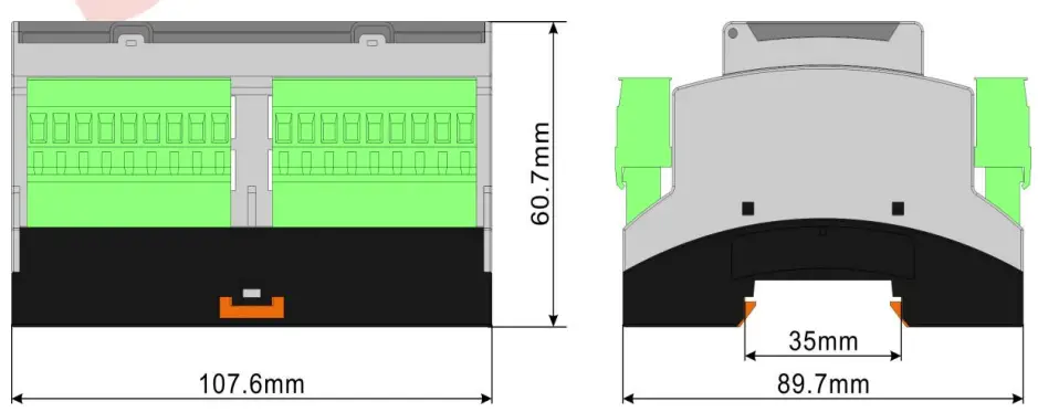
| Case Dimension | 107.6mm x 89.7mm x 60.7mm |
| Working Conditions | Temp.:(-25~+70)°C Humidity:(20~93)%RH |
| Storage Conditions | Temp.:(-25~+70)°C |
| Weight | 0.25kg |
PROTECTION
WARNING
Warnings are not shutdown alarms and do not affect the operation of the gen-set. When DIN16A module is enabled and detects the warning signal, the controller HMC9000S will initiate a warning alarm and the corresponding alarm information will be displayed on LCD.
Warning types are as follows:
Table 3 Warning Alarm List.
| No. | Items | DET Range | Description |
| 1 | DIN16A Auxiliary Input 1-16 | User-defined. | When the HMC9000S controller detects that the DIN16A auxiliary input 1-16 alarm signal and the action set as “Warning”, it will initiate a warning alarm and the corresponding alarm information will be displayed on LCD. (Each string of DIN16A input can be defined by users, such as input port 1 defined as “High Temp Warning”, when it is active, corresponding alarm information will displayed on LCD.) |
SHUTDOWN ALARM
When DIN16A module is enabled and detects the shutdown signal, the controller HMC9000S will initiate a shutdown alarm and the corresponding alarm information will be displayed on LCD.
Shutdown alarms are as follows:
Table 4 Stop Alarm List.
| No. | Items | Detection Range | Description |
| 1 | DIN16A Auxiliary Input 1-16 | User-defined. | When the HMC9000S controller detects that the DIN16A auxiliary input 1-16 alarm signal and the action set as “Shutdown”, it will initiate a shutdown alarm and the corresponding alarm information will be displayed on LCD. (Each string of DIN16A input can be defined by users, such as input port 1 defined as “High Temp Shutdown”, when it is active, corresponding alarm information will displayed on LCD.) |
PANEL CONFIGURATION
Users can set the parameters of DIN16A via HMC9000S module. Pressing and holding ![]() button for more than 3 seconds will enter the configuration menu, which allows users to set all DIN16A parameters, as follows:
button for more than 3 seconds will enter the configuration menu, which allows users to set all DIN16A parameters, as follows:
Note: Pressing  can exit setting directly during setting.
Table 5 Parameter Configuration List.
| Items | Range | Default Values | Remarks |
| 1. Input 1 Set | (0-50) | 0:Not used | DIN16A setting |
| 2. Input 1 Type | (0-1) | 0:Close to activate | DIN16A setting |
| 3. Input 2 Set | (0-50) | 0:Not used | DIN16A setting |
| 4. Input 2 Type | (0-1) | 0:Close to activate | DIN16A setting |
| 5. Input 3 Set | (0-50) | 0:Not used | DIN16A setting |
| 6. Input 3 Type | (0-1) | 0:Close to activate | DIN16A setting |
| 7. Input 4 Set | (0-50) | 0:Not used | DIN16A setting |
| 8. Input 4 Type | (0-1) | 0:Close to activate | DIN16A setting |
| 9. Input 5 Set | (0-50) | 0:Not used | DIN16A setting |
| 10. Input 5 Type | (0-1) | 0:Close to activate | DIN16A setting |
| 11. Input 6 Set | (0-50) | 0:Not used | DIN16A setting |
| 12. Input 6 Type | (0-1) | 0:Close to activate | DIN16A setting |
| 13. Input 7 Set | (0-50) | 0:Not used | DIN16A setting |
| 14. Input 7 Type | (0-1) | 0:Close to activate | DIN16A setting |
| 15. Input 8 Set | (0-50) | 0:Not used | DIN16A setting |
| 16. Input 8 Type | (0-1) | 0:Close to activate | DIN16A setting |
| 17. Input 9 Set | (0-50) | 0:Not used | DIN16A setting |
| 18. Input 9 Type | (0-1) | 0:Close to activate | DIN16A setting |
| 19. Input 10 Set | (0-50) | 0:Not used | DIN16A setting |
| 20. Input 10 Type | (0-1) | 0:Close to activate | DIN16A setting |
| 21. Input 11 Set | (0-50) | 0:Not used | DIN16A setting |
| 22. Input 11 Type | (0-1) | 0:Close to activate | DIN16A setting |
| 23. Input 12 Set | (0-50) | 0:Not used | DIN16A setting |
| 24. Input 12 Type | (0-1) | 0:Close to activate | DIN16A setting |
| 25. Input 13 Set | (0-50) | 0:Not used | DIN16A setting |
| 26. Input 13 Type | (0-1) | 0:Close to activate | DIN16A setting |
| 27. Input 14 Set | (0-50) | 0:Not used | DIN16A setting |
| 28. Input 14 Type | (0-1) | 0:Close to activate | DIN16A setting |
| 29. Input 15 Set | (0-50) | 0:Not used | DIN16A setting |
| 30. Input 15 Type | (0-1) | 0:Close to activate | DIN16A setting |
| 31. Input 16 Set | (0-50) | 0:Not used | DIN16A setting |
| 32. Input 16 Type | (0-1) | 0:Close to activate | DIN16A setting |
DEFINITION OF INPUT PORT
DEFINITION CONTENTS OF DIGITAL INPUT.
Table 6 Definition Contents List of Digital Input.
| NO. | Items | Contents | Description |
| 1 | Function set | (0-50) | More details please refer to Function Setting. |
| 2 | Active Type | (0-1) | 0:Close to activate 1:Open to activate |
| 3 | Effective Range | (0-3) | 0:From Safety on 1:From Crank 2:Always 3:Never |
| 4 | Effective Action | (0-2) | 0:Warn 1:Shutdown 2:Indication |
| 5 | Input Delay | (0-20.0)s | |
| 6 | Display string | User-defined names of input port | Input port names can be edited via PC software only. |
REAR PANEL
Panel drawing of DIN16A:
Fig.1 DIN16A Panel.
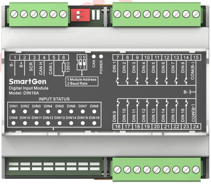
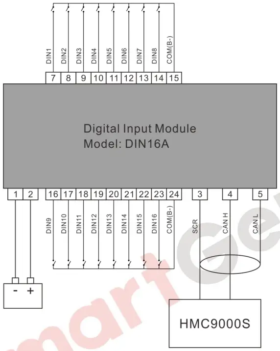
Table 7 Description of Terminal Connection.
| No. | Function | Cable Size | Description |
| 1. | DC input B- | 2.5mm2 | DC power supply negative input. |
| No. | Function | Cable Size | Description |
|
2. |
DC input B+ | 2.5mm2 | DC power supply positive input. |
|
3. |
SCR (CANBUS) | 0.5mm2 | Connect CANBUS communication port to expansion CAN port of HMC9000S. Impedance-120Ω shielding wire with its one end grounded is recommended. There is 120Ω terminal resistance inside already; if needed, make terminal 5, 6 short circuits. |
| 4. | CAN(H)(CANBUS) | 0.5mm2 | |
| 5. | CAN(L) (CANBUS) | 0.5mm2 | |
| 6. | 120Ω | 0.5mm2 | |
| 7. | DIN1 | 1.0mm2 | Digital input |
| 8. | DIN2 | 1.0mm2 | Digital input |
| 9. | DIN3 | 1.0mm2 | Digital input |
| 10. | DIN4 | 1.0mm2 | Digital input |
| 11. | DIN5 | 1.0mm2 | Digital input |
| 12. | DIN6 | 1.0mm2 | Digital input |
| 13. | DIN7 | 1.0mm2 | Digital input |
| 14. | DIN8 | 1.0mm2 | Digital input |
| 15. | COM(B-) | 1.0mm2 | Connect to B- is allowed. |
| 16. | DIN9 | 1.0mm2 | Digital input |
| 17. | DIN10 | 1.0mm2 | Digital input |
| 18. | DIN 11 | 1.0mm2 | Digital input |
| 19. | DIN 12 | 1.0mm2 | Digital input |
| 20. | DIN 13 | 1.0mm2 | Digital input |
| 21. | DIN 14 | 1.0mm2 | Digital input |
| 22. | DIN 15 | 1.0mm2 | Digital input |
| 23. | DIN 16 | 1.0mm2 | Digital input |
| 24. | COM(B-) | 1.0mm2 | Connect to B- is allowed. |
| DIP switch | SWITCH | Address selection: It is module 1 when the switch 1 is connected to terminal 12 while module 2 when connect to ON terminal.
Baud rate selection: It is 250kbps when the switch 2 is connected to terminal 12 while 125kbps when connect to ON terminal. |
|
| LED Indicator | INPUT STATUS | When DIN1~DIN16 input are active, corresponding DIN1 ~ DIN16 indicators are illuminate. |
DIN16A TYPICAL APPLICATION
Fig.2 Typical Wiring Diagram.
INSTALLATION
Fig.3 Case Dimension and Panel Cutout.
Case dimension:
FAULT FINDING
| Symptom | Possible remedy |
| Controller no response with power. | Check starting batteries; Check controller connection wirings; |
| CANBUS communication failure | Check wiring. |
| Auxiliary input alarm | Check wiring. Check if input polarities configuration is correct. |
Customer Support
SmartGen Technology Co., Ltd
No.28 Jinsuo Road, Zhengzhou, Henan Province, China
Tel: +86-371-67988888/67981888/67992951
+86-371-67981000(overseas)
Fax: +86-371-67992952
Email: sales@smartgen.cn
Web: www.smartgen.com.cn
www.smartgen.cn

Documents / Resources
 |
SmartGen DIN16A Digital Input Module [pdf] User Manual DIN16A, Digital Input Module, DIN16A Digital Input Module, Input Module, Module |