Shelly 2PM WiFi and Bluetooth 2 Channels Smart Relay Switch User Guide

Read before use
This document contains important technical and safety information about the device, its safety use and installation.
![]() CAUTION! Before beginning the installation, please read carefully and entirely this guide and any other documents accompanying the device. Failure to follow the installation procedures could lead to malfunction, danger to your health and life, violation of law or refusal of legal and/or commercial guarantee (if any). Shelly Europe Ltd. is not responsible for any loss or damage in case of incorrect installation or improper operation of this device due to failure of following the user and safety instructions in this guide.
CAUTION! Before beginning the installation, please read carefully and entirely this guide and any other documents accompanying the device. Failure to follow the installation procedures could lead to malfunction, danger to your health and life, violation of law or refusal of legal and/or commercial guarantee (if any). Shelly Europe Ltd. is not responsible for any loss or damage in case of incorrect installation or improper operation of this device due to failure of following the user and safety instructions in this guide.
Product Description
Shelly® is a line of innovative microprocessor-managed devices, which allow remote control of electric circuits through a mobile phone, tablet, PC, or home automation system.
Shelly® devices can work standalone in a local Wi-Fi network or they can also be operated through cloud home automation services. Shelly Cloud is a service that can be accessed using either an Android or iOS mobile application or with any internet browser at https://control.shelly.cloud/. Shelly® devices can be accessed, controlled, and monitored remotely from any place where the user has internet connectivity, as long as the devices are connected to a Wi-Fi router and the Internet.
Shelly® devices have an Embedded Web Interface accessible at http://192.168.33.1 when connected directly to the device access point, or at the device IP address on the local Wi-Fi network. The embedded Web Interface can be used to monitor and control the device, as well as adjust its settings.
Shelly® devices can communicate directly with other Wi-Fi devices through HTTP protocol. An API is provided by Shelly Europe Ltd.
For more information, please visit:
https://shelly-api-docs.shelly.cloud/#shelly-family-overview.
Shelly® devices are delivered with factory-installed firmware. If firmware updates are necessary to keep the devices in conformity, including security updates, Shelly Europe Ltd. will provide the updates free of charge through the device Embedded Web Interface or the Shelly mobile application, where the information about the current firmware version is available. The choice to install or not the device firmware updates is the user’s sole responsibility. Shelly Europe Ltd. shall not be liable for any lack of conformity of the device caused by failure of the user to install the provided updates in a timely manner.
Schematic
See the schematics at the beginning of the user guide.
Legend
Device terminals:
- O1: Load circuit 1 output terminal
- O2: Load circuit 1 output terminal
- S1: Switch (controlling O1) input terminal
- S2: Switch (controlling O1) input terminal
- N: Neutral terminal
- L: Live (110-240V) terminals
- +: Positive (24 VDC) terminal
 : Ground (24 VDC) terminals
Wires:
- N: Neutral wire
- L: Live wire (110 – 240 VAC)
- +: Positive (24 VDC) wire
- -: Negative (24 VDC) wire
Installation Instructions
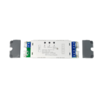
Shelly Plus 2PM (the Device) is a small form factor 2-channel smart switch which can control 2 electrical circuits, including a bi-directional AC motor. Each circuit can be loaded up to 10 A (16 A total for both circuits) and its power consumption can be measured individually (AC only).
It can be retrofitted into standard electrical wall boxes, behind power sockets and light switches or other places with limited space.
![]() CAUTION! Danger of electrocution. Mounting/installation of the Device to the power grid has to be performed with caution, by a qualified electrician.
CAUTION! Danger of electrocution. Mounting/installation of the Device to the power grid has to be performed with caution, by a qualified electrician.
![]() CAUTION! Danger of electrocution. Every change in the connections has to be done after ensuring there is no voltage present at the Device terminals.
CAUTION! Danger of electrocution. Every change in the connections has to be done after ensuring there is no voltage present at the Device terminals.
![]() CAUTION! Use the Device only with a power grid and appliances which comply with all applicable regulations. A short circuit in the power grid or any appliance connected to the Device may damage it.
CAUTION! Use the Device only with a power grid and appliances which comply with all applicable regulations. A short circuit in the power grid or any appliance connected to the Device may damage it.
![]() CAUTION! The Device must be secured by a cable protection switch in accordance with EN60898-1 (tripping characteristic B or C, max. 16 A rated current, min. 6 kA interrupting rating, energy limiting class 3). If the identification of the Neutral wire is not possible, a two-pole protection switch must be used.
CAUTION! The Device must be secured by a cable protection switch in accordance with EN60898-1 (tripping characteristic B or C, max. 16 A rated current, min. 6 kA interrupting rating, energy limiting class 3). If the identification of the Neutral wire is not possible, a two-pole protection switch must be used.
![]() CAUTION! Do not connect the Device to appliances exceeding the given max load!
CAUTION! Do not connect the Device to appliances exceeding the given max load!
![]() CAUTION! Connect the Device only in the way shown in these instructions. Any other method could cause damage and/or injury.
CAUTION! Connect the Device only in the way shown in these instructions. Any other method could cause damage and/or injury.
![]() CAUTION! Install the Device so that it is not subjected to mechanical stress.
CAUTION! Install the Device so that it is not subjected to mechanical stress.
![]() CAUTION! Do not install the Device where it can get wet.
CAUTION! Do not install the Device where it can get wet.
![]() RECOMMENDATION: Connect the Device using solid single-core cables with increased insulation heat resistance not less than PVC T105°C (221°F).
RECOMMENDATION: Connect the Device using solid single-core cables with increased insulation heat resistance not less than PVC T105°C (221°F).
Before starting the mounting/installation of the Device, check that the breakers are turned off and there is no voltage on their terminals. This can be done with a phase tester or multimeter.
When you are sure that there is no voltage, you can proceed to connecting the cables.
If you want to use the Device as a switch to control 2 load circuits, connect the Device as shown on Fig.1 for AC circuits and on Fig.2 for DC circuits.
Fig.1

Fig. 2

![]() CAUTION! Use the same power supply for the two load circuits and the Device.
CAUTION! Use the same power supply for the two load circuits and the Device.
For AC circuits connect both L terminals to the Live wire and the N terminal to the Neutral wire. Connect the first load circuits to the O1 terminal and the Neutral wire. Connect the second load circuits to the O2 terminal and the Neutral wire. Connect the first switch to the S1 terminal and the Live wire. Connect the second switch to the S2 terminal and the Live wire.
For DC circuits connect both terminals to the Negative wire and the + terminal to the Positive wire. Connect the first load circuits to the O1 terminal and the Positive wire.
Connect the second load circuits to the O2 terminal and the Positive wire. Connect the first switch to the S1 terminal and the Negative wire. Connect the second switch to the S2 terminal and the Negative wire.
![]() RECOMMENDATION: For inductive appliances that cause voltage spikes during switching on/off, such as electrical motors, fans, vacuum cleaners and similar ones, RC snubber (0.1 µF / 100 Ω / 1/2 W / 600 VAC) should be connected parallel to the appliance. The RC snubber can be purchased at
RECOMMENDATION: For inductive appliances that cause voltage spikes during switching on/off, such as electrical motors, fans, vacuum cleaners and similar ones, RC snubber (0.1 µF / 100 Ω / 1/2 W / 600 VAC) should be connected parallel to the appliance. The RC snubber can be purchased at
https://www.shelly.com/en/products/shop/rc-snubber.
As a cover controller Shelly Plus 2PM can work in 3 modes: detached, single input or dual input.
In detached mode, the Device can be controlled through its Web Interface and the App only. Even if buttons or switches are connected to the Device, they will not be allowed to control the motor rotation in detached mode.
If you want to use the Device in detached mode, connect the device as shown on Fig. 3: Connect both L terminals to the Live wire and the N terminal to the Neutral wire.
Connect the common motor terminal/wire to the Neutral wire. Connect motor direction terminals/wires to the O1 and O2 terminals.*
Fig. 3

If you want to use the Device in single input mode connect the device as shown on Fig. 4 for a button input or Fig. 5 for a switch input. Connect both L terminals to the Live wire and the N terminal to the Neutral wire. Connect the common motor terminal/wire to the Neutral wire. Connect motor direction terminals/wires to the O1 and O2 terminals*.
Fig. 4

Fig. 5

Connect the button or the switch to the S1 or the S2 terminal and the Live wire.
If the input is configured as a button in the Device settings, each button press cycles open, stop, close, stop, etc.
If the input is configured as a switch, each switch toggle cycles open, stop, close, stop, etc.
In single input mode Shelly Plus 2PM provides safety switch functionality. To utilize it, connect the device as shown on Fig.6 for a button input or Fig.7 for a switch input. Connect both L terminals to the Live wire and the N terminal to the Neutral wire. Connect the common motor terminal/wire to the Neutral wire. Connect motor direction terminals/wires to the O1 and O2 terminals*. and the Live wire. Connect the safety switch to the S2 terminal and the Live wire.
Fig.6

Fig.7

The safety switch can be configured to:
- Stop the movement until the safety switch is disengaged or until a command is sent** and, if allowed in the Device settings, the movement is resumed in the opposite direction until the end position is reached.
- Stop and immediately reverse the movement until the end position is reached. This option requires reverse movement to be allowed in the Device settings
The safety switch can also be configured to stop the movement in only one of the directions or in both.
If you want to use the Device in dual input mode, connect the Device as shown on Fig. 8 for a button inputs or Fig. 9 for a switch inputs. Connect both L terminals to the Live wire and the N terminal to the Neutral wire.
Fig. 8

Fig. 9

Connect the common motor terminal/wire to the Neutral wire.
Connect motor direction terminals/wires to the O1 and O2 terminals*.
Connect the first button/switch to the S1 terminal and the Live wire. Connect the second button/switch to the S2 terminal and the Live wire.
In case the inputs are configured as buttons:
- Pressing a button when the cover is static, moves the cover in the corresponding direction until the endpoint is reached.
- Pressing the button for the same direction while the cover is moving, stops the cover.
- Pressing the button for the opposite direction, while the cover is moving, reverses the cover movement until the endpoint is reached.
In case the inputs are configured as switches:
- Turning a switch on moves the cover in the corresponding direction until an endpoint is reached.
- Turning the switch off stops the cover movement.
If both switches are turned on, the Device will respect the last engaged switch. Turning off the last engaged switch stops the cover movement, even if the other switch is still on.
To move the cover in the opposite direction, the other switch has to be turned off and on again.
Shelly Plus 2PM can detect obstacles. If an obstacle is present, the cover movement will be stopped and, if configured so in the Device settings, reversed until the endpoint is reached.
Obstacle detection can be enabled or disabled for only one of the directions or for both.
RECOMMENDATION: To avoid voltage spikes during switching on/off the cover bi-directional motor, two RC snubbers (0.1 µF / 100 Ω / 1/2 W / 600 VAC) should be connected between the common and the two direction terminals/cables of the cover motor as shown below:

The RC snubber can be purchased at
https://www.shelly.com/en/products/shop/rc-snubber.
Initial Inclusion
If you choose to use the Device with the Shelly Smart Control mobile application and cloud service, instructions on how to connect the Device to the Cloud and control it through the Shelly Smart Control app can be found in the mobile application guide.
The Shelly mobile application and Shelly Cloud service are not conditions for the Device to function properly. This Device can be used standalone or with various other home automation platforms and protocols.
![]() CAUTION! Do not allow children to play with the buttons/ switches connected to the Device. Keep the devices for remote control of Shelly (mobile phones, tablets, PCs) away from children.
CAUTION! Do not allow children to play with the buttons/ switches connected to the Device. Keep the devices for remote control of Shelly (mobile phones, tablets, PCs) away from children.
Specification
- Dimensions (HxWxD): 37x42x16 mm / 1.46×1.65×0.63 in
- Ambient temperature: -20 °C to 40 °C / -5 °F to 105 °F
- Humidity 30 % to 70 % RH
- Max. altitude 2000 m / 6562 ft
- Power supply AC: 110 – 240 V, 50/60Hz
- Power supply DC: 24 V ±10%
- Electrical consumption: < 1.4 W
- Max switching voltage AC: 240 V
- Max switching voltage DC: 30 V
- Max switching current per channel: 10 A
- Max total switching current: 16 A
- Controlling elements: 2 relays
- Controlled elements: 2 circuits or a bi-directional AC motor
- Power metering: Yes (AC only)
- Over power protection: Yes (AC only)
- Over current protection: Yes (AC only)
- Over voltage protection: Yes (AC only)
- Over temperature Protection: Yes
- RF band: 2400 – 2495 MHz
- Max. RF power: < 20 dBm
- Wi-Fi protocol: 802.11 b/g/n
- Wi-Fi operational range (depending on local conditions):
- up to 50 m / 160 ft outdoors
- up to 30 m / 100 ft indoors”
- Bluetooth protocol: 4.2
- Bluetooth operational range (depending on local conditions):
- up to 30 m / 100 ft outdoors
- up to 10 m / 33 ft indoors
- CPU: ESP32
- Flash: 4 MB
- Schedules: 20
- Webhooks (URL actions): 20 with 5 URLs per hook
- Scripting: mJS
- MQTT: Yes
Declaration of conformity
Hereby, Shelly Europe Ltd. (former Allterco Robotics EOOD) declares that the radio equipment type Shelly Plus 2PM is in compliance with Directive 2014/53/EU, 2014/35/EU, 2014/30/ EU, 2011/65/EU.
The full text of the EU declaration of conformity is available at the following internet address:
https://shelly.link/plus2pm_DoC
Manufacturer: Shelly Europe Ltd.
Address: 103 Cherni vrah Blvd., 1407 Sofia, Bulgaria
Tel.: +359 2 988 7435
E-mail: support@shelly.cloud
Official website: https://www.shelly.com
Changes in the contact information data are published by the Manufacturer on the official website.
All rights to the trademark Shelly® and other intellectual rights associated with this Device belong to Shelly Europe Ltd.
For UK PSTI Act Statement of Compliance scan the QR code.

*The Device outputs can be reconfigured to match the required rotation direction.
**Interaction with the button, the switch or a control in the Web Interface or in the App (has to command the cover in the opposite to the direction before the safety switch engagement)
![]()

Documents / Resources
 |
Shelly 2PM WiFi and Bluetooth 2 Channels Smart Relay Switch [pdf] User Guide B4524, 2PM WiFi and Bluetooth 2 Channels Smart Relay Switch, WiFi and Bluetooth 2 Channels Smart Relay Switch, Bluetooth 2 Channels Smart Relay Switch, 2 Channels Smart Relay Switch, Smart Relay Switch, Relay Switch |