Newegg UN-102 IDE/FDD Controller
Card User Manual
Information in this manual is subject to change without notice
IBM, IBM PC/AT are trademarks or registered trademarks of International Business Machine Corp.
386 Is a trademark or registered trademark to Intel Corp.
1. INTRODUCTION
This floppy disk controller Is fully compatible with IBM PC/AT. It can be connected to two floppy disk drives. Floppy disk drives that are supported include 360KB/1.2MB(5.25’1 or 720KB/1.44MB(3.5″). The IDE hard disk controller Is an advanced design wth roost to the controller circuitry embedded inside lye hard disk itself. Such a design improves reliability, reduces power and eliminates conventional Drive-Controller compatibility problems.
The floppy disk controller can be set to primary or secondary port with jumper J4 However, your system must have a BIOS that can suppor14 floppy disk drives If you do choo a sector, dray port, The disk Cormier can be disabled with J3.
2. LAYOUT OF IDE/FDD CONTROLLER CARD

3. CABLE DESCRIPTION
3.1 FLOPPY CABLE (34-woy)

4. JUMPER SETTING

5. INSTALLATION
- Prepare your AT, 386 or compatible system. Power off the system and all related equipment.
- Remove power cord from the system (safety first) and disconnect all other cables from the system (label them ii necessary).
- Remove system unit cover for access.
- Set Jumpers on UN-102.
- Connect 34-way Floppy Disk cable to J2 (Pin 1 of cable has color strip) and connect 40- way Hard Disk cable to J1. {Pin i of cable has color strip)
- Connect Hard Disk Active LED cable to JP1 . (Pin 1 of JP1 Is closer to IC U2)
- Select a slot that is convenient for cable arrangement. Remove the screw or the back panel and pull it up.
- Align and Insert UN-102 into the slot False the screw on the back panel.
- Replace and secure the cover of the. System unit and re-connect the power cord and other externa cables.
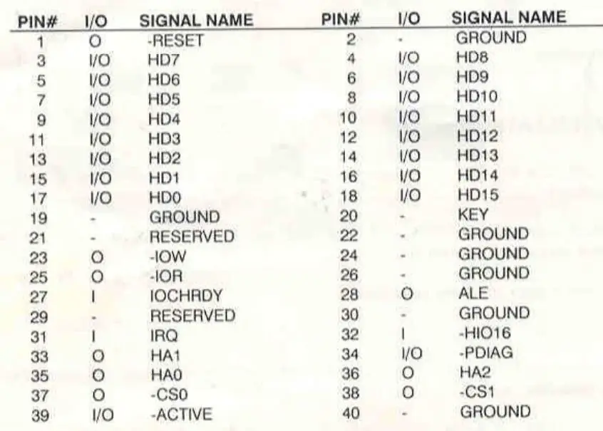
6. CONNECTOR PIN ASSIGNMENTS
6.1 FLOPPY CONNECTOR (J2)

6.2 IOE HARO DISK CONNECTOR (J1 )
6.3 Hard Disk Active LEO cable connector – JP1
Pln1 Cathode Pln2 Anode
UN-102
First Edition 7 /91
Part no. 043033
Size: 9.8 X 14.0 CM
Primed In Hong Kong
Documents / Resources
 |
Newegg UN-102 IDE/FDD Controller Card [pdf] User Manual UN-102 IDE FDD Controller Card, UN-102 IDE, FDD Controller Card, Controller Card, Card |