![]() Video Intercom
Video Intercom
INSTRUCTION MANUAL Model: INT17WSK
![]() FIRE SECURITY INTERCOM
FIRE SECURITY INTERCOM
FEATURES
- 7-inch TFT LCD screen in plastic housing
- Support 6 monitors, 2 door stations with extra 2 CCTV Cameras and 2 PIR sensors
- Missed call feature: when doorbell is not answered, a notification icon will be shown.(Note:Date/Clock feature must be activated)
- Different ringtones for Door A & Door B
- Support 32G MicroSD for pictures or video recording
- Picture memory when MicroSD card fitted (MicroSD card not supplied)
- IP65 surface mount Door Station
- Digital Photo Frame (Displays photos from MicroSD card)
- Monitoring function
- Hands-free intercom doorbell function
- Call transfer function
- Door release function
- Ten polyphonic melodies
- Ringtone volume adjustable settngs for morning / afternoon / evening
- Ring volume, talking volume, chroma and brightness adjustable
- Motion picture recording when MicroSD card installed
(MicroSD card not supplied) - Custom melody as ringtone
KIT CONTENTS
- One indoor Monitor
- One Door Station
- One adapter
- One bracket for indoor Monitor
- One angle bracket
- Accessory pack
DOOR STATION SPECIFICATION
| Camera sensor | 1/3 inch wide angle CMOS camera |
| View angle | 120° |
| Definition (Hor.) | 960P |
| LEDs for night | IR LEDs(120°) |
| Power consumption | 150mA max. |
| Power source | Supplied from indoor unit |
| Operation temp. | -40~+50ºC |
| Installation | Surface mounted |
| Lock | N/O, N/C Contact (30VDC 2A) |
| Ingress Proteclion Rating | IP65 |
| 1 | IR LEDS |
| 2 | Camera |
| 3 | Speaker |
| 4 | Call button |
| 5 | Microphone |
| 6 | Volume regulator |
| 7 | System port |
| RED | 12V DC |
| WHITE | Audio |
| BLACK | Ground |
| YELLOW | Video |
| ORANGE | Relay COM |
| GREEN | Relay N/O |
| BROWN | Relay N/C |
| BLUE | Voltage Camera + Input |
| GREY | Voltage Camera – Input |
| PURPLE | Voltage Lock + Output |
 Front of Surface mount camera INT17DS
INSTALLATION OF DOOR STATION

Door Speaker Volume Adjustment
To adjust the speaker volume of the door camera , remove the weather seal at the back of the door camera and adjust the regulator with a screwdriver. (Refer to Door Station specification for regulator location)
NOTE: Default setting of door volume is already set as HIGH. Do not overturn the volume regulator as it can be damaged easily.
INDOOR MONITOR SPECIFICATIONS

| NO | Name | Description |
| 1 | TFT display | View visitor’s image displayed on the TFT screen |
| 2 | Speaker | Sound from Door Station |
| 3 | Microphone | Transmits voice to Door Station |
| 4 | Transfer/Intercom |
Call transfer/internal intercom |
| 5 | Monitoring |
Monitoring Door 1 & 2 |
| 6 | Talk |
Start conversation with Door Station |
| 7 | Unlock |
Unlock the door lock by pressing this button |
| 8 | Setting |
Confirm/Enter to main menu |
| 9 | Unlock |
Activate Gate Unlock Relay (rear output socket) |
| 10 | Arrows |
Left / Right Navigation |
| 11 | MicroSD card slot |
For the models with MicroSD card. Insert a MicroSD card for recording |
| 12 | Status LED |
Power Indicator |
| 13 | Entry LED 1 | LED indicates the status of Door Station |
| 14 | Entry LED 2 | LED indicates the status of Door Station |
| Specification | |
| Display screen | 7” TFT LCD screen |
| Definition | 7” (1024×600 pixels) |
| CCTV camera input | AHD & CVBS only |
| Standard | PAL/NTSC |
| Calling mode | Two-way conversation |
| Calling time | 120s |
| Standby current | Maximum 250mA |
| Working current | Maximum 600mA |
| Power supply | External switching power supply (DC 12V) |
| Work temperature | 0~+50°C |
| Mounting | Surface mount |
| Picture format | JPEG standard format |
| Extension memory (Optional) | MicroSD card (maximum 32GB) (>Class 10) |
| Dimension (L x W x D) | 226 x 151 x 21.5mm |
| Digital Photo Frame | Yes (Displays photo from MicroSD Card) |
| Custom Ringtone | Yes (Uses ringtones) |
| Missed Call | Missed call indicator. Clock function needs to be activated. |
| Motion Detection | Motion picture recording when MicroSD card installed (MicroSD card not supplied) |
INSTALLATION OF INDOOR MONITOR
- Select the most suitable position where the monitor is located at user’s eye level .

![]() Keep a distance of 30cm or more from AC power to avoid electrical interference.
Keep a distance of 30cm or more from AC power to avoid electrical interference.
Avoid installation of the device near strong radiation source, eg. TV, DVR, PCs etc.
Do not drop, shake or knock the device to avoid damage to its components.
To install the indoor unit, please follow these steps as below:
![]()
INSTALLATION NOTE
Keep intercom wires more than 30cm away from AC mains power to avoid interference The electric lock is not included in the package. Use 12VDC electric strike only.
Do not exceed 500mA.
Cable Requirements
- CAT5e or CAT6 network cable connection mode:

Panacom RED BLACK WHITE YELLOW CAT5e or CAT6*** BRN, BLU BRN/WHT, BLU/ WHT GRN/ WHT,ORG/WHT GRN ORG *** Cable distance≤50 meters
- 4C ordinary unshielded and shielded wire connection mode:

- 3C ordinary unshielded +75 ohm coax video wire connection mode :

WIRING DIAGRAM
First monitor must be set as – MASTER.
All other monitors must be set as SLAVE. This can be done in the SETTINGS menu.
MONITOR ID SETTING Master= 01, Slave= 02 to 06
Note: HD Monitor can accept AHD or CVBS – analog signals. If using HD monitor with CVBS analog door station, you must reboot the monitor from the menu system after connecting the camera.
 *The first monitor is the MASTER monitor and ID must be set as Device 01. All other monitors are SLAVES and must be set as Device 02 to 06. To program the device ID go to MODE section.*
Connecting Door Camera To DVR

Please note: an additional DC 12V power supply (not supplied in kit) is required to constantly power the door camera for DVR connection.
Alarm instructions
CAM1 and CAM2 each have an alarm input. If an ALM and GND cables are shorted together, its NO-alarm will activate. The Indoor monitor will continue to ring for 120 seconds until ![]() button is pressed. The monitor will then return to Standby mode.
button is pressed. The monitor will then return to Standby mode.
For models with installed MicroSD card, an alarm will also trigger a snapshot or video recording (depending on which setting is selected). The recording time is 120 seconds, or until ![]() button is pressed. The monitor will then return to Standby mode.
button is pressed. The monitor will then return to Standby mode.
Connection diagram:
There is an alarm input for each of the two camera channels. Each alarm input can be configured to accept either a Normally Closed (NC) or Normally Open (NO) alarm inputs; or be Disabled.
A NO-alarm input will trigger an alarm event when the ALM & GND cables are shorted together. Conversely, a NC-alarm will trigger an alarm event when the ALM & GND cables are disconnected (open circuit).
OPERATION INSTRUCTIONS
VISITOR CALL
Standby Mode
 Note:
Note:
If the call buttons of both Door Stations are pressed about the same time, preference would be given to the Door Station whose call button was pressed first. Please be aware there is no indication at the second Door Station.
After the indoor monitor returns to Standby Mode, it can accept calls from the second Door Station.
Note:
The indoor monitor will automatically go into Standby Mode, if you are not at home, or have not answered the call within 60s.
![]() The Monitor will stay active for 20 seconds for the viewer to confirm that the visitor has entered the door.
The Monitor will stay active for 20 seconds for the viewer to confirm that the visitor has entered the door.
For models with a MicroSD card installed and Record function active: Recording will start from the beginning of a call, and can be manually stopped by pressing ![]() Button.
Button.
For models with a MicroSD card installed and snapshot function active: A snapshot will be taken at the start of the call. The user can also press ![]() button to take another snapshot manually.
button to take another snapshot manually.
In Monitoring mode, the monitor can listen to the door station. Press ![]() button to begin a conversation. Press
button to begin a conversation. Press ![]() button to unlock the door.
button to unlock the door.
MONITORING
By default, Door1, Door2, CAM1 and CAM2 can be monitored. To disable monitoring of Door2, set “Door2 Status” to OFF in the Mode menu. To disable monitoring of CAM1 and/or CAM2, set their corresponding “CAM1” and “CAM2” switch to OFF in the Alarm menu.
Standby Mode

If you are only using one Door Station, you can exit Monitoring mode by pressing the ![]() again (when Door2, Cam1 and Cam2 have been disabled in the menu).
again (when Door2, Cam1 and Cam2 have been disabled in the menu).
If you are using two indoor Monitors, both can simultaneously monitor the same door station. The same image will be displayed on both monitors.
If either door station calls while the user is in Monitoring mode, the monitor will ring, exit monitoring mode and display video of the new caller.
With an MicroSD card installed, the first press of ![]() button will start recording (if the recording setting is active); or will take a snapshot (if the snapshot setting is active).
button will start recording (if the recording setting is active); or will take a snapshot (if the snapshot setting is active).
CALL TRANSFER TO OTHER EXTENSION
Internal communication function requires at least two Indoor Monitors and one Door Station to be connected. Note:
Note:
After transferring a call to another extension, the first monitor will return to Standby mode. Whereas the target monitor will ring, and display video.
INTERNAL COMMUNICATION AMONG INDOOR UNITS
At least 2 indoor units are required.
Standby Mode Note:
Note:
If a visitor presses the call button of either Door Station, the Internal Communication mode will exit. The visitor’s image will be displayed with ringing. Press ![]() button to start a conversation with the visitor.
button to start a conversation with the visitor.
14.1 STANDBY MODE
There are 2 mode options during standby mode: Clock and Date mode or Digital Photo Frame mode.
14.1.1 Clock and Date Mode

14.1.2 Digital Photo Frame Mode
In Digital Photo Frame mode, the Monitor cycles through the photos in the \USER\Photo directory on the MicroSD card. Note:
Note:
- By default, the clock is displayed on standby mode. If the Digital Photo Frame is turned ON, then the images saved on the microSD card are displayed instead.
- The \USER\Photo directory on the MicroSD card must be manually created. Pictures stored in this directory will be displayed. Note: The directory name is case sensitive.
14.2 MAIN MENU
While in standby mode, press ![]() to open the Main menu. While in the Main menu (see below) press
to open the Main menu. While in the Main menu (see below) press![]() and
and ![]() to navigate through the menu. Press
to navigate through the menu. Press ![]() again to choose an item. Press
again to choose an item. Press ![]() to go back to the previous menu or Standby screen.
to go back to the previous menu or Standby screen. The Monitor will automatically return to Standby mode after 60sec of user inactivity.
14.2.1 PARAMETER SETTINGS
The System menu includes the following icons: Language, Time, System Info, Ringtone, Volume and Network Setting.
14.2.1.1 Language
The system language can be changed. In the System menu, move cursor selection to “Language”, press ![]() button to enter the “Language” menu. Press
button to enter the “Language” menu. Press ![]() button again; the arrow icons on both sides will change colour. Press
button again; the arrow icons on both sides will change colour. Press ![]() &
& ![]() to change the system language.
to change the system language. ![]() Press button again to confirm change. Then press
Press button again to confirm change. Then press ![]() button to return to previous menu.
button to return to previous menu.  14.2.1.2 Time
The Time settings adjusts the system date and time and what will be displayed in Standby mode.
Press ![]() over a highlighted item to change its setting. Use the
over a highlighted item to change its setting. Use the ![]() or
or ![]() to change its value, then press
to change its value, then press ![]() again to confirm changes. Once completed, press
again to confirm changes. Once completed, press ![]() to return to the System menu.
to return to the System menu.
- The Clock Switch controls whether the clock is displayed in Standby mode.
When turned off, the Standby screen will be all black, without a clock display.
However, the digital photo frame will still be displayed (if turned ON). - Set the display format of the clock in “Date Format”.
- The Time is displayed in 24-hour format only.

14.2.1.3 System information
Select “System Info” icon to enter the “System Information” menu. This screen shows the software version, MCU version, and microSD card free space. It includes options to Restart/ Reboot the Monitor and Format the microSD card.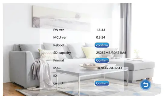 Note: Supports MicroSD cards with write speeds over 10MB/s and memory size up to 32GB.
[Restart Device]: To restart the Monitor, select “Confirm” and press ![]() . Select “Yes” to the pop-up prompt to “Reboot device?”. Otherwise, select “No” to exit the window without rebooting.
. Select “Yes” to the pop-up prompt to “Reboot device?”. Otherwise, select “No” to exit the window without rebooting.
[Format SD card]: Select “Format” button and press “Yes” to start formatting SD card. Otherwise, select “No” to cancel. NOTE: Formatting the MicroSD card will permanently remove any stored data on the MicroSD card.
Please ensure there is nothing you want to keep before formatting.
[Read]: Select this to update manufacturer device ID information from a microSD card (if directed by our Technical Support team)
14.2.1.4 Ring
This menu allows you to change the ring-tone on the monitor with an installed microSD card containing suitable ringtone files. [Mode]: There are two mode for ring-tones: “Custom” and “Default”. There are 10 default inbuilt ring-tones for selection. In the “Custom” mode, user ringtones can be selected from the “\USER\Ring” directory on the microSD card.
[Door 1 Ring]: [Door2 Ring]: Sets Default and Custom ringtones for each door station.
Use ![]() and
and ![]() &
& ![]() to adjust the two settings.
to adjust the two settings.
Change the mode to “Custom” for custom ringtones.
- Create a “\USER\Ring” directory on the microSD card. Only music stored in this ring folder can be used as Custom ringtones.
- The ringtone name must be ring_1~ring_10.
- The ringtone files must be in MP3 format.
14.2.1.5 Volume
Select “Volume” to adjust the ring volume of the monitor. Users can setup preferred ring volumes for three different times of day. Ring durations can be adjusted from 10s to 45s.
Use
![]() &
& ![]() to navigate or increase and decrease value.
to navigate or increase and decrease value. ![]() to enter.
to enter.
[Volume1]: The volume level of Ring Vol1 :01-10.
[Volume2]: The volume level of Ring Vol2:01-10.
[Volume3]: The volume level of Ring Vol3:01-10.
[Button Voice]: This turns on/off the confirmation sound when a button is pressed. 14.2.2 DIGITAL PHOTO
In the main menu, select “Photo Frame” and press to enter the Digital Photo Frame page. If the “Photo Frame” is set to ON, photos in the \USER\Photo folder on the microSD card will be displayed when in Standby mode. The photos must be in JPG format.
Note: Motion detection will be disabled if the Digital Photo Frame setting is active.
[Photo Frame]: Switches the digital photo frame mode ON or OFF. (Default is OFF)
[Play Time Interval]: Sets the display interval from 0 to 10 seconds.
The default display time is 6 seconds. 14.2.3 MODE SETTING
Select “Mode” and press ![]() to enter the “Mode” menu. Can set extension number, DOOR2 status, unlock time, recording mode, motion detection, message etc.
to enter the “Mode” menu. Can set extension number, DOOR2 status, unlock time, recording mode, motion detection, message etc.
[Set machine ID]: Choose an ID number ranging from 01-06. An ID of “01” denotes the Master Monitor. The other IDs (“02” to “06”) denote Slave Monitors.
[Door2 status]: Enable or disable the preview of Door2.
[Door1 Unlock Time]: Sets Door1 unlock time. After the unlock duration, Door1 will be locked again. The unlock time can be set from 2 to 10 seconds.
The default value is 5 seconds.
[Door2 Unlock Time]: Sets Door2 unlock time. After the unlock duration, Door2 will be locked again. The unlock time can be set from 2 to 10 seconds.
The default value is 5 seconds.
[Record mode]: Options for recording Video or taking Snapshots. For “Video”, when the call button of a Door Station is pressed, the Indoor Monitor with the MicroSD card will start recording video until the end of the call, or until ![]() is pressed. For “Snapshot”, the monitor with the MicroSD card will automatically snapshot a photo. More snapshots can be manually taken by pressing
is pressed. For “Snapshot”, the monitor with the MicroSD card will automatically snapshot a photo. More snapshots can be manually taken by pressing ![]() button.
button.
Note: Recording mode is only available for Door1, Door2.
[Motion Detection]: Options include “Door1”, “Door2”, “CAM1”, “CAM2” and “Disable” .
[Message]: Turn ON or OFF message reminder, default is ON. If a visitor calls, he/she will be prompted to leave a message if the resident is not at home or fails to answer the call.
14.2.4 ALARM
In Main Menu, move the cursor to the “Alarm” option. Then press ![]() button to enter the Alarm menu.
button to enter the Alarm menu. [Alarm Record]: for recording Video or taking Snapshots. For “Video”, when an alarm is triggered, the Indoor Monitor with the MicroSD card will automatically start recording video from the related camera until the alarm clears, or until
 ![]() is pressed. For “Snapshot”, when an alarm is triggered, the monitor with the MicroSD card will automatically take a picture from the linked camera. More snapshots can be manually taken by pressing
is pressed. For “Snapshot”, when an alarm is triggered, the monitor with the MicroSD card will automatically take a picture from the linked camera. More snapshots can be manually taken by pressing ![]() button.
button.
[Sensor Type 1]: Selects the CAM1 channel Sensor Type (see description below). When the CAM1 sensor triggers an alarm, a video recording of CAM1 will start, or a snapshot will be taken; depending on the selected recording mode. [Sensor Type 2]: Selects the CAM2 channel Sensor Type (see description below). When the CAM2 sensor triggers an alarm, a video recording of CAM2 will start, or a snapshot will be taken; depending on the selected recording mode.
[CAM1]: Enable or disable the preview of camera1
[CAM2]: Enable or disable the preview of camera2
Sensor Types:
NO: “Normally Open”, When an ALM and GND terminals are shorted together, an alarm will sound from the monitor.
NC: “Normally Closed”, When an ALM and GND terminals are disconnected, an alarm will sound from the monitor.
Disable: If an external sensor is not used, set its Sensor Type to “Disabled”.
[CAM1 ring time]: The alarm ringing time for Camera 1, after its sensor had detected an alarm. Range from 0 – 20 seconds.
[CAM2 ring time]: The alarm ringing time for Camera 2, after its sensor had detected an alarm. Range from 0 – 20 seconds.
14.2.5 MEDIA
Select “Media” and press to enter “Media” menu. It includes: Music, Photo, File Management.
TIP: Disconnect power to the Monitor before inserting or removing a MicroSD card.
This prevents electrical damage, and also ensures reliable detection of files on the microSD card. 14.2.5.1 Music (for the models with MicroSD card)
Select “Music” and press ![]() to enter music playback page. After entering music page, the first music file in the list is automatically played.
to enter music playback page. After entering music page, the first music file in the list is automatically played.
- Using a computer, create a “USER” folder and then a “Music” subfolder on the microSD card. Only MP3 music files located in the “Music” subfolder will be displayed.
Important: The “\USER\Music” directory is case sensitive. - Only the first 30 songs in the “Music” folder will be displayed.

- Use the arrow keys to select a music file. Press
 to start playback.
Press to return to previous menu.
 - Press to restart playback of the same file.
- Press and hold to bring up the Volume control.
Press &
&  to increase or decrease the volume.
Press again to save the setting. - While playing music, the playback modes can be switched. Press
 to advance to the next playback mode. The Playback Modes include: Play In Sequence, Single Play, Single Cycle, List Cycle, Random Play.
[Play In Sequence]: Play all songs from top to bottom of list.
Stop playing after the last song is played.
[Single Play]: Stop automatically after playing the current song.
[Single Cycle]: Play the same song repeatedly without stopping.
[List Cycle]: Repeat all songs in sequence. Restart playback from the first song after finishing the last song.
[Random Play]: Play all songs in random order without stopping.
Note: If a visitor pushes a door bell, or if an alarm is triggered during playback, the playback will stop and switch to door station or camera image.
14.2.5.2 Photos (for the models with MicroSD card)
Select “Photo” in the Media menu. Press ![]() to view the list of photos.
to view the list of photos.
Important: Photos must be stored in the “\USER\Photo” folder on the MicroSD card in JPG format. The directory is case sensitive.
- Press to display selected photo.
- Press & play the previous or next picture.
Pressreturn to picture list.
Note: Maximum display size of 1920 x 1080 pixels JPG files. Do not exceed this size.
14.2.5.3 File Management (for the models with MicroSD card)
Select “File Management” option, press ![]() to enter “File Management”, select SD folder, and press to enter SD card, it includes: DCIM folder, USER folder.
to enter “File Management”, select SD folder, and press to enter SD card, it includes: DCIM folder, USER folder. [Delete File]: Press the Arrow keys to highlight a file to delete. Then press and hold
 ![]() until a pop-up window appears with the message “Delete File?” Use the Arrow keys to select “Yes” and press
until a pop-up window appears with the message “Delete File?” Use the Arrow keys to select “Yes” and press ![]() to delete file. Otherwise, press
to delete file. Otherwise, press ![]() when “No” is selected to cancel.
when “No” is selected to cancel.
[DCIM]: This DCIM folder is automatically created by the Monitor for saving files created for the Record Centre. It contains the “photo” & “video” folders. The “photo” folder saves the automatic snapshots and manually captured photos. Similarly, the “video” folder saves the automatic and manually recorded videos by the monitor.
[USER]: The USER directory contains the “Music, Photo, Ring, Update” folders.
Note: These directory & names are case sensitive.
- “Music” folder stores the MP3 music files.
- “Photo” folder stores JPG pictures for the digital photo frame.
- “Ring” folder stores the custom ringtones.
- “Update” folder for upgrade files.
[Upgrade]: Put upgrade file (xxx.dd is the program file) in the update folder, select upgrade file xxx.dd and press ![]() to pop up the window “Upgrade?” Select “Yes” and press
to pop up the window “Upgrade?” Select “Yes” and press ![]() to confirm upgrade and wait for the upgrade to succeed. Or select ‘No’, and press
to confirm upgrade and wait for the upgrade to succeed. Or select ‘No’, and press ![]() to close the window.
to close the window.
[MCU Upgrade]: Put MCU file (xxx.bin is the MCU file) in the update folder, select MCU file xxx.bin and press ![]() to pop up a window “Upgrade?” Select “Yes” and press to confirm to upgrade and wait for the upgrade to succeed.
to pop up a window “Upgrade?” Select “Yes” and press to confirm to upgrade and wait for the upgrade to succeed.
Or select ‘No’ and press ![]() to close the window.
to close the window.
Note: While the system is upgrading, do not remove SD card, power off, or disable indoor monitor. After the upgrade is complete, the device will restart.
14.2.6 Record Centre (for the models with MicroSD card)
Select “Record Centre” and press ![]() to enter “Record Centre” submenu.
to enter “Record Centre” submenu.
This submenu includes video and photo icons.
To delete the videos and snapshot pictures in the Record Centre, please delete them from the DCIM folder on the microSD card.
14.2.6.1 Video Recordings
In the Recording Centre menu, select “Video” and press ![]() to show list of recorded videos.
to show list of recorded videos.
With the Arrow keys, select a video for playback, then press ![]() to start playback.
to start playback.
Note: This submenu only displays video messages recorded by the indoor Monitor.
14.2.6.2 Photo
In the Recording Centre menu, select “Photo” and press ![]() to show list of snapshot photos. With the Arrow keys, select a photo for viewing, then press
to show list of snapshot photos. With the Arrow keys, select a photo for viewing, then press ![]() to view photo. Press
to view photo. Press ![]() to return to the current menu.
to return to the current menu.
14.2.7 Colour Parameter Settings
In Standby mode, press ![]() to monitor. Press
to monitor. Press ![]() during monitoring to bring up colour adjustment mode. It includes: brightness, contrast, saturation, refresh, and return. Select the option and press
during monitoring to bring up colour adjustment mode. It includes: brightness, contrast, saturation, refresh, and return. Select the option and press ![]() . When the setting value changes its font colour, use the Arrow Keys to increase or decrease its value. Then press
. When the setting value changes its font colour, use the Arrow Keys to increase or decrease its value. Then press ![]() again to save the changes.
again to save the changes. Note: The Colour Parameters can be changed on the screens while monitoring, calling, or when in alarm.
[Bright]: Values adjustable from 0 to 50. (Default: 25).
[Contrast]: Values adjustable from 0 to 50. (Default: 25).
[Saturation]: Values adjustable from 0 to 50. (Default: 25)
[Refresh]: If Monitor has registered the wrong video format for a Door Station or camera, no video would be displayed on the Monitor. Tap “(R)” (Refresh) repeatedly to change the video signal format to match the Door Station.
[Return]: Select return, press ![]() to close colour adjustment mode.
to close colour adjustment mode.
INTELLINK WIFI INTERCOM MOBILE APP- SETUP GUIDE
A. Introduction
This section shows you how to configure the IntelLink WiFi Intercom to connect with the IntelLink app. It also shows you how to share the connection with other people (e.g. members of your household).
The screenshots in this guide are taken from an iPhone. Similar steps apply for Android phones.
B. Getting the IntelLink App
- Download the free “IntelLink” App from the Apple App Store, or the Google Play Store.
- Tap the IntelLink app icon to start the mobile app.
- Register a free account (Please use an email address as your Username)
Note: The mobile App requires access to the Internet via 3G/4G or Wireless network.
C. Preparing the IntelLink Intercom for Connection
- Power up the IntelLink Intercom
- Press to enter the Main Menu
- Press again to select the “System” icon.
- In the System menu, press & to highlight the “Network Setting” icon.
Then press to confirm selection. - Press again to choose the “Wi-Fi Set” icon.
- In the next submenu, the ‘AP-Mode’ is already selected by default.
Press twice to confirm this default selection.
The Monitor will reboot itself to enter AP-mode, and start a temporary hotspot (“Smartlife-xxxxxx”)

D. Pairing Intercom to IntelLink App (Steps for AP-mode connection)
We are now ready to connect Intercom to IntelLink App.
- In the IntelLink App, tap “Add Device”. Or tap the “+” icon on top right corner. (See Fig 1)
- In the left column, tap “Intercom”. Tap the “IntelLink WiFi Intercom” icon. (See Fig 2)
- Enter the login details of your local WiFi network, together with its password.
Then tap “Next”. (See Fig 3)
Important: Use your 2.4GHz WiFi settings, not the 5GHz band.

- Confirm “AP Mode” is shown on top right corner of App screen. Tap the small circle to left of “Confirmed IntelLink Monitor has rebooted” . Tap “Next” to continue. (See Fig 4).
- When prompted, go to the iPhone Settings, and select the Intercom’s hotspot (“SmartLife-xxxxx”) as your Wi-Fi connection. Once successful, a check mark appears against the SmartLife (Intercom) in the WiFi menu. (See Fig 5 & 6)

- Switch back to the previous IntelLink App screen, and the App should automatically start connecting with the IntelLink Intercom (and register the device online).(See Fig 7)
- If successful, the App will report “Device added successfully”. Tap “Done” to acknowledge. Congratulations, your phone is now paired with the IntelLink Intercom. (See Fig 8)
- Tap on the new ‘IntelLink Wi-Fi Intercom’ icon to test the connection. This should lead you to a control menu, which provides a Live View from the Door Station, plus other control options (e.g. to operate the door relay remotely). (See Fig 9)

E. Sharing with other users
At this point, the IntelLink modem is linked exclusively to your account only. For other users to access the Intercom remotely, you need to explicitly “share” the Intercom with other users.
There are two ways to share your access of the IntelLink Intercom: (1) Using Home Management, or (2) Direct Sharing. The following describes the Home Management approach, which is the better method; e.g. it allows all shared users to operate the door latch remotely.
- On the Main page of the IntelLink app, tap the “Me” icon on the bottom right corner. Then tap “Home Management” (See Figure 10)
- To create a new Home: Type in a New Home Name in the “Complete Home Information” page. Then tap “Save” at top-right corner. (In this example, “PSA Home” is used as the Home Name) (See Figure 11)
- Tap your new Home name (e.g. “PSA Home”), then tap “Add Member” to share with another user. (Note: Separate login accounts must first be created for every user who will be sharing access) (See Figure 12 & 13)

- Tap the ‘App Account’ icon. Then enter the pre-registered Login (email address) of a new member into the ‘Account’ field. Also enter a Name (of your choice) to identify this member.
Select the sharing permission for this user (either “Administrator” with full rights, or as “Common Member”). Tap “Save” (top-right corner) to save setting. (See Figure 14 & 15) - The App will list the new shared user, but with a pending message “Waiting to join …” To complete the sharing process, the other user must accept the share invitation through their account login. (See Figure 16)
- On the other user’s phone, ask them to log into their IntelLink app account.
Then tap “Me” and “Home Management”. And there should be an invitation message to join the new Home. Tap “Accept” to confirm invitation. Tap ‘Home’ to return to the Main Page. Then tap top left corner to select the newly accepted Home Name. The IntelLink Intercom will appear in their account, with the assigned rights to access the Intercom. (See Figure 17 to 20) - Congratulations! You have successfully shared the IntelLink Intercom with another user. To add more shared users, simply repeat above steps through your App login.

WARRANTY & LIABILITY
- PSA Products Pty Ltd (ABN: 99 076 468 703) of 17 Millicent Street, Burwood 3125 Victoria, Australia warrants this product for a period of 24 months from the date of purchase, as reflected on the Authorised Resellers or Distributors invoice/ receipt provided to you. PSA Products pty Ltd will repair or replace the product (at the option of PSA Products) due to any manufacturing defect, at the cost of PSA Products pty Ltd (excluding any labour costs relating to removal or re-installation of product, and transport costs).
- This warranty shall not apply to the product if it has been damaged, modified, abused or altered after the date of purchase, or if it fails to operate due to improper maintenance.
- To the extent permitted by law, the liability of PSA Products Pty Ltd arising from the sale or under the terms of this limited warranty shall not in any case exceed the cost of replacement and subject to this clause. In no case shall PSA Products pty Ltd be liable for consequential loss or damages resulting from the failure of the product or breach of this, or: Any other warranty, express or implied, loss or damage caused by failure to abide by the instructions supplied in the leaflets.
- To the extent permitted by law, PSA Products Pty Ltd., makes no warranty, expressed or implied, written or oral, including that of merchantability or fitness for any particular purpose, with respect to the consumer replaceable battery if any. A product with nonserviceable built-in battery is covered under warranty of the product as per point 1.
- This warranty is provided in addition to other rights and remedies you have under law: Our goods come with guarantees that cannot be excluded under the Australian Consumer Law. You are entitled to a replacement or refund for a major failure and compensation for any other reasonably foreseeable loss or damage. You are also entitled to have the goods repaired or replaced if the goods fail to be of acceptable quality and the failure does not amount to a major failure. What constitutes a major failure is set out in the Australian Consumer Law.
- To make a claim under warranty, take the product (with a proof of purchase) to the store where you purchased the product or contact PSA Products Pty Ltd. Phone (03) 9888 9889. or Email: enquiry@psaproducts.com.au with details, proof of purchase or expense claim in writing.
![]() 17 Millicent Street, Burwood, VIC 3125 Australia
17 Millicent Street, Burwood, VIC 3125 Australia
Tel: 1300 PSA PRODUCTS (1300 772 776)
Fax: (03) 9888 9993
enquiry@psaproducts.com.au
psaproducts.com.au
Documents / Resources
 |
IntelLink INT17WSK Video Intercom System Kit [pdf] Instruction Manual INT17WSK, INT17WSK Video Intercom System Kit, Video Intercom System Kit, Intercom System Kit |
 |
IntelLink INT17WSK Video Intercom [pdf] Instruction Manual INT17WSK Video Intercom, INT17WSK, Video Intercom, Intercom |


