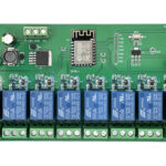
Elsay ESP8266 Wi-Fi Single 30A Relay Module

Specifications
- Product Name: Elsay ESP8266 WIFI Single 30A Relay Module
- Power Supply: DC7-80V/5V
- WiFi Module: ESP-12F
- Board Size: 78 x 47mm
- Weight: 45g
Product Usage Instructions
Functional Features
The Elsay ESP8266 single 30A relay development board is suitable for ESP8266 secondary development learning, smart home wireless control, and other applications. It comes with Arduino development environment reference code.
Hardware Introduction and Description
Interface Introduction
- Burning Port: GND, RX, TX, 5V of ESP8266 are connected to GND, TX, RX, 5V of the external TTL serial module respectively. IO0 needs to be connected to GND when downloading.
- Relay Output: NC (normally closed terminal), COM (common terminal), NO (normally open terminal).
GPIO Pinout Ports
- ADC, EN, IO16, IO14, IO12, IO2, IO15, GPIO16, GPIO14, GPIO12, TXD, RXD, GND, IO13, GPIO13, 5V, IO5, 3.3V, IO4, RY1, IO0
Arduino Development Environment Setup
- Install Arduino IDE 1.8.9 or the latest version.
- Open Arduino IDE, go to File – Preferences, add the ESP8266 board manager URL.
- In Tools – Development Board Manager, search for ESP8266 and install the support package.
Program Download
- Connect IO0 and GND pins using jumper caps.
- Connect a TTL serial module (e.g., FT232) to the computer USB and the development board.
- Select the development board in Tools – Development Board.
- Select the correct port number in Tools – Port.
- Click Upload to compile and download the program to the development board.
- Disconnect IO0 and GND after uploading for the program to run.
FAQ
- Q: What is the power supply range for this module?
A: The module supports DC7-80V/5V power supply mode. - Q: How can I download programs to the development board?
A: You can use jumper caps to connect IO0 and GND pins, then connect a TTL serial module to upload the program using Arduino IDE.
DC7-80/5V powered ESP8266 WIFI single 30A relay module
Overview
Elsay ESP8266 single 30A relay development board is equipped with ESP-12F WiFi module, I/O ports are fully pinned out, support DC7-80V/5V power supply mode. Provide Arduino development environment reference code, suitable for ESP8266 secondary development learning, smart home wireless control and other occasions.
Functional features
- on-board mature and stable ESP-12F WiFi module, large-capacity 4M Byte Flash;
- WiFi module I / O port and UART program download port all lead out, convenient for secondary development;
- the power supply supports DC7-80V/5V;
- on-board WiFi module RST reset button and a programmable key;
- ESP-12F supports the use of Eclipse/Arduino IDE and other development tools, to provide reference programs under the Arduino development environment;
- on-board 1-way 5V/30A relay, output switching signals, suitable for controlling the control of loads within the operating voltage of AC 250V/DC30V;
- on-board power indicator and relay indicator, ESP-12F comes with 1 programmable LED.
Hardware introduction and description
board size: 78 * 47mm
Weight: 45g

Interface Introduction

Burning port: GND, RX, TX, 5V of ESP8266 are connected to GND, TX, RX, 5V of the external TTL serial module respectively, IO0 needs to be connected to GND when downloading, and then disconnect the connection between IO0 and GND after downloading is completed;
Relay output
NC: normally closed terminal, shorted to COM before the relay is absorbed, suspended after absorption;
COM: common terminal;
NO: Normally open terminal, the relay is suspended before it is absorbed, and is shorted to COM after it is absorbed.
Introduction to GPIO Pinout Ports
| serial
numer |
name | Functional Description | serial numer | name | Functional Description |
| 1 | ADC | A/D conversion result. Input voltage range 0 to 1V, value range: 0 to
1024 |
10 | IO2 | GPIO2; UART1_TXD |
| 2 | EN | Enable pin, default pull-up | 11 | IO15 | GPIO15; MTDO; HSPI_CS;
UART0_RTS |
| 3 | IO16 | GPIO16 | 12 | TXD | UART0_TXD; GPIO1 |
| 4 | IO14 | GPIO14; HSPI_CLK | 13 | RXD | UART0_RXD; GPIO3 |
| 5 | IO12 | GPIO12; HSPI_MISO | 14 | GND | POWER GROUND |
| 6 | IO13 | GPIO13; HSPI_MOSI;
UART0_CTS |
15 | 5V | 5V Power Supply |
| 7 | IO5 | GPIO5 | 16 | 3.3V | 3.3V Power Supply |
| 8 | IO4 | GPIO4 | 17 | RY1 | For relay drive port, shorting cap and IO16 can be used; to use other I/O to drive relay, DuPont wire jumper can be used |
| 9 | IO0 | GPIO0 |
Arduino Development Environment Setup
ESP8266 supports Eclipse/Arduino IDE and other development tools, the use of Arduino to be relatively simple, the following is the Arduino development environment to build methods:
- install Arduino IDE 1.8.9 or the latest version;
- open the Arduino IDE, click the menu bar File – Preferences, enter the Preferences in the “additional development board manager URL” in the click to add the URL:
http://arduino.esp8266.com/stable/package_esp8266com_index.json,  click the menu bar of the Tools – Development Board – Development Board Manager, and then search for “ESP8266” to install the Arduino support package for ESP8266 2.5.2 or the latest version!
Program download
- use jumper caps to connect IO0 and GND pins, prepare a TTL serial module (e.g., FT232) plugged into the computer USB, serial module and development board connection method is as follows:
TTL Serial Module ESP8266 Development Board GND GND TX RX RX TX 5V 5V - click the menu bar Tools – Development Board, select the development board for ESPino (ESP-12 module)
- open the program you want to download, click Tools – Port in the menu bar, select the correct port number.
- click “Upload” and the program will be automatically compiled and downloaded to the development board, as follows:
 and finally disconnect IO0 and GND, the development board re-power or press the reset button program can run.
Documents / Resources
 |
Elsay ESP8266 Wi-Fi Single 30A Relay Module [pdf] Owner's Manual DC7-80-5V, XL4015, ESP8266 Wi-Fi Single 30A Relay Module, ESP8266, Wi-Fi Single 30A Relay Module, Single 30A Relay Module, Relay Module, Module |