DIGILENT PmodUSBUART USB to UART Serial Converter Module Owner’s Manual
Overview
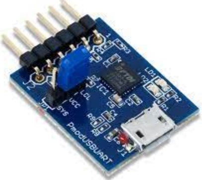
The Digi lent PmodUSBUART is a USB to UART Serial converter module capable of transfer rates upwards of 3 Mbaud.
The PmodUSBUART.

Features include:
- USB to serial UART interface
- Micro USB connector
- Option to power the system board through the FTDI chip
- Small PCB size for flexible designs 1.0“ × 0.8” (2.5 cm × 2.0 cm)
- 6-pin Pmod connector with UART interface
- Follows the Digi lent Pmod Interface Specification Type 4
Functional Description
The PmodUSBUART provides a USB to UART cross-conversion through the FTDI FT232RQ. Users may send data in either direction on the Pmod and receive the converted data in the appropriate format.
Interfacing with the Pmod
The PmodUSBUART communicates with the host board via the UART protocol. Users may either provide data through the USB port or have the on-board FTDI chip automatically translate the USB styled data into the UART protocol. Similarly, data provided through UART is automatically translated by the FTDI chip to the USB interface. Different speeds, parity, and other settings can be configured through a terminal emulator on your computer.
Table 1. Pinout description table.
| Connector J2 – UART Communications | ||
| Pin | Signal | Description |
| 1 | RTS | Ready to Send |
| 2 | RXD | Receive |
| 3 | TXD | Transmit |
| 4 | CTS | Clear to Send |
| 5 | GND | Ground |
| 6 | SYS3V3 | Power Supply (3.3V) |
| Jumper JP1 | ||
| 1 | LCL3V3 | The attached system board is powered independently fromthe PmodUSBUART |
| 1 | SYS3V3 | The attached system board is powered through the on-board FTDI chip |
Any external power applied to the Pmod must be within 2.5V and 5.5V; however, it is recommended that the Pmod is operated at 3.3V.
SYS3V3 Select (Header JP1)
The board attached to the PmodUSBUART can have its 3.3V rail powered by the header JP1. If jumper JP1 is set to SYS, then the SYS3V3 pin is powered by the VCC outputted by the FTDI chip. If the board attached to the PmodUSBUART is powered on its own, the jumper should be set to LCL.
LEDs
There are two LED indicators on the PmodUSBUART. LD1 indicates a data transfer from the micro-USB connector (J1) to the UART connector (J2). LD2 indicates a data transfer from the UART connector (J2) to the micro-USB connector (J1).
Physical Dimensions
The pins on the pin header are spaced 100 mil apart. The PCB is 1.0 inches long on the sides parallel to the pins on the pin header and 0.8 inches long on the sides perpendicular to the pin header.
Copyright Digilent, Inc. All rights reserved.
Other product and company names mentioned may be trademarks of their respective owners.
Downloaded from Arrow.com.
1300 Henley Court
Pullman, WA 99163
509.334.6306
www.digilentinc.com

Documents / Resources
 |
DIGILENT PmodUSBUART USB to UART Serial Converter Module [pdf] Owner's Manual PmodUSBUART USB to UART Serial Converter Module, PmodUSBUART, USB to UART Serial Converter Module, Serial Converter Module, Converter Module, Module |