Danfoss PR OCTO Monitoring Unit Type
Specifications
- Product Name: Monitoring unit Type PR-OCTO
- Function: IoT Enabler for remote control and tracking of refrigeration equipment
- Designed for: Cooling applications like bottle coolers, ice cream cabinets, and other refrigeration equipment
- Connectivity: Access to AlsenseTM Cloud solutions from Danfoss
- After-sales Maintenance: Continuous maintenance with remote updates (FOTA) or on-site updates via mobile app
Product Usage Instructions
- Introduction:
The PR-OCTO device is an IoT Enabler designed for cooling applications such as bottle coolers and ice cream cabinets. It provides connectivity to the AlsenseTM Cloud solutions from Danfoss. - Layout:
The device allows access to AlsenseTM for monitoring and control. It can trigger alarms if the refrigeration system’s position differs from the transmitted data. Authorized personnel can view active alarms on AlsenseTM and decide on actions. - Compatibility:
The PR-OCTO device is compatible with electronic thermostats listed in Table 2. It requires connections for power supply and communication with the electronic thermostat. - Connections and Wires:
The PR-OCTO device needs two connections: one for the power supply and the other for the electronic thermostat. Ensure the power supply is shared with the thermostat to avoid communication failures.
Introduction
- The PR-OCTO device is an IoT Enabler specifically designed for cooling applications like bottle coolers, ice cream cabinets and other refrigeration type of equipment. This Enabler allows connectivity and access to the Alsense™ Cloud solutions from Danfoss.
- Electronic thermostats, in general, by monitoring the temperatures and states related to the equipment, control the compressor and fan relays and generate warnings and alarms. By means of
a wired connection, PR-OCTO can obtain from the thermostats diagnostic and alarm data relating
to the equipment, or create new ones. Thanks to the presence of a modem and an M2M SIM on board, PR-OCTO communicates with the Alsense™ monitoring platform through the mobile network, transmitting the collected data. PR- OCTO also scans the mobile network and nearby WiFi HotSpots to determine its position and transmit it to Alsense™. - If in Alsense™ the refrigeration system is located in a position other than that transmitted by PR-OCTO, an alarm is notified on the monitoring platform. Authorized personnel can access Alsense™ to view active alarms and decide if PR-OCTO has to lock the operation of the refrigeration system.
- Danfoss guarantees a continuous after-sales maintenance of the PR-OCTO devices as they can be updated remotely (FOTA) or on site via the mobile app.
Layout
Figure 1 and Figure 2 illustrate the layout of the PR-OCTO device.
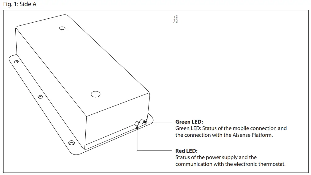
See Table 1 for details on the operation.
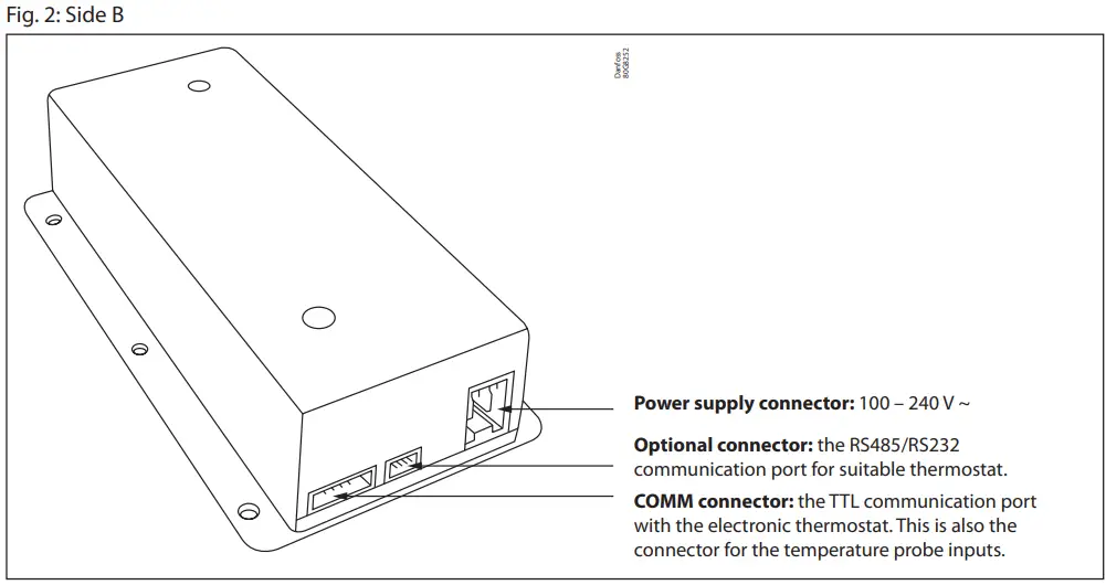
Table 1: LED operation details
| RED LED OFF | The device is not correctly powered. |
| RED LED blinking | The device is powered and the communication with the electronic thermostat is not established yet. |
| RED LED ON | The device is powered and the communication with the electronic thermostat is correctly established. |
| RED LED fast blinking | The device is powered while the communication with the electronic thermostat has been interrupted. |
| GREEN LED OFF | The modem is not running |
| GREEN LED fast blinking | The modem is not registered to the network |
| GREEN LED blinking | The modem is registered to the network |
Compatibility
- The PR-OCTO device gives the possibility to block the compressor and to collect the diagnostic information only in conjunction with an electronic thermostat.
- The current version of the PR-OCTO includes the compatibility with the thermostats listed in Table 2.
Table 2: Compatible electronic thermostats
| Manufacturer | Models |
| Danfoss | ERC111, ERC112, EETa |
| Eliwell | EWPLUS400, EWPLUS961, EWPLUS974, EWPLUS974 Smart, EWPLUS978 |
| Carel | PJP4C0HG00 (PYUG3R05R3, PYKM1Z051P), PZPU family (es. PZPUCOMB03K, PZPUCOMB06K), PYHB1R055S (PYFZ1Z056M), PZHBC0H00V, PYHB1R057F (PYHB1R05E9), PJP7C0HG00 |
Connections and wires

- The PR-OCTO requires two connections, one for the power supply, the other with the electronic thermostat.
- The power supply must be shared with the electronic thermostat: the PR-OCTO must be powered on only when the thermostat is also powered on. If the PR-OCTO is powered on when the thermostat is off, a “Controller communication failure” alarm is raised after 60 minutes.
- Note: Neither the cables nor the connectors are included in the PR-OCTO package.
- For the POWER SUPPLY connector of the PR-OCTO, either two standard fast-on connectors or one connector with screw terminal can be used. In Fig 4, illustrates the Lumberg 3611 02 K1, an easy plug connector with lift clamp and protection against misplacing and fast assembling. Neither the easy plug connector nor the standard fast-on connectors are included in the PR-OCTO package.
- Note: If the power supply cable is not double insulated, it must be physically separated from the COMM cable.
Fig. 4: Two possible PR-OCTO terminations for the power supply cable.
The one on the right is the Lumberg 3611 02 K1.

- Concerning the COMM Cable (the communication cable between the PR-OCTO and the electronic thermostat) a specified cable must be used depending on the specified thermostat.
- The COMM Cable could be either assembled by the cooler manufacturer or could be purchased from Danfoss (see COMM table for details).
| Controller | Length | Code no. |
| ERC11x | 0.6 m | 080G3396 |
| ERC11x | 2 m | 080G3388 |
| ERC11x | 4 m | 080G3389 |
| EETa | 2 m | 080N0330 |
| EETa | 4 m | 080N0331 |
For other options on cabling and connection to different controllers, please contact Danfoss.
Choosing the position in the cooler
The most important requirement for the PR-OCTO installation is to find the location inside the cooler where the mobile network signal is stronger and the device protected. The diagram below suggests the recommended positions for coolers:

- On standard visi coolers the best area is inside the canopy, since the canopy usually does not have metal plates that could decrease the mobile network signal.
- On lean cooler, since the lack of the canopy and the presence of metallic plates all around the cooler, the PR-OCTO can only be installed outside the cooler, in the back area, next to the top.
- Note: In case of installation on the back side of the cooler, the PR-OCTO has to be protected with an additional box to protect people from electric shock.
Mobile application (recommended)
- Danfoss has developed a mobile application for Android and IoS that can be used also for check the best position where to install the PR-OCTO in the cooler. This is the suggested way to check the best position to install the PR-OCTO into the cooler.
- You can find more details at: User Guide for ProsaLink mobile app
PC application
Danfoss has developed a specific PC software to help discovering the right position of the PR-OCTO in the cooler. To exploit such software, follow these steps:
- Step 1: Download the VBCTKSignalTester application from this URL: http://area.riservata.it/vbctksignaltester-1.0.0-setup-x86_32.exe
- Step 2: Install the VBCTKSignalTester application in a Windows PC.
- Step 3: Connect the ‘Test Cable’ (see Fig. 5) to the PC and to the PR-OCTO.
- Step 4: Power on the PR-OCTO (see Section 4 for the power supply cable).
- Step 5: Run VBCTKSignalTester and select the appropriate Serial COM port to which the ‘Test Cable’ is connected, as shown in Fig. 6a.
- Step 6: If the program shows “No Connection” as in Fig. 6b, try to change the COM port listed in the combo or check the cable connection.
- Step 7: When the system is finally connected to the device, it starts to display the Antenna Signal Level of the PR-OCTO’s internal antenna. Such level could be low (like in Fig. 6e), medium intensity (like in Fig. 6f) or almost the best signal level (like in Fig. 6d).
- Step 8: Try to change the position of the PR-OCTO in the cooler in order to discover the highest possible Antenna Signal Level.
- Step 9: Power off the PR-OCTO and disconnect the PC ‘test cable’.
Fig. 5: PC Test Cable for monitoring the PR-OCTO GPRS transmission signal level.


Once discovered the best position with respect to the Antenna Signal Level, it is possible to decide if it is the case to protect the Side B (the one with the connectors) of the PR-OCTO. To this aim, it can be adopted the same approach that the cooler manufacturer uses to protect the connector side of the electronic thermostat, hence a piece of plastic with an appropriate shape can be used. If a piece of plastic is not available, a metallic plate can be used but the covered area of the PR-OCTO has to be as small as possible (the limit should be 5 cm from the front of the PR-OCTO, as illustrated in Fig. 7).

Installation in the coolers
During the industrial production of the coolers, there should be a phase in which the electronic thermostat is installed. In the same phase, also the PR-OCTO device has to be installed. The following pre-conditions have to be satisfied:
- Pre-condition 1: The installation position has to be determined during the analysis performed as described in Section 5.
- Pre-condition 2: One COMM CABLE for each cooler has been correctly assembled for the corresponding thermostat model with the appropriate length with respect to the position of both the PR-OCTO and the electronic thermostat.
- Pre-condition 3: A power supply cable has been prepared using one of the connectors illustrated in Fig. 4.
- Pre-condition 4: If a metal protection is provided, this must not cover the antenna of the device (see Fig. 7).
- Pre-condition 5: the controller has to be programmed in order to properly manage all the sensors. Thus, for example, if a door sensor is installed, even if it is not needed for the cooler management (i.e. no need to switch off the fan), the controller must be programmed in order to properly detect and manage the door sensor itself. For any clarification, ask your local Danfoss agent.
For the installation, the following steps have to be performed:
- Step 1: While the cooler is off, put the PR-OCTO unplugged inside the cooler in the appropriate position.
- Step 2: Connect the COMM cable to the thermostat and to the PR-OCTO.
- Step 3: Connect the power supply cable to the PR-OCTO while such cable is not powered, as illustrated in Fig. 3.
- Step 4: Install the protection, if any.
- Step 5: Power on the cooler (and consequently the PR-OCTO). The red led of the PR-OCTO starts blinking. Wait until the red led stops blinking. If it results always on, then the device is powered and the communication with the electronic thermostat is correctly established.
- Step 6: Wait until the green led remains always on.
- Step 7: In case of success in STEP 6, and only in such case, the cooler code and the PR-OCTO code have to be associated. This association is described in section 7.
Note: In case STEP 7 is not properly executed, the future owner of the cooler will not recognize the cooler through the Alsense infrastructure.

Alsense association
This section is to highlight the procedure to associate the cooler code to the PR-OCTO code of the STEP 7 listed in Section 6.
The association between the equipment and the PR-OCTO can be done:
or other modalities previously agreed with Danfoss (contact via e-mail: support.prosa@danfoss.com).
The association must be done before to ship the equipment to the final customer. Any shipment to the final customer must be notified with an e-mail containing the equipment codes and the customer’s warehouse address to support.prosa@danfoss.com.
Technical specification
The technical specification can be found on the following datasheets:
Dimensions


Warnings
- The installation of the PR-OCTO has to be performed only and exclusively by qualified and skilled technicians.
- The installation of the PR-OCTO should be performed while the cooler is switched-off.
- Inside the device there is a GPRS antenna. For this reason, while the PR-OCTO is working it must be at the minimum distance of 9.5 cm (4”) from the people. The installation must be done to ensure this distance.
- The PR-OCTO has to be installed in a protected position. The PR-OCTO has to be embedded in the cooler and not accessible. In case of installation on the back side of the cooler, the PR-OCTO has to be protected with an additional box to protect people from electric shock.
- If the power supply cable of the PR-OCTO is not double insulated, it has to be physically separated from the COMM cable (the communication cable with the thermostat).
- The PR-OCTO input power supply is protected by over-currents by the F002 device, with this characteristics: delayed fuse 250 V 400 mA.
- Any document related to the conformity declaration of the PR-OCTO can be downloaded from www.danfoss.com.
- This equipment is not suitable for use in locations where children are likely to be present.
Danfoss A/S
Climate Solutions • danfoss.com • +45 7488 2222
Any information, including, but not limited to information on selection of product, its application or use, product design, weight, dimensions, capacity or any other technical data in product manuals cataloques descriptions, advertisements, etc. and whether made available in writing, orally, electronically, online or via download, shall be considered informative, and is only binding if and to the extent, explicit reference is made in a quotation or order confirmation. Danfoss cannot accept any responsibility for possible errors in cataloques, brochures, videos and other materia Janfoss reserves the right to alter its products without notice. This also applies to products ordered but not delivered provided that such alterations can be made without changes to form, fit or function of the product.
All trademarks in this material are property of Danfoss A/S or Danfoss group companies. Danfoss and the Danfoss logo are trademarks of Danfoss A/S. All rights reserved.
FAQ
What does the red LED blinking indicate?
Red LED blinking indicates that the device is powered, but communication with the electronic thermostat is not established yet.
How can I update the PR-OCTO device?
You can update the PR-OCTO device remotely using FOTA or on-site via the mobile app provided by Danfoss.
Can the PR-OCTO device work independently without an electronic thermostat?
No, the PR-OCTO device requires an electronic thermostat to function properly, including features like blocking the compressor and collecting diagnostic information.
Documents / Resources
 |
Danfoss PR OCTO Monitoring Unit Type [pdf] User Guide BC391624209008en-000302, PR OCTO Monitoring Unit Type, PR OCTO, Monitoring Unit Type, Unit Type |