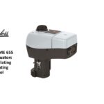
Danfoss AME 130 Series Actuators for Modulating Control

Specifications
- Model: AME 130(H), AME 140(H)
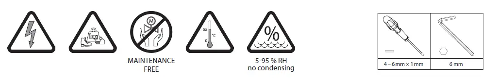
- Maintenance: Maintenance Free
- Operating Range: 5-95% RH (no condensing)
- Actuator Dimensions: 6 mm
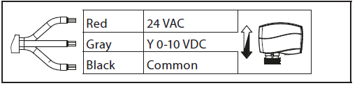
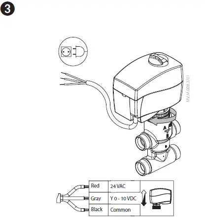
- Power Requirements: Red 24 VAC, Gray Y 0-10 VDC, Black Common
Safety Instructions
Safety Note
- To avoid injury of persons and damages to the device, it is absolutely necessary to read and observe these instructions carefully.
- Necessary assembly, start-up, and maintenance work must be performed by qualified and authorized personnel only.
- Please comply with the instructions of the system manufacturer or system operator.
- Do not remove the cover before the power supply is fully switched off.
Disposal instruction
- This product should be dismantled and its components sorted, if possible, in various groups before recycling or disposal.
- Always follow the local disposal regulations.
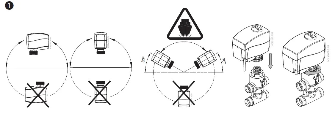
Mounting ➊
- In case of ship applications (on water) actuator should be mounted with the valve stem in either 30° above horizontal position or pointing upwards.
- In case of building applications actuator should be mounted with the valve stem in either horizontal position or pointing upwards. The actuator is fixed to the valve body by means of a ribbed nut which requires no tools for mounting. The ribbed nut should be tightened by hand.
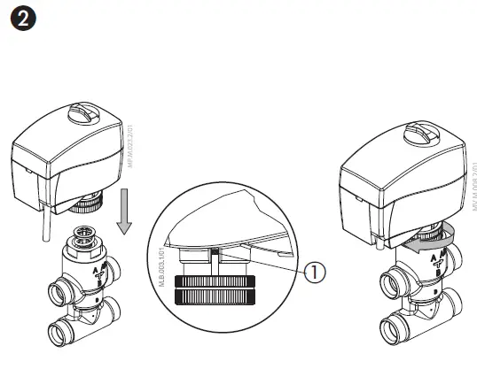
Installation ❷
- Check the valve neck. The actuator should be in steam up position (factory setting). Ensure that the actuator is mounted securely on the valve body
- Wire the actuator according to the wiring diagram
- The direction of stem movement can be observed on the position indicator ①
Wiring ❸
- Do not touch anything on the PCB! Switch off the power line before wiring the actuator! Lethal voltage!
- Wire the actuator according to the wiring diagram.
DIP switch settings ➍
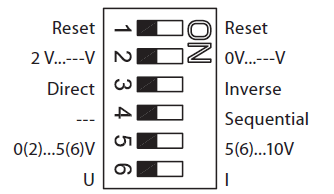
Factory settings:
ALL switches are on OFF position!
NOTE: All combinations of DIP switches are allowed. All functions that are selected are added consecutively.
SW1: Reset ②
After the actuator has been connected to power supply, the actuator will start the self-adjustment procedure. The indicator LED ① flashes until self adjustment is finished. The duration depends on the spindle travel and will normally last a few minutes. The stroke length of the valve is stored in the memory after self adjustment has been completed. To restart self adjustment, change the position of the RESET switch (switch No.1). If the supply voltage is switched off or falls below 80 % in more than 0.1 s, the current valve position will be stored in the memory and all data remain saved in the memory also after a power supply cut-out.
SW2: 2-10 V/0-10 V ③
Factory setting is: 2-10 V.
SW3: Direct/Inverse ④
The actuator can be set for the spindle to travel downwards on the rising control signal (DIRECT), OR for the spindle to travel upwards on the rising control signal (INVERSE)
Factory setting is:VI.KU.M6.9ODIRECT
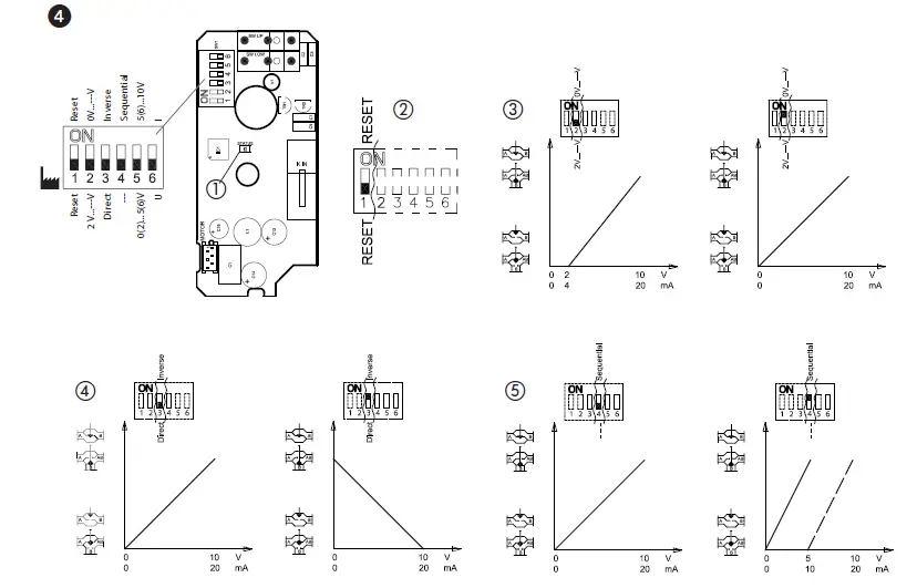
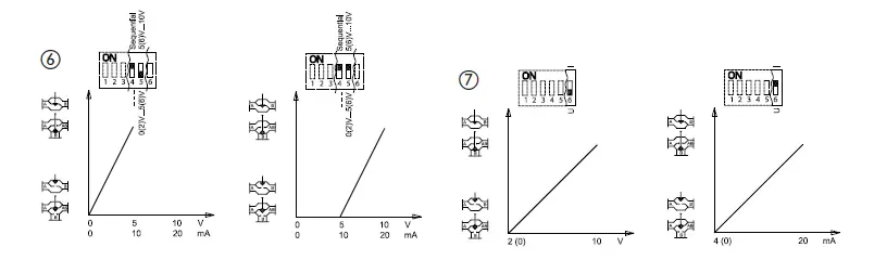
- SW4: —/Sequential ⑤
NOTE: This combination works in combination with switch No.5: 0(2)-5(6) V/5(6)-10 V.
SW5: 0(2)-5(6) V/5(6)-10 V ⑥ - NOTE: This function is available if switch
No.4: —/Sequential is set. - SW6: U/I ⑦
Factory setting: voltage control signal (2-10 V).
Manual override (for service purposes only)
Do not manually operate the drive under power!
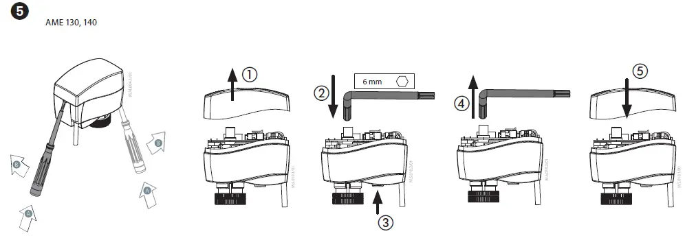
AME 130, AME 140 ➎
- Remove the cover
- Insert the Allen key 6 into the spindle
- Press and hold the button (on the bottom side of the actuator) during manual override
- Pull out the tool
- Replace cover
Remark: A ‘click’ sound after energising the actuator means that the gear wheel has jumped into normal position.
AME 130H, AME 140H ❻
Press and hold the button ① (on the bottom side of the actuator) during manual override.
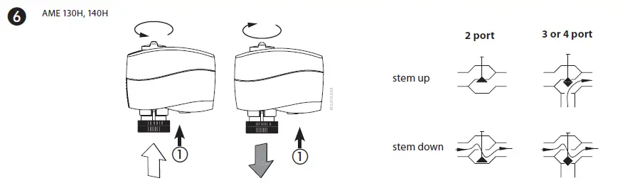
Remark: A ‘click’ sound after energising the actuator means that the gear wheel has jumped into normal position.
Function test
The light emitting diode (LED) ❹① indicates whether the actuator is in operation or not, the operating status, and failures, if any.
- No light
- no operation or no power supply
- Constant light
- normal operation
- Flashing light (1 Hz)
- self-adjusting mode
- Flashing light (~ 3 Hz):
- power supply too low
- initial self-adjusting time to short due too short valve’s stroke must last more than 12 sec.
Dimensions ❼
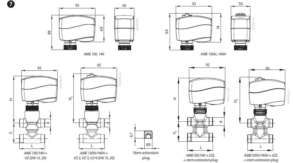
| Valve type | d | L | H | H1 | h |
| mm | |||||
| VZ 2 / DN 15 | G ½” | 65 | 119 | 125 | 26.5 |
| VZ 2 / DN 20 | G ¾” | 77 | |||
| VZ 3 / DN 15 | G ½” | 65 | 35 | ||
| VZ 3 / DN 20 | G ¾” | 77 | |||
| VZ 4 / DN 15 | G ½” | 65 | 65 | ||
| VZ 4 / DN 20 | G ¾” | 77 | |||
| Valve type | d | L | H | H1 | h1 |
| mm | |||||
| VZL 2 DN 15 | G ½” | 65 | 111 | 117 | 29.5 |
| VZL 2 DN 20* | G ¾” | 77 | 117 | 123 | 34.0 |
| VZL 3 DN 15 | G ½” | 65 | 111 | 117 | 35.0 |
| VZL 3 DN 20 | G ¾” | 77 | 117 | 123 | 35.0 |
| VZL 4 DN 15 | G ½” | 65 | 111 | 117 | 51.0 |
| VZL 4 DN 20* | G ¾” | 77 | 117 | 123 | 65.0 |
* conex valves DN 20 – G 1 ¹/₈” 14 TPI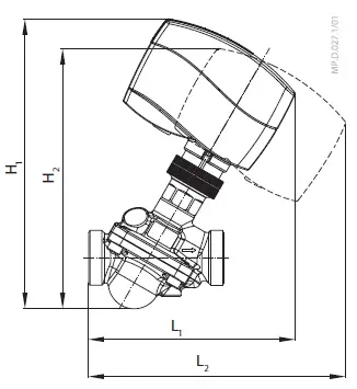
| DN | 15 | 20 | 25 | 32 | |
| L1 | mm | 118 | 125 | 141 | 160 |
| L2 | 148 | 156 | 174 | 194 | |
| H1 | 168 | 178 | 196 | 216 | |
| H2 | 152 | 162 | 180 | 200 | |
| Part Name | Hazardous Substances Table | |||||
| Lead (Pb) | Mercury (Hg) | Cadmium (Cd) | Hexavalent Chromium (Cr(VI)) | Polybrominated biphenyls (PBB) | Polybrominated diphenyl ethers (PBDE) | |
| Connecting nut | X | O | O | O | O | O |
| O: Indicates that this hazardous substance contained in all of the homogeneous material for this part is below the limit requirement in GB/T 26572; O: | ||||||
| X: Indicates that this hazardous substance contained in at least one of the homogeneous material for this part is above the limit requirement in GB/T 26572; X: | ||||||
Danfoss can accept no responsibility for possible errors in catalogues, brochures and other printed material. Danfoss reserves the right to alter its products without notice. This also applies to products already on order provided that such alterations can be made without sub sequential changes being necessary early agreed.
All trademarks in this material are property of the respective companies. Danfoss and the Danfoss logotype are trademarks of Danfoss A/S. All rights reserved.
Frequently Asked Questions
- Q: Can I dismantle the product for recycling or disposal?
- A: Yes, the product should be dismantled and components sorted for recycling. Always follow local disposal regulations.
- Q: What safety precautions should be taken during installation?
- A: To avoid injury or damage, ensure that assembly, start-up, and maintenance are done by qualified personnel. Do not remove the cover before switching off the power supply.
Documents / Resources
 |
Danfoss AME 130 Series Actuators for Modulating Control [pdf] User Guide AME 130, AME 140, ME 130H, AME 140H, AME 130 Series Actuators for Modulating Control, AME 130 Series, Actuators for Modulating Control, Modulating Control |