ARGOX I4/iX4 Series GPIO Interface Control
Product Information
Specifications
The GPIO interface is designed for Argox industrial printers and external peripheral devices.
- Connector: D-Sub 15-pin female connector
- Input Pins: Standard TTL levels
- Output Pins: Standard TTL levels, pulled up 1K ohm internally by 5V, maximum sink current 30mA
- Power Supplies: 5V (max supply current 500mA), 24V (max supply current 1A)
Connector Pin Specification
- All input pins are defined as standard TTL levels.
- All output pins are defined as standard TTL levels and internally pulled up by 5V with a maximum sink current of 30mA.
- The ground (pin1 and pin8) of the GPIO board and the signal ground of the external device need to connect directly.
- The connecting cable length between the GPIO interface and the external device should be less than 15 feet.
Input/Output Signal Description
There are four input pins for the application:
- Start Print (Pin 3):
- This signal initiates the print job (active low).
- When the print job is finished, the End Print pin sends a low pulse (20ms).
- Data Ready pin goes active low when data is ready for printing.
Product Usage Instructions
- Installation:
Follow the installation guide to connect the GPIO card to the industrial printer. - Operation:
Program or customize the GPIO interface to control printer functions. - Connector Pin Connections:
Ensure proper connection of pins based on the provided pin definitions. - Cable Length:
Keep the cable length between the GPIO interface and the external device under 15 feet to prevent noise and errors.
FAQ
- Q: What is the maximum sink current for output pins?
A: The maximum sink current for output pins is 30mA. - Q: How should I handle the Start Print signal?
A: The Start Print signal initiates the print job and is active low. Ensure to follow the timing chart for proper operation.

Specifications
- The GPIO interface is designed for Argox industrial printers and external peripheral devices.

- The GPIO interface works in exceptional control by changing input signal levels; it’s programmable or customized, and output signals show the printer status or functional indicator.

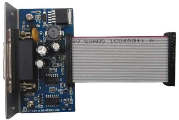
- The GPIO interface is as shown in Figure 2 and Figure 3; it uses a D-Sub 15-pin female connector.

- Connector pin definitions are as follows:
| Pin No. | Type | Default Function |
Description |
| 1 | P | GND | Power return path of +5V |
| 2 | P | +5V | Power plus path of +5V |
| 3 | I | Start Print | Start printing. Trigger this signal (high to low) to enable the printer to print one received format label. |
| 4 | I | Feed | Feed. Trigger this signal (from high to low) to feed one label. It’s the same as the “FEED” key on the panel. |
| 5 | I | Pause | Pause. When this signal is triggered (high to low), the printer pauses or stops the print job until the next pause signal is triggered. |
| 6 | I | Reprint | Reprint. The printer reprints the last label when this signal is triggered (high to low). |
| 7 | P | 24V | Power plus path of +24V |
| 8 | P | GND | Power return path of +24V |
| 9 | NC | Not Connect | |
| 10 | O | Serv_Req | Service required. When a printer error occurs, this output signal will change from high to low (active low). |
| 11 | O | End Print | End of print. Output a low pulse signal in 20ms at the end of printing. |
| 12 | O | Media Out | Media out. When the printer runs out of paper or has a paper jam error, this output signal will change from high to low (active low). |
| 13 | O | Ribbon Out | Ribbon out. When the ribbon runs out, this output signal will change from high to low (active low). |
| 14 | O | Data Ready | The data is ready. This output signal will change from high to low (active low) when printing data is received and waiting to trigger printing. |
| 15 | O | OPT Fault | Output fault. When a printer error occurs, this output signal will change from high to low (active low). |
Type: P for Power; I for Input; O for Output Table 1
Connector pin specification
- All of the input pins in the table are defined as standard TTL levels.
- All of the output pins in the table are defined as standard TTL levels; they are pulled up 1K ohm internally by 5V, and the maximum sink current is 30mA.
- There are two power supplies for external devices; the maximum supply current of 5V is 500mA, and 24V is 1A.
- Because all of the signals were not isolated, the ground (pin1 and pin8) of the GPIO board and the signal ground of the external device need to connect directly; it should avoid different GND pins connecting the GPIO board and making this board fail.
- Suggest that the length of the connecting cable between the GPIO interface and the external device should be less than 15 feet to avoid noise and errors.
Input/Output Signal Description
There are four input pins for the application.
- Pin 3
Start Print:- This signal makes the printer start to do the print job; it is active low.
- When the print job is finished, the output pin of End Print will send a low pulse (20ms), and the external device should turn off the Start Print signal.
- When data to be printed is received, the output pin of Data Ready will active low.
- The timing chart is shown in Figure 4.

- Pin 4
Feed:- The signal is to let the printer feed the media; the internal label length sets the distance.
- During feed processing, the output pin of Data Ready will be active and disabled till the end of the feed.
- The timing chart is shown in Figure 5.

- Pin 5
Pause:- The signal causes the printer to pause action; it is a toggle (on/off) mode when the printer needs to be temporarily stopped.
- During pause processing, the output pin of OPT Fault will be active low and disabled until the pause signal is active again.
- The timing chart is shown in Figure 6.

- Pin 6
Reprint:- This signal makes the printer print the last label again; it is active low.
- When the print job is finished, the output pin of End Print will send a pulse (20ms), and the external device should turn off the Re-Print signal.
- The output pin of Data Ready will be active and disabled till the end of printing.
- The timing chart is shown in Figure 7.

There are six output pins for the printer’s application; the timing chart is shown in Figure 8.
- Pin 10
Serv_Req:- The signal will be active when a printer error occurs.
- Pin 11
End Print:- It indicates the printer’s status and is active when the printing page is complete.
- The action timing is about 20ms.
- Pin 12
Media out:- It indicates the media status and is active when media (paper) out occurs.
- This signal persists until the error condition is removed.
- Pin 13
Ribbon out:- It indicates the ribbon status and is active when ribbon out occurs.
- This signal persists until the error condition is removed.
- Pin 14
Data Ready:- It indicates the printer has received print data.
- In this state, the printer could accept the input Start Print signal to start the print job.
- Pin 15
OPT Fault:- It indicates all the printer’s error status. If it is active, please perform the troubleshooting procedure.
- This signal persists until the error condition is removed.

Documents / Resources
 |
ARGOX I4/iX4 Series GPIO Interface Control [pdf] Instruction Manual I4, iX4 Series, I4 iX4 Series GPIO Interface Control, I4 iX4 Series, GPIO Interface Control, Interface Control, Control |