![]() ESP32 Basic Starter
ESP32 Basic Starter
Kit
Packing List

ESP32 Introduction
New to ESP32? Start here! The ESP32 is a series of low-cost and low-power System on a Chip (SoC) microcontrollers developed by Espressif that include Wi-Fi and Bluetooth wireless capabilities and dual-core processor. If you’re familiar with the ESP8266, the ESP32 is its successor, loaded with lots of new features. ESP32 Specifications
If you want to get a bit more technical and specific, you can take a look at the following detailed specifications of the ESP32 (source: http://esp32.net/)—for more details, check the datasheet):
- Wireless connectivity WiFi: 150.0 Mbps data rate with HT40
- Bluetooth: BLE (Bluetooth Low Energy) and Bluetooth Classic
- Processor: Tensilica Xtensa Dual-Core 32-bit LX6 microprocessor, running at 160 or 240 MHz
- Memory:
- ROM: 448 KB (for booting and core functions)
- SRAM: 520 KB (for data and instructions)
- RTC fas SRAM: 8 KB (for data storage and main CPU during RTC Boot from the deep-sleep mode)
- RTC slow SRAM: 8KB (for co-processor accessing during deep-sleep mode) eFuse: 1 Kbit (of which 256 bits are used for the system (MAC address and chip configuration) and the remaining 768 bits are reserved for customer applications, including Flash-Encryption and Chip-ID)
Embedded flash: flash connected internally via IO16, IO17, SD_CMD, SD_CLK, SD_DATA_0 and SD_DATA_1 on ESP32-D2WD and ESP32-PICO-D4.
- 0 MiB (ESP32-D0WDQ6, ESP32-D0WD, and ESP32-S0WD chips)
- 2 MiB (ESP32-D2WD chip)
- 4 MiB (ESP32-PICO-D4 SiP module)
Low Power: ensures that you can still use ADC conversions, for example, during deep sleep.
Peripheral Input/Output:
- peripheral interface with DMA that includes capacitive touch
- ADCs (Analog-to-Digital Converter)
- DACs (Digital-to-Analog Converter)
- I²C (Inter-Integrated Circuit)
- UART (Universal Asynchronous Receiver/Transmitter)
- SPI (Serial Peripheral Interface)
- I²S (Integrated Interchip Sound)
- RMII (Reduced Media-Independent Interface)
- PWM (Pulse-Width Modulation)
Security: hardware accelerators for AES and SSL/TLS
ESP32 Development Boards
ESP32 refers to the bare ESP32 chip. However, the “ESP32” term is also used to refer to ESP32 development boards. Using ESP32 bare chips is not easy or practical, especially when learning, testing, and prototyping. Most of the time, you’ll want to use an ESP32 development board.
We’ll be using the ESP32 DEVKIT V1 board as a reference.The picture below shows the ESP32 DEVKIT V1 board, version with 30 GPIO pins.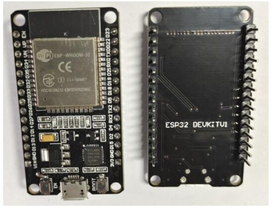 Specifications – ESP32 DEVKIT V1
The following table shows a summary of the ESP32 DEVKIT V1 DOIT board features and specifications:
| Number of cores | 2 (dual core) |
| Wi-Fi | 2.4 GHz up to 150 Mbits/s |
| Bluetooth | BLE (Bluetooth Low Energy) and legacy Bluetooth |
| Architecture | 32 bits |
| Clock frequency | Up to 240 MHz |
| RAM | 512 KB |
| Pins | 30(depending on the model) |
| Peripherals | Capacitive touch, ADC (analog to digital converter), DAC (digital to analog converter), 12C (Inter-Integrated Circuit), UART (universal asynchronous receiver/transmitter), CAN 2.0 (Controller Area Netwokr), SPI (Serial Peripheral Interface), 12S (Integrated Inter-IC Sound), RMII (Reduced Media-Independent Interface), PWM (pulse width modulation), and more. |
| Built-in buttons | RESET and BOOT buttons |
| Built-in LEDs | built-in blue LED connected to GPIO2; built-in red LED that shows the board is being powered |
| USB to UART bridge |
CP2102 |
 It comes with a microUSB interface that you can use to connect the board to your computer to upload code or apply power.
It uses the CP2102 chip (USB to UART) to communicate with your computer via a COM port using a serial interface. Another popular chip is the CH340. Check what’s the USB to UART chip converter on your board because you’ll need to install the required drivers so that your computer can communicate with the board (more information about this later in this guide).
This board also comes with a RESET button (may be labeled EN) to restart the board and a BOOT button to put the board in flashing mode (available to receive code). Note that some boards may not have a BOOT button.
It also comes with a built-in blue LED that is internally connected to GPIO 2. This LED is useful for debugging to give some sort of visual physical output. There’s also a red LED that lights up when you provide power to the board. ESP32 Pinout
The ESP32 peripherals include:
- 18 Analog-to-Digital Converter (ADC) channels
- 3 SPI interfaces
- 3 UART interfaces
- 2 I2C interfaces
- 16 PWM output channels
- 2 Digital-to-Analog Converters (DAC)
- 2 I2S interfaces
- 10 Capacitive sensing GPIOs
The ADC (analog to digital converter) and DAC (digital to analog converter) features are assigned to specific static pins. However, you can decide which pins are UART, I2C, SPI, PWM, etc – you just need to assign them in the code. This is possible due to the ESP32 chip’s multiplexing feature.
Although you can define the pins properties on the software, there are pins assigned by default as shown in the following figure Additionally, there are pins with specific features that make them suitable or not for a particular project. The following table shows what pins are best to use as inputs, outputs and which ones you need to be cautious.
The pins highlighted in green are OK to use. The ones highlighted in yellow are OK to use, but you need to pay attention because they may have an unexpected behavior mainly at boot. The pins highlighted in red are not recommended to use as inputs or outputs.
| GP IO | Input | Output | Notes |
| 0 | pulled up | OK | outputs PWM signal at boot, must be LOW to enter flashing mode |
| 1 | TX pin | OK | debug output at boot |
| 2 | OK | OK | connected to on-board LED, must be left floating or LOW to enter flashing mode |
| 3 | OK | RX pin | HIGH at boot |
| 4 | OK | OK | |
| 5 | OK | OK | outputs PWM signal at boot, strapping pin |
| 12 | OK | OK | boot fails if pulled high, strapping pin |
| 13 | OK | OK | |
| 14 | OK | OK | outputs PWM signal at boot |
| 15 | OK | OK | outputs PWM signal at boot, strapping pin |
| 16 | OK | OK | |
| 17 | OK | OK | |
| 18 | OK | OK | |
| 19 | OK | OK | |
| 21 | OK | OK | |
| 22 | OK | OK | |
| 23 | OK | OK | |
| 25 | OK | OK | |
| 26 | OK | OK | |
| 27 | OK | OK | |
| 32 | OK | OK | |
| 33 | OK | OK | |
| 34 | OK | input only | |
| 35 | OK | input only | |
| 36 | OK | input only | |
| 39 | OK | input only |
Continue reading for a more detail and in-depth analysis of the ESP32 GPIOs and its functions.
Input only pins
GPIOs 34 to 39 are GPIs – input only pins. These pins don’t have internal pull-up or pull-down resistors. They can’t be used as outputs, so use these pins only as inputs:
- GPIO 34
- GPIO 35
- GPIO 36
- GPIO 39
SPI flash integrated on the ESP-WROOM-32
GPIO 6 to GPIO 11 are exposed in some ESP32 development boards. However, these pins are connected to the integrated SPI flash on the ESP-WROOM-32 chip and are not recommended for other uses. So, don’t use these pins in your projects:
- GPIO 6 (SCK/CLK)
- GPIO 7 (SDO/SD0)
- GPIO 8 (SDI/SD1)
- GPIO 9 (SHD/SD2)
- GPIO 10 (SWP/SD3)
- GPIO 11 (CSC/CMD)
Capacitive touch GPIOs
The ESP32 has 10 internal capacitive touch sensors. These can sense variations in anything that holds an electrical charge, like the human skin. So they can detect variations induced when touching the GPIOs with a finger. These pins can be easily integrated into capacitive pads and replace mechanical buttons. The capacitive touch pins can also be used to wake up the ESP32 from deep sleep. Those internal touch sensors are connected to these GPIOs:
- T0 (GPIO 4)
- T1 (GPIO 0)
- T2 (GPIO 2)
- T3 (GPIO 15)
- T4 (GPIO 13)
- T5 (GPIO 12)
- T6 (GPIO 14)
- T7 (GPIO 27)
- T8 (GPIO 33)
- T9 (GPIO 32)
Analog to Digital Converter (ADC)
The ESP32 has 18 x 12 bits ADC input channels (while the ESP8266 only has 1x 10 bits ADC). These are the GPIOs that can be used as ADC and respective channels:
- ADC1_CH0 (GPIO 36)
- ADC1_CH1 (GPIO 37)
- ADC1_CH2 (GPIO 38)
- ADC1_CH3 (GPIO 39)
- ADC1_CH4 (GPIO 32)
- ADC1_CH5 (GPIO 33)
- ADC1_CH6 (GPIO 34)
- ADC1_CH7 (GPIO 35)
- ADC2_CH0 (GPIO 4)
- ADC2_CH1 (GPIO 0)
- ADC2_CH2 (GPIO 2)
- ADC2_CH3 (GPIO 15)
- ADC2_CH4 (GPIO 13)
- ADC2_CH5 (GPIO 12)
- ADC2_CH6 (GPIO 14)
- ADC2_CH7 (GPIO 27)
- ADC2_CH8 (GPIO 25)
- ADC2_CH9 (GPIO 26)
Note: ADC2 pins cannot be used when Wi-Fi is used. So, if you’re using Wi-Fi and you’re having trouble getting the value from an ADC2 GPIO, you may consider using an ADC1 GPIO instead. That should solve your problem.
The ADC input channels have a 12-bit resolution. This means that you can get analog readings ranging from 0 to 4095, in which 0 corresponds to 0V and 4095 to 3.3V. You can also set the resolution of your channels on the code and the ADC range.
The ESP32 ADC pins don’t have a linear behavior. You’ll probably won’t be able to distinguish between 0 and 0.1V, or between 3.2 and 3.3V. You need to keep that in mind when using the ADC pins. You’ll get a behavior similar to the one shown in the following figure. Digital to Analog Converter (DAC)
There are 2 x 8 bits DAC channels on the ESP32 to convert digital signals into analog voltage signal outputs. These are the DAC channels:
- DAC1 (GPIO25)
- DAC2 (GPIO26)
RTC GPIOs
There is RTC GPIO support on the ESP32. The GPIOs routed to the RTC low-power subsystem can be used when the ESP32 is in deep sleep. These RTC GPIOs can be used to wake up the ESP32 from deep sleep when the Ultra Low
Power (ULP) co-processor is running. The following GPIOs can be used as an external wake up source.
- RTC_GPIO0 (GPIO36)
- RTC_GPIO3 (GPIO39)
- RTC_GPIO4 (GPIO34)
- RTC_GPIO5 (GPIO35)
- RTC_GPIO6 (GPIO25)
- RTC_GPIO7 (GPIO26)
- RTC_GPIO8 (GPIO33)
- RTC_GPIO9 (GPIO32)
- RTC_GPIO10 (GPIO4)
- RTC_GPIO11 (GPIO0)
- RTC_GPIO12 (GPIO2)
- RTC_GPIO13 (GPIO15)
- RTC_GPIO14 (GPIO13)
- RTC_GPIO15 (GPIO12)
- RTC_GPIO16 (GPIO14)
- RTC_GPIO17 (GPIO27)
PWM
The ESP32 LED PWM controller has 16 independent channels that can be configured to generate PWM signals with different properties. All pins that can act as outputs can be used as PWM pins (GPIOs 34 to 39 can’t generate PWM).
To set a PWM signal, you need to define these parameters in the code:
- Signal’s frequency;
- Duty cycle;
- PWM channel;
- GPIO where you want to output the signal.
I2C
The ESP32 has two I2C channels and any pin can be set as SDA or SCL. When using the ESP32 with the Arduino IDE, the default I2C pins are:
- GPIO 21 (SDA)
- GPIO 22 (SCL)
If you want to use other pins when using the wire library, you just need to call:
Wire.begin(SDA, SCL);
SPI
By default, the pin mapping for SPI is:
| SPI | MOSI | MISO | CLK | CS |
| VSPI | GPIO 23 | GPIO 19 | GPIO 18 | GPIO 5 |
| HSPI | GPIO 13 | GPIO 12 | GPIO 14 | GPIO 15 |
Interrupts
All GPIOs can be configured as interrupts.
Strapping Pins
The ESP32 chip has the following strapping pins:
- GPIO 0 (must be LOW to enter boot mode)
- GPIO 2 (must be floating or LOW during boot)
- GPIO 4
- GPIO 5 (must be HIGH during boot)
- GPIO 12 (must be LOW during boot)
- GPIO 15 (must be HIGH during boot)
These are used to put the ESP32 into bootloader or flashing mode. On most development boards with built-in USB/Serial, you don’t need to worry about the state of these pins. The board puts the pins in the right state for flashing or boot mode. More information on the ESP32 Boot Mode Selection can be found here.
However, if you have peripherals connected to those pins, you may have trouble trying to upload new code, flashing the ESP32 with new firmware, or resetting the board. If you have some peripherals connected to the strapping pins and you are getting trouble uploading code or flashing the ESP32, it may be because those peripherals are preventing the ESP32 from entering the right mode. Read the Boot Mode Selection documentation to guide you in the right direction. After resetting, flashing, or booting, those pins work as expected.
Pins HIGH at Boot
Some GPIOs change their state to HIGH or output PWM signals at boot or reset.
This means that if you have outputs connected to these GPIOs you may get unexpected results when the ESP32 resets or boots.
- GPIO 1
- GPIO 3
- GPIO 5
- GPIO 6 to GPIO 11 (connected to the ESP32 integrated SPI flash memory – not recommended to use).
- GPIO 14
- GPIO 15
Enable (EN)
Enable (EN) is the 3.3V regulator’s enable pin. It’s pulled up, so connect to ground to disable the 3.3V regulator. This means that you can use this pin connected to a pushbutton to restart your ESP32, for example.
GPIO current drawn
The absolute maximum current drawn per GPIO is 40mA according to the “Recommended Operating Conditions” section in the ESP32 datasheet.
ESP32 Built-In Hall Effect Sensor
The ESP32 also features a built-in hall effect sensor that detects changes in the magnetic field in its surroundings
ESP32 Arduino IDE
There’s an add-on for the Arduino IDE that allows you to program the ESP32 using the Arduino IDE and its programming language. In this tutorial we’ll show you how to install the ESP32 board in Arduino IDE whether you’re using Windows, Mac OS X or Linux.
Prerequisites: Arduino IDE Installed
Before starting this installation procedure, you need to have Arduino IDE installed on your computer. There are two versions of the Arduino IDE you can install: version 1 and version 2.
You can download and install Arduino IDE by clicking on the following link: arduino.cc/en/Main/Software
Which Arduino IDE version do we recommend? At the moment, there are some plugins for the ESP32 (like the SPIFFS Filesystem Uploader Plugin) that are not yet supported on Arduino 2. So, if you intend to use the SPIFFS plugin in the future, we recommend installing the legacy version 1.8.X. You just need to scroll down on the Arduino software page to find it.
Installing ESP32 Add-on in Arduino IDE
To install the ESP32 board in your Arduino IDE, follow these next instructions:
- In your Arduino IDE, go to File> Preferences

- Enter the following into the “Additional Board Manager URLs” field:
https://raw.githubusercontent.com/espressif/arduino-esp32/gh-pages/package_esp32_index.json
Then, click the “OK” button: Note: if you already have the ESP8266 boards URL, you can separate the URLs with a comma as follows:
https://raw.githubusercontent.com/espressif/arduino-esp32/gh-pages/package_esp32_index.json,
http://arduino.esp8266.com/stable/package_esp8266com_index.json
Open the Boards Manager. Go to Tools > Board > Boards Manager… Search for ESP32 and press install button for the “ESP32 by Espressif Systems“:
 That’s it. It should be installed after a few seconds.
Upload Test Code
Plug the ESP32 board to your computer. With your Arduino IDE open, follow these steps:
- Select your Board in Tools > Board menu (in my case it’s the ESP32 DEV Module)

- Select the Port (if you don’t see the COM Port in your Arduino IDE, you need to install the CP210x USB to UART Bridge VCP Drivers):

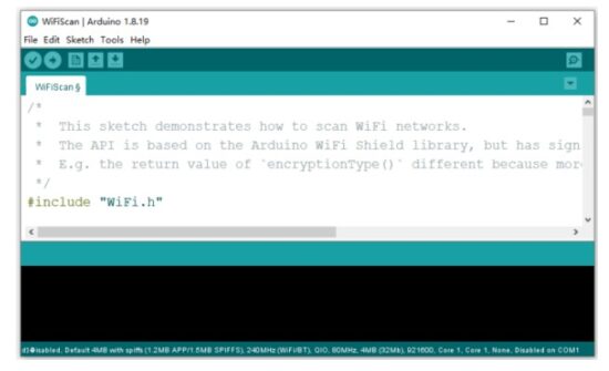
- Open the following example under File > Examples > WiFi
(ESP32) > WiFiScan

- A new sketch opens in your Arduino IDE:
- Press the Upload button in the Arduino IDE. Wait a few seconds while the code compiles and uploads to your board.

- If everything went as expected, you should see a “Done uploading.” message.

- Open the Arduino IDE Serial Monitor at a baud rate of 115200:

- Press the ESP32 on-board Enable button and you should see the networks available near your ESP32:

Troubleshooting
If you try to upload a new sketch to your ESP32 and you get this error message “A fatal error occurred: Failed to connect to ESP32: Timed out… Connecting…“. It means that your ESP32 is not in flashing/uploading mode.
Having the right board name and COM por selected, follow these steps:
Hold-down the “BOOT” button in your ESP32 board
- Press the “Upload” button in the Arduino IDE to upload your sketch:

- After you see the “Connecting….” message in your Arduino IDE, release the finger from the “BOOT” button:

- After that, you should see the “Done uploading” message
That’s it. Your ESP32 should have the new sketch running. Press the “ENABLE” button to restart the ESP32 and run the new uploaded sketch.
You’ll also have to repeat that button sequence every time you want to upload a new sketch.
Project 1 ESP32 Inputs Outputs
In this getting started guide you’ll learn how to read digital inputs like a button switch and control digital outputs like an LED using the ESP32 with Arduino IDE.
Prerequisites
We’ll program the ESP32 using Arduino IDE. So, make sure you have the ESP32 boards add-on installed before proceeding:
- Installing ESP32 Add-on in Arduino IDE
ESP32 Control Digital Outputs
First, you need set the GPIO you want to control as an OUTPUT. Use the pinMode() function as follows:
pinMode(GPIO, OUTPUT);
To control a digital output you just need to use the digitalWrite() function, that accepts as arguments, the GPIO (int number) you are referring to, and the state, either HIGH or LOW.
digitalWrite(GPIO, STATE);
All GPIOs can be used as outputs except GPIOs 6 to 11 (connected to the integrated SPI flash) and GPIOs 34, 35, 36 and 39 (input only GPIOs);
Learn more about the ESP32 GPIOs: ESP32 GPIO Reference Guide
ESP32 Read Digital Inputs
First, set the GPIO you want to read as INPUT, using the pinMode() function as follows:
pinMode(GPIO, INPUT);
To read a digital input, like a button, you use the digitalRead() function, that accepts as argument, the GPIO (int number) you are referring to.
digitalRead(GPIO);
All ESP32 GPIOs can be used as inputs, except GPIOs 6 to 11 (connected to the integrated SPI flash).
Learn more about the ESP32 GPIOs: ESP32 GPIO Reference Guide
Project Example
To show you how to use digital inputs and digital outputs, we’ll build a simple project example with a pushbutton and an LED. We’ll read the state of the pushbutton and light up the LED accordingly as illustrated in the following figure.
Parts Required
Here’s a list of the parts to you need to build the circuit:
- ESP32 DEVKIT V1
- 5 mm LED
- 220 Ohm resistor
- Pushbutton
- 10k Ohm resistor
- Breadboard
- Jumper wires
Schematic Diagram
Before proceeding, you need to assemble a circuit with an LED and a pushbutton.
We’ll connect the LED to GPIO 5 and the pushbutton to GPIO 4. Code
Code
Open the code Project_1_ESP32_Inputs_Outputs.ino in arduino IDE
 How the Code Works
In the following two lines, you create variables to assign pins:
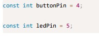 The button is connected to GPIO 4 and the LED is connected to GPIO 5. When using the Arduino IDE with the ESP32, 4 corresponds to GPIO 4 and 5 corresponds to GPIO 5.
Next, you create a variable to hold the button state. By default, it’s 0 (not pressed).
int buttonState = 0;
In the setup(), you initialize the button as an INPUT, and the LED as an OUTPUT.
For that, you use the pinMode() function that accepts the pin you are referring to, and the mode: INPUT or OUTPUT.
pinMode(buttonPin, INPUT);
pinMode(ledPin, OUTPUT);
In the loop() is where you read the button state and set the LED accordingly.
In the next line, you read the button state and save it in the buttonState variable.
As we’ve seen previously, you use the digitalRead() function.
buttonState = digitalRead(buttonPin);
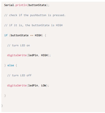
The following if statement, checks whether the button state is HIGH. If it is, it turns the LED on using the digitalWrite() function that accepts as argument the ledPin, and the state HIGH.
if (buttonState == HIGH)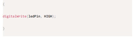 If the button state is not HIGH, you set the LED off. Just set LOW as a second argument to in the digitalWrite() function.
 Uploading the Code
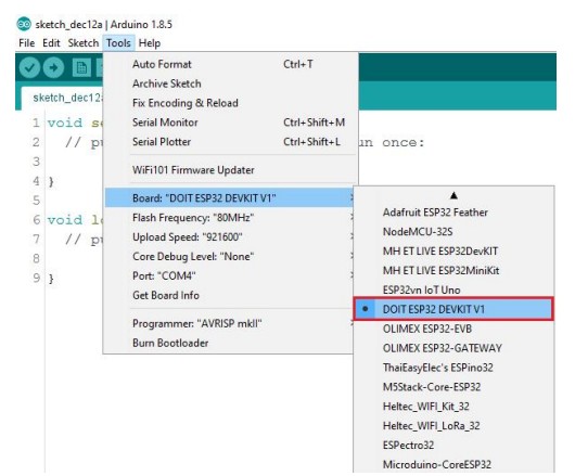
Before clicking the upload button, go to Tools > Board, and select the board :DOIT ESP32 DEVKIT V1 board.
Go to Tools > Port and select the COM port the ESP32 is connected to. Then, press the upload button and wait for the “Done uploading” message.![]() Note:If you see a lot of dots (connecting…__…__) on the debugging window and the “Failed to connect to ESP32: Timed out waiting for packet header” message, that means you need to press the ESP32 on-board BOOT button after the dots
Note:If you see a lot of dots (connecting…__…__) on the debugging window and the “Failed to connect to ESP32: Timed out waiting for packet header” message, that means you need to press the ESP32 on-board BOOT button after the dots
start appearing.Troubleshooting
Demonstration
After uploading the code, test your circuit. Your LED should light up when you press the pushbutton: And turn off when you release it:
Project 2 ESP32 Analog Inputs
This project shows how to read analog inputs with the ESP32 using Arduino IDE.
Analog reading is useful to read values from variable resistors like potentiometers, or analog sensors.
Analog Inputs (ADC)
Reading an analog value with the ESP32 means you can measure varying voltage levels between 0 V and 3.3 V.
The voltage measured is then assigned to a value between 0 and 4095, in which 0 V corresponds to 0, and 3.3 V corresponds to 4095. Any voltage between 0 V and 3.3 V will be given the corresponding value in between. ADC is Non-linear
Ideally, you would expect a linear behavior when using the ESP32 ADC pins.
However, that doesn’t happen. What you’ll get is a behavior as shown in the following chart: This behavior means that your ESP32 is not able to distinguish 3.3 V from 3.2 V.
You’ll get the same value for both voltages: 4095.
The same happens for very low voltage values: for 0 V and 0.1 V you’ll get the same value: 0. You need to keep this in mind when using the ESP32 ADC pins.
analogRead() Function
Reading an analog input with the ESP32 using the Arduino IDE is as simple as using the analogRead() function. It accepts as argument, the GPIO you want to read:
analogRead(GPIO);
Only 15 are available in the DEVKIT V1board (version with 30 GPIOs).
Grab your ESP32 board pinout and locate the ADC pins. These are highlighted with a red border in the figure below. These analog input pins have 12-bit resolution. This means that when you read an analog input, its range may vary from 0 to 4095.
Note: ADC2 pins cannot be used when Wi-Fi is used. So, if you’re using Wi-Fi and you’re having trouble getting the value from an ADC2 GPIO, you may consider using an ADC1 GPIO instead, that should solve your problem.
To see how everything ties together, we’ll make a simple example to read an analog value from a potentiometer.
Parts Required
For this example, you need the following parts:
- ESP32 DEVKIT V1 Board
- Potentiometer
- Breadboard
- Jumper wires
Schematic
Wire a potentiometer to your ESP32. The potentiometer middle pin should be connected to GPIO 4. You can use the following schematic diagram as a reference. Code
Code
We’ll program the ESP32 using Arduino IDE, so make sure you have the ESP32 add-on installed before proceeding:(If you have already done this step, you can skip to the next step.)
Installing ESP32 Add-on in Arduino IDE
Open the code Project_2_ESP32_Inputs_Outputs.ino in arduino IDE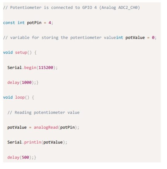 This code simply reads the values from the potentiometer and prints those values in the Serial Monitor.
In the code, you start by defining the GPIO the potentiometer is connected to. In this example, GPIO 4.![]() In the setup(), initialize a serial communication at a baud rate of 115200.
In the setup(), initialize a serial communication at a baud rate of 115200.![]() In the loop(), use the analogRead() function to read the analog input from the potPin.
In the loop(), use the analogRead() function to read the analog input from the potPin.![]() Finally, print the values read from the potentiometer in the serial monitor.
Finally, print the values read from the potentiometer in the serial monitor.![]() Upload the code provided to your ESP32. Make sure you have the right board and COM port selected in the Tools menu.
Upload the code provided to your ESP32. Make sure you have the right board and COM port selected in the Tools menu.
Testing the Example
After uploading the code and pressing the ESP32 reset button, open the Serial Monitor at a baud rate of 115200. Rotate the potentiometer and see the values changing.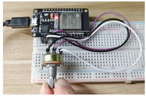 The maximum value you’ll get is 4095 and the minimum value is 0.
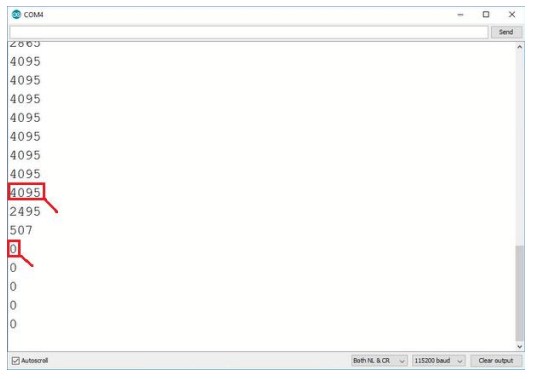
Wrapping Up
In this article you’ve learned how to read analog inputs using the ESP32 with the Arduino IDE. In summary:
- The ESP32 DEVKIT V1 DOIT board (version with 30 pins) has 15 ADC pins you can use to read analog inputs.
- These pins have a resolution of 12 bits, which means you can get values from 0 to 4095.
- To read a value in the Arduino IDE, you simply use the analogRead() function.
- The ESP32 ADC pins don’t have a linear behavior. You’ll probably won’t be able to distinguish between 0 and 0.1V, or between 3.2 and 3.3V. You need to keep that in mind when using the ADC pins.
Project 3 ESP32 PWM(Analog Output)
In this tutorial we’ll show you how to generate PWM signals with the ESP32 using Arduino IDE. As an example we’ll build a simple circuit that dims an LED using the LED PWM controller of the ESP32. ESP32 LED PWM Controller
The ESP32 has a LED PWM controller with 16 independent channels that can be configured to generate PWM signals with different properties.
Here’s the steps you’ll have to follow to dim an LED with PWM using the Arduino IDE:
- First, you need to choose a PWM channel. There are 16 channels from 0 to 15.
- Then, you need to set the PWM signal frequency. For an LED, a frequency of 5000 Hz is fine to use.
- You also need to set the signal’s duty cycle resolution: you have resolutions from 1 to 16 bits. We’ll use 8-bit resolution, which means you can control the LED brightness using a value from 0 to 255.
- Next, you need to specify to which GPIO or GPIOs the signal will appear upon. For that you’ll use the following function:
ledcAttachPin(GPIO, channel)
This function accepts two arguments. The first is the GPIO that will output the signal, and the second is the channel that will generate the signal. - Finally, to control the LED brightness using PWM, you use the following function:
ledcWrite(channel, dutycycle)
This function accepts as arguments the channel that is generating the PWM signal, and the duty cycle.
Parts Required
To follow this tutorial you need these parts:
- ESP32 DEVKIT V1 Board
- 5mm LED
- 220 Ohm resistor
- Breadboard
- Jumper wires
Schematic
Wire an LED to your ESP32 as in the following schematic diagram. The LED should be connected to GPIO 4. Note: you can use any pin you want, as long as it can act as an output. All pins that can act as outputs can be used as PWM pins. For more information about the ESP32 GPIOs, read: ESP32 Pinout Reference: Which GPIO pins should you use?
Code
We’ll program the ESP32 using Arduino IDE, so make sure you have the ESP32 add-on installed before proceeding:(If you have already done this step, you can skip to the next step.)
Installing ESP32 Add-on in Arduino IDE
Open the code Project_3_ESP32_PWM.ino in arduino IDE
 You start by defining the pin the LED is attached to. In this case the LED is attached to GPIO 4.
![]() Then, you set the PWM signal properties. You define a frequency of 5000 Hz, choose channel 0 to generate the signal, and set a resolution of 8 bits. You can choose other properties, different than these, to generate different PWM signals.
Then, you set the PWM signal properties. You define a frequency of 5000 Hz, choose channel 0 to generate the signal, and set a resolution of 8 bits. You can choose other properties, different than these, to generate different PWM signals.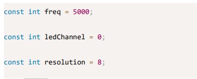 In the setup(), you need to configure LED PWM with the properties you’ve defined earlier by using the ledcSetup() function that accepts as arguments, the ledChannel, the frequency, and the resolution, as follows:
 Next, you need to choose the GPIO you’ll get the signal from. For that use the ledcAttachPin() function that accepts as arguments the GPIO where you want to get the signal, and the channel that is generating the signal. In this example, we’ll get the signal in the ledPin GPIO, that corresponds to GPIO 4. The channel that generates the signal is the ledChannel, that corresponds to channel 0.
![]() In the loop, you’ll vary the duty cycle between 0 and 255 to increase the LED brightness.
In the loop, you’ll vary the duty cycle between 0 and 255 to increase the LED brightness. And then, between 255 and 0 to decrease the brightness.
 To set the brightness of the LED, you just need to use the ledcWrite() function that accepts as arguments the channel that is generating the signal, and the duty cycle.
![]() As we’re using 8-bit resolution, the duty cycle will be controlled using a value from 0 to 255. Note that in the ledcWrite() function we use the channel that is generating the signal, and not the GPIO.
As we’re using 8-bit resolution, the duty cycle will be controlled using a value from 0 to 255. Note that in the ledcWrite() function we use the channel that is generating the signal, and not the GPIO.
Testing the Example
Upload the code to your ESP32. Make sure you have the right board and COM port selected. Look at your circuit. You should have a dimmer LED that increases and decreases brightness.
Project 4 ESP32 PIR Motion Sensor
This project shows how to detect motion with the ESP32 using a PIR motion sensor.The buzzer will sound an alarm when motion is detected, and stop the alarm when no motion is detected for a preset time (such as 4 seconds)
How HC-SR501 Motion Sensor Works
.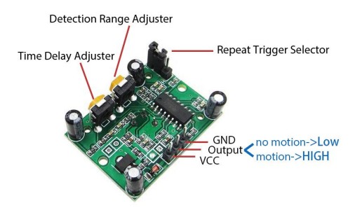 The working principle of HC-SR501 sensor is based on the change of the infrared radiation on the moving object.To be detected by the HC-SR501 sensor, the object must meet two requirements:
- The object is emitting the infrared way.
- The object is moving or shaking
So:
lf an object is emitting the infrared ray but NoT moving (e.g, a person stands still without moving), it is NoT detected by the sensor.
lf an object is moving but NoT emitting the infrared ray (e.g, robot or vehicle), it is NOT detected by the sensor.
Introducing Timers
In this example we’ll also introduce timers. We want the LED to stay on for a predetermined number of seconds after motion is detected. Instead of using a delay() function that blocks your code and doesn’t allow you to do anything else for a determined number of seconds, we should use a timer. The delay() function
You should be familiar with the delay() function as it is widely used. This function is pretty straightforward to use. It accepts a single int number as an argument.
This number represents the time in milliseconds the program has to wait until moving on to the next line of code.![]() When you do delay(1000) your program stops on that line for 1 second.
When you do delay(1000) your program stops on that line for 1 second.
delay() is a blocking function. Blocking functions prevent a program from doing anything else until that particular task is completed. If you need multiple tasks to occur at the same time, you cannot use delay().
For most projects you should avoid using delays and use timers instead.
The millis() function
Using a function called millis() you can return the number of milliseconds that have passed since the program first started.![]() Why is that function useful? Because by using some math, you can easily verify how much time has passed without blocking your code.
Why is that function useful? Because by using some math, you can easily verify how much time has passed without blocking your code.
Parts Required
To follow this tutorial you need the following parts
- ESP32 DEVKIT V1 Board
- PIR motion sensor (HC-SR501)
- Active Buzzer
- Jumper wires
- Breadboard
Schematic Note: The working voltage of HC-SR501 is 5V. Use the Vin pin to power it.
Code
Before proceeding with this tutorial you should have the ESP32 add-on installed in your Arduino IDE. Follow one of the following tutorials to install the ESP32 on the Arduino IDE, if you haven’t already.(If you have already done this step, you can skip to the next step.)
Installing ESP32 Add-on in Arduino IDE
Open the code Project_4_ESP32_PIR_Motion_Sensor.ino in arduino IDE.
Demonstration
Upload the code to your ESP32 board. Make sure you have the right board and COM port selected.Upload code reference steps.
Open the Serial Monitor at a baud rate of 115200. Move your hand in front of the PIR sensor. The buzzer should turn on, and the message is printed in the Serial Monitor saying “Motion detected!Buzzer alarm”.
After 4 seconds the buzzer should turn off.
Project 5 ESP32 Switch Web Server
In this project you’ll create a standalone web server with an ESP32 that controls outputs (two LEDs) using the Arduino IDE programming environment. The web server is mobile responsive and can be accessed with any device that as a browser on the local network. We’ll show you how to create the web server and how the code works step-by-step.
Project Overview
Before going straight to the project, it is important to outline what our web server will do, so that it is easier to follow the steps later on.
- The web server you’ll build controls two LEDs connected to the ESP32 GPIO 26 and GPIO 27;
- You can access the ESP32 web server by typing the ESP32 IP address on a browser in the local network;
- By clicking the buttons on your web server you can instantly change the state of each LED.
Parts Required
For this tutorial you’ll need the following parts:
- ESP32 DEVKIT V1 Board
- 2x 5mm LED
- 2x 200 Ohm resistor
- Breadboard
- Jumper wires
Schematic
Start by building the circuit. Connect two LEDs to the ESP32 as shown in the following schematic diagram – one LED connected to GPIO 26, and the other to GPIO 27.
Note: We’re using the ESP32 DEVKIT DOIT board with 36 pins. Before assembling the circuit, make sure you check the pinout for the board you’re using. Code
Code
Here we provide the code that creates the ESP32 web server. Open the code Project_5_ESP32_Switch _Web_Server.ino in arduino IDE, but don’t upload it yet. You need to make some changes to make it work for you.
We’ll program the ESP32 using Arduino IDE, so make sure you have the ESP32 add-on installed before proceeding:(If you have already done this step, you can skip to the next step.)
Installing ESP32 Add-on in Arduino IDE
Setting Your Network Credentials
You need to modify the following lines with your network credentials: SSID and password. The code is well commented on where you should make the changes.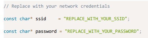 Uploading the Code
Now, you can upload the code and and the web server will work straight away.
Follow the next steps to upload code to the ESP32:
- Plug your ESP32 board in your computer;
- In the Arduino IDE select your board in Tools > Board (in our case we’re using the ESP32 DEVKIT DOIT board);
- Select the COM port in Tools > Port.

- Press the Upload button in the Arduino IDE and wait a few seconds while the code compiles and uploads to your board.

- Wait for the “Done uploading” message.

Finding the ESP IP Address
After uploading the code, open the Serial Monitor at a baud rate of 115200. Press the ESP32 EN button (reset). The ESP32 connects to Wi-Fi, and outputs the ESP IP address on the Serial Monitor. Copy that IP address, because you need it to access the ESP32 web server.
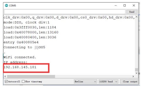 Accessing the Web Server
To access the web server, open your browser, paste the ESP32 IP address, and you’ll see the following page.
Note: Your browser and ESP32 should be connected to the same LAN.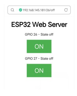 If you take a look at the Serial Monitor, you can see what’s happening on the background. The ESP receives an HTTP request from a new client (in this case, your browser).
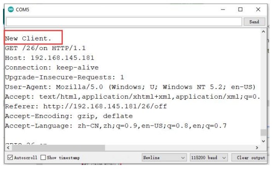 You can also see other information about the HTTP request.
Demonstration
Now you can test if your web server is working properly. Click the buttons to control the LEDs. At the same time, you can take a look at the Serial Monitor to see what’s going on in the background. For example, when you click the button to turn GPIO 26 ON, ESP32 receives a request on the /26/on URL.
 When the ESP32 receives that request, it turns the LED attached to GPIO 26 ON and updates its state on the web page.
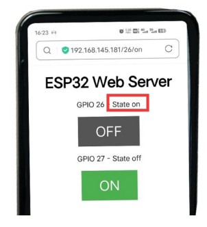 The button for GPIO 27 works in a similar way. Test that it is working properly.
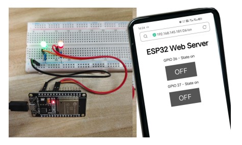
How the Code Works
In this section will take a closer look at the code to see how it works.
The first thing you need to do is to include the WiFi library.![]() As mentioned previously, you need to insert your ssid and password in the following lines inside the double quotes.
As mentioned previously, you need to insert your ssid and password in the following lines inside the double quotes.![]() Then, you set your web server to port 80.
Then, you set your web server to port 80.![]() The following line creates a variable to store the header of the HTTP request:
The following line creates a variable to store the header of the HTTP request:![]() Next, you create auxiliar variables to store the current state of your outputs. If you want to add more outputs and save its state, you need to create more variables.
Next, you create auxiliar variables to store the current state of your outputs. If you want to add more outputs and save its state, you need to create more variables.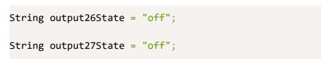 You also need to assign a GPIO to each of your outputs. Here we are using GPIO 26 and GPIO 27. You can use any other suitable GPIOs.
![]() setup()
setup()
Now, let’s go into the setup(). First, we start a serial communication at a baud rate of 115200 for debugging purposes.![]() You also define your GPIOs as OUTPUTs and set them to LOW.
You also define your GPIOs as OUTPUTs and set them to LOW. The following lines begin the Wi-Fi connection with WiFi.begin(ssid, password), wait for a successful connection and print the ESP IP address in the Serial Monitor.
 loop()
In the loop() we program what happens when a new client establishes a connection with the web server.
The ESP32 is always listening for incoming clients with the following line: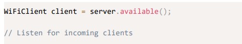 When a request is received from a client, we’ll save the incoming data. The while loop that follows will be running as long as the client stays connected. We don’t recommend changing the following part of the code unless you know exactly what you are doing.

![]() The next section of if and else statements checks which button was pressed in your web page, and controls the outputs accordingly. As we’ve seen previously, we make a request on different URLs depending on the button pressed.
The next section of if and else statements checks which button was pressed in your web page, and controls the outputs accordingly. As we’ve seen previously, we make a request on different URLs depending on the button pressed.
![]() For example, if you’ve press the GPIO 26 ON button, the ESP32 receives a request on the /26/ON URL (we can see that that information on the HTTP header on the Serial Monitor). So, we can check if the header contains the expression GET /26/on. If it contains, we change the output26state variable to ON, and the ESP32 turns the LED on.
For example, if you’ve press the GPIO 26 ON button, the ESP32 receives a request on the /26/ON URL (we can see that that information on the HTTP header on the Serial Monitor). So, we can check if the header contains the expression GET /26/on. If it contains, we change the output26state variable to ON, and the ESP32 turns the LED on.
This works similarly for the other buttons. So, if you want to add more outputs, you should modify this part of the code to include them.
Displaying the HTML web page
The next thing you need to do, is creating the web page. The ESP32 will be sending a response to your browser with some HTML code to build the web page.
The web page is sent to the client using this expressing client.println(). You should enter what you want to send to the client as an argument.
The first thing we should send is always the following line, that indicates that we are sending HTML.![]() Then, the following line makes the web page responsive in any web browser.
Then, the following line makes the web page responsive in any web browser. And the following is used to prevent requests on the favicon. – You don’t need to worry about this line.
![]()
Styling the Web Page
Next, we have some CSS text to style the buttons and the web page appearance.
We choose the Helvetica font, define the content to be displayed as a block and aligned at the center. We style our buttons with the #4CAF50 color, without border, text in white color, and with this padding: 16px 40px. We also set the text-decoration to none, define the font size, the margin, and the cursor to a pointer.
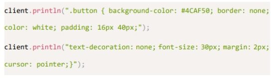 We also define the style for a second button, with all the properties of the button we’ve defined earlier, but with a different color. This will be the style for the off button.
Setting the Web Page First Heading
In the next line you can set the first heading of your web page. Here we have “ESP32 Web Server”, but you can change this text to whatever you like. Displaying the Buttons and Corresponding State
Then, you write a paragraph to display the GPIO 26 current state. As you can see we use the output26State variable, so that the state updates instantly when this variable changes.![]() Then, we display the on or the off button, depending on the current state of the GPIO. If the current state of the GPIO is off, we show the ON button, if not, we display the OFF button.
Then, we display the on or the off button, depending on the current state of the GPIO. If the current state of the GPIO is off, we show the ON button, if not, we display the OFF button.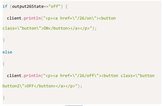 We use the same procedure for GPIO 27.
Closing the Connection
Finally, when the response ends, we clear the header variable, and stop the connection with the client with client.stop().
Wrapping Up
In this tutorial we’ve shown you how to build a web server with the ESP32. We’ve shown you a simple example that controls two LEDs, but the idea is to replace those LEDs with a relay, or any other output you want to control.
Project 6 RGB LED Web Server
In this project we’ll show you how to remotely control an RGB LED with an ESP32 board using a web server with a color picker.
Project Overview
Before getting started, let’s see how this project works:
- The ESP32 web server displays a color picker.
- When you chose a color, your browser makes a request on a URL that contains the R, G, and B parameters of the selected color.
- Your ESP32 receives the request and splits the value for each color parameter.
- Then, it sends a PWM signal with the corresponding value to the GPIOs that are controlling the RGB LED.
How do RGB LEDs work?
In a common cathode RGB LED, all three LEDs share a negative connection (cathode).All included in the kit are common-cathode RGB. How to create different colors?
With an RGB LED you can, of course, produce red, green, and blue light, and by configuring the intensity of each LED, you can produce other colors as well.
For example, to produce purely blue light, you’d set the blue LED to the highest intensity and the green and red LEDs to the lowest intensity. For a white light, you’d set all three LEDs to the highest intensity.
Mixing colors
To produce other colors, you can combine the three colors in different intensities. To adjust the intensity of each LED you can use a PWM signal.
Because the LEDs are very close to each other, our eyes see the result of the combination of colors, rather than the three colors individually.
To have an idea on how to combine the colors, take a look at the following chart.
This is the simplest color mixing chart, but gives you an idea how it works and how to produce different colors. Parts Required
For this project you need the following parts:
- ESP32 DEVKIT V1 Board
- RGB LED
- 3x 220 ohm resistors
- Jumper wires
- Breadboard
Schematic Code
Code
We’ll program the ESP32 using Arduino IDE, so make sure you have the ESP32 add-on installed before proceeding:(If you have already done this step, you can skip to the next step.)
- Installing ESP32 Add-on in Arduino IDE
After assembling the circuit, Open the code
Project_6_RGB_LED_Web_Server.ino in arduino IDE.
Before uploading the code, don’t forget to insert your network credentials so that the ESP can connect to your local network.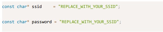 How the code works
The ESP32 sketch uses the WiFi.h library.![]() The following lines define string variables to hold the R, G, and B parameters from the request.
The following lines define string variables to hold the R, G, and B parameters from the request. The next four variables are used to decode the HTTP request later on.
![]() Create three variables for the GPIOs that will control the strip R, G, and B parameters. In this case we’re using GPIO 13, GPIO 12, and GPIO 14.
Create three variables for the GPIOs that will control the strip R, G, and B parameters. In this case we’re using GPIO 13, GPIO 12, and GPIO 14. These GPIOs need to output PWM signals, so we need to configure the PWM properties first. Set the PWM signal frequency to 5000 Hz. Then, associate a PWM channel for each color
 And finally, set the resolution of the PWM channels to 8-bit
![]() In the setup(), assign the PWM properties to the PWM channels
In the setup(), assign the PWM properties to the PWM channels Attach the PWM channels to the corresponding GPIOs
 The following code section displays the color picker in your web page and makes a request based on the color you’ve picked.
![]()

 When you pick a color, you receive a request with the following format.
![]()
So, we need to split this string to get the R, G, and B parameters. The parameters are saved in redString, greenString, and blueString variables and can have values between 0 and 255.
![]() To control the strip with the ESP32, use the ledcWrite() function to generate PWM signals with the values decoded from the HTTP request.
To control the strip with the ESP32, use the ledcWrite() function to generate PWM signals with the values decoded from the HTTP request. Note: learn more about PWM with ESP32: Project 3 ESP32 PWM(Analog Output)
To control the strip with the ESP8266, we just need to use
the analogWrite() function to generate PWM signals with the values decoded from the HTPP request.
analogWrite(redPin, redString.toInt());
analogWrite(greenPin, greenString.toInt());
analogWrite(bluePin, blueString.toInt())
Because we get the values in a string variable, we need to convert them to integers using the toInt() method.
Demonstration
After inserting your network credentials, select the right board and COM port and upload the code to your ESP32.Upload code reference steps.
After uploading, open the Serial Monitor at a baud rate of 115200 and press the ESP Enable/Reset button. You should get the board IP address. Open your browser and insert the ESP IP address. Now, use the color picker to choose a color for the RGB LED.
Then, you need to press the “Change Color” button for the color to take effect. To turn off the RGB LED , select the black color.
The strongest colors (at the top of the color picker), are the ones that will produce better results.
Project 7 ESP32 Relay Web Server
Using a relay with the ESP32 is a great way to control AC household appliances remotely. This tutorial explains how to control a relay module with the ESP32.
We’ll take a look at how a relay module works, how to connect the relay to the ESP32 and build a web server to control a relay remotely.
Introducing Relays
A relay is an electrically operated switch and like any other switch, it that can be turned on or off, letting the current go through or not. It can be controlled with low voltages, like the 3.3V provided by the ESP32 GPIOs and allows us to control high voltages like 12V, 24V or mains voltage (230V in Europe and 120V in the US). On the left side, there are two sets of three sockets to connect high voltages, and the pins on the right side (low-voltage) connect to the ESP32 GPIOs.
Mains Voltage Connections The relay module shown in the previous photo has two connectors, each with three sockets: common (COM), Normally Closed (NC), and Normally Open (NO).
- COM: connect the current you want to control (mains voltage).
- NC (Normally Closed): the normally closed configuration is used when you want the relay to be closed by default. The NC are COM pins are connected, meaning the current is flowing unless you send a signal from the ESP32 to the relay module to open the circuit and stop the current flow.
- NO (Normally Open): the normally open configuration works the other way around: there is no connection between the NO and COM pins, so the circuit is broken unless you send a signal from the ESP32 to close the circuit.
Control Pins The low-voltage side has a set of four pins and a set of three pins. The first set consists of VCC and GND to power up the module, and input 1 (IN1) and input 2 (IN2) to control the bottom and top relays, respectively.
If your relay module only has one channel, you’ll have just one IN pin. If you have four channels, you’ll have four IN pins, and so on.
The signal you send to the IN pins, determines whether the relay is active or not. The relay is triggered when the input goes below about 2V. This means that you’ll have the following scenarios:
- Normally Closed configuration (NC):
- HIGH signal – current is flowing
- LOW signal – current is not flowing
- Normally Open configuration (NO):
- HIGH signal – current is not flowing
- LOW signal – current in flowing
You should use a normally closed configuration when the current should be flowing most of the times, and you only want to stop it occasionally.
Use a normally open configuration when you want the current to flow occasionally (for example, turn on a lamp occasionally).
Power Supply Selection The second set of pins consists of GND, VCC, and JD-VCC pins.
The JD-VCC pin powers the electromagnet of the relay. Notice that the module has a jumper cap connecting the VCC and JD-VCC pins; the one shown here is yellow, but yours may be a different color.
With the jumper cap on, the VCC and JD-VCC pins are connected. That means the relay electromagnet is directly powered from the ESP32 power pin, so the relay module and the ESP32 circuits are not physically isolated from each other.
Without the jumper cap, you need to provide an independent power source to power up the relay’s electromagnet through the JD-VCC pin. That configuration physically isolates the relays from the ESP32 with the module’s built-in optocoupler, which prevents damage to the ESP32 in case of electrical spikes.
Schematic Warning: Use of high voltage power supplies may cause serious injury.
Therefore, 5mm LEDs are used instead of high supply voltage bulbs in the experiment. If you’re not familiar with mains voltage ask someone who is to help you out. While programming the ESP or wiring your circuit make sure everything is disconnected from mains voltage. Installing the Library for ESP32
To build this web server, we use the ESPAsyncWebServer library and AsyncTCP Library.
Installing the ESPAsyncWebServer library
Follow the next steps to install the ESPAsyncWebServer library:
- Click here to download the ESPAsyncWebServer library. You should have
a .zip folder in your Downloads folder - Unzip the .zip folder and you should get ESPAsyncWebServer-master folder
- Rename your folder from ESPAsyncWebServer-master to ESPAsyncWebServer
- Move the ESPAsyncWebServer folder to your Arduino IDE installation libraries folder
Alternatively, in your Arduino IDE, you can go to Sketch > Include
Library > Add .ZIP library… and select the library you’ve just downloaded.
Installing the AsyncTCP Library for ESP32
The ESPAsyncWebServer library requires the AsyncTCP library to work. Follow
the next steps to install that library:
- Click here to download the AsyncTCP library. You should have a .zip folder in your Downloads folder
- Unzip the .zip folder and you should get AsyncTCP-master folder
1. Rename your folder from AsyncTCP-master to AsyncTCP
3. Move the AsyncTCP folder to your Arduino IDE installation libraries folder
4. Finally, re-open your Arduino IDE
Alternatively, in your Arduino IDE, you can go to Sketch > Include
Library > Add .ZIP library… and select the library you’ve just downloaded.
Code
We’ll program the ESP32 using Arduino IDE, so make sure you have the ESP32 add-on installed before proceeding:(If you have already done this step, you can skip to the next step.)
Installing ESP32 Add-on in Arduino IDE
After installing the required libraries, Open the code Project_7_ESP32_Relay_Web_Server.ino in arduino IDE.
Before uploading the code, don’t forget to insert your network credentials so that the ESP can connect to your local network. Demonstration
After making the necessary changes, upload the code to your ESP32.Upload code reference steps.
Open the Serial Monitor at a baud rate of 115200 and press the ESP32 EN button to get its IP address.Then, open a browser in your local network and type the ESP32 IP address to get access to the web server.
Open the Serial Monitor at a baud rate of 115200 and press the ESP32 EN button to get its IP address.Then, open a browser in your local network and type the ESP32 IP address to get access to the web server.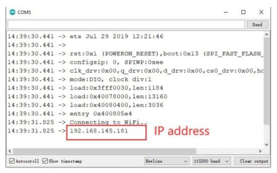 Note: Your browser and ESP32 should be connected to the same LAN.
You should get something as follows with as two buttons as the number of relays you’ve defined in your code. Now, you can use the buttons to control your relays using your smartphone.
Project_8_Output_State_Synchronization_ Web_Server
This Project shows how to control the ESP32 or ESP8266 outputs using a web server and a physical button simultaneously. The output state is updated on the web page whether it is changed via physical button or web server.
Project Overview
Let’s take a quick look at how the project works. The ESP32 or ESP8266 hosts a web server that allows you to control the state of an output;
- The current output state is displayed on the web server;
- The ESP is also connected to a physical pushbutton that controls the same output;
- If you change the output state using the physical puhsbutton, its current state is also updated on the web server.
In summary, this project allows you to control the same output using a web server and a push button simultaneously. Whenever the output state changes, the web server is updated.
Parts Required
Here’s a list of the parts to you need to build the circuit:
- ESP32 DEVKIT V1 Board
- 5 mm LED
- 220Ohm resistor
- Pushbutton
- 10k Ohm resistor
- Breadboard
- Jumper wires
Schematic Installing the Library for ESP32
To build this web server, we use the ESPAsyncWebServer library and AsyncTCP Library.(If you have already done this step, you can skip to the next step.)
Installing the ESPAsyncWebServer library
Follow the next steps to install the ESPAsyncWebServer library:
- Click here to download the ESPAsyncWebServer library. You should have
a .zip folder in your Downloads folder - Unzip the .zip folder and you should get ESPAsyncWebServer-master folder
- Rename your folder from ESPAsyncWebServer-master to ESPAsyncWebServer
- Move the ESPAsyncWebServer folder to your Arduino IDE installation libraries folder
Alternatively, in your Arduino IDE, you can go to Sketch > Include
Library > Add .ZIP library… and select the library you’ve just downloaded.
Installing the AsyncTCP Library for ESP32
The ESPAsyncWebServer library requires the AsyncTCP library to work. Follow the next steps to install that library:
- Click here to download the AsyncTCP library. You should have a .zip folder in your Downloads folder
- Unzip the .zip folder and you should get AsyncTCP-master folder
- Rename your folder from AsyncTCP-master to AsyncTCP
- Move the AsyncTCP folder to your Arduino IDE installation libraries folder
- Finally, re-open your Arduino IDE
Alternatively, in your Arduino IDE, you can go to Sketch > Include
Library > Add .ZIP library… and select the library you’ve just downloaded.
Code
We’ll program the ESP32 using Arduino IDE, so make sure you have the ESP32 add-on installed before proceeding:(If you have already done this step, you can skip to the next step.)
Installing ESP32 Add-on in Arduino IDE
After installing the required libraries, Open the code
Project_8_Output_State_Synchronization_Web_Server.ino in arduino IDE.
Before uploading the code, don’t forget to insert your network credentials so that the ESP can connect to your local network.
How the Code Works
Button State and Output State
The ledState variable holds the LED output state. For default, when the web server starts, it is LOW.![]()
The buttonState and lastButtonState are used to detect whether the pushbutton was pressed or not. Button (web server)
We didn’t include the HTML to create the button on the the index_html variable.
That’s because we want to be able to change it depending on the current LED state that can also be changed with the pushbutton.
So, we’ve create a placeholder for the button %BUTTONPLACEHOLDER% that will be replaced with HTML text to create the button later on the code (this is done in the processor() function). processor()
The processor() function replaces any placeholders on the HTML text with actual values. First, it checks whether the HTML texts contains any
placeholders %BUTTONPLACEHOLDER%.![]() Then, call theoutputState() function that returns the current output state. We save it in the outputStateValue variable.
Then, call theoutputState() function that returns the current output state. We save it in the outputStateValue variable.![]() After that, use that value to create the HTML text to display the button with the right state:
After that, use that value to create the HTML text to display the button with the right state: HTTP GET Request to Change Output State (JavaScript)
When you press the button, thetoggleCheckbox() function is called. This function will make a request on different URLs to turn the LED on or off.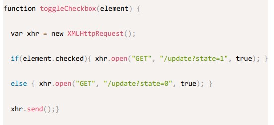 To turn on the LED, it makes a request on the /update?state=1 URL:
![]() Otherwise, it makes a request on the /update?state=0 URL.
Otherwise, it makes a request on the /update?state=0 URL.
HTTP GET Request to Update State (JavaScript)
To keep the output state updated on the web server, we call the following function that makes a new request on the /state URL every second.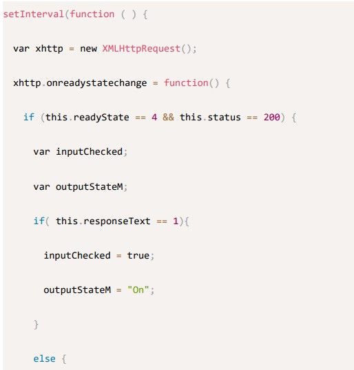
 Handle Requests
Then, we need to handle what happens when the ESP32 or ESP8266 receives requests on those URLs.
When a request is received on the root /URL, we send the HTML page as well as the processor.![]()
![]() The following lines check whether you received a request on the /update?state=1 or /update?state=0 URL and changes the ledState accordingly.
The following lines check whether you received a request on the /update?state=1 or /update?state=0 URL and changes the ledState accordingly.
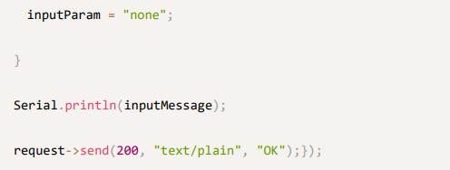 When a request is received on the /state URL, we send the current output state:
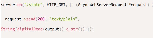 loop()
In the loop(), we debounce the pushbutton and turn the LED on or off depending on the value of the ledState variable.![]() Demonstration
Demonstration
Upload the code to your ESP32 board.Upload code reference steps.
Then, open the Serial Monitor at a baud rate of 115200. Press the on-board EN/RST button to get is IP address. Open a browser on your local network, and type the ESP IP address. You should have access to the web server as shown below.
Note: Your browser and ESP32 should be connected to the same LAN. You can toggle the button on the web server to turn the LED on.
 You can also control the same LED with the physical pushbutton. Its state will always be updated automatically on the web server.
Project 9 ESP32 DHT11 Web Server
In this project, you’ll learn how to build an asynchronous ESP32 web server with the DHT11 that displays temperature and humidity using Arduino IDE.
Prerequisites
The web server we’ll build updates the readings automatically without the need to refresh the web page.
With this project you’ll learn:
- How to read temperature and humidity from DHT sensors;
- Build an asynchronous web server using the ESPAsyncWebServer library;
- Update the sensor readings automatically without the need to refresh the web page.
Asynchronous Web Server
To build the web server we’ll use the ESPAsyncWebServer library that provides an easy way to build an asynchronous web server. Building an asynchronous web server has several advantages as mentioned in the library GitHub page, such as:
- “Handle more than one connection at the same time”;
- “When you send the response, you are immediately ready to handle other connections while the server is taking care of sending the response in the background”;
- “Simple template processing engine to handle templates”;
Parts Required
To complete this tutorial you need the following parts:
- ESP32 development board
- DHT11 Module
- Breadboard
- Jumper wires
Schematic Installing Libraries
You need to install a couple of libraries for this project:
- The DHT and the Adafruit Unified Sensor Driver libraries to read from the DHT sensor.
- ESPAsyncWebServer and Async TCP libraries to build the asynchronous web server.
Follow the next instructions to install those libraries:
Installing the DHT Sensor Library
To read from the DHT sensor using Arduino IDE, you need to install the DHT sensor library. Follow the next steps to install the library.
- Click here to download the DHT Sensor library. You should have a .zip folder in your Downloads folder
- Unzip the .zip folder and you should get DHT-sensor-library-master folder
- Rename your folder from DHT-sensor-library-master to DHT_sensor
- Move the DHT_sensor folder to your Arduino IDE installation libraries folder
- Finally, re-open your Arduino IDE
Installing the Adafruit Unified Sensor Driver
You also need to install the Adafruit Unified Sensor Driver library to work with the DHT sensor. Follow the next steps to install the library.
- Click here to download the Adafruit Unified Sensor library. You should have a .zip folder in your Downloads folder
- Unzip the .zip folder and you should get Adafruit_sensor-master folder
- Rename your folder from Adafruit_sensor-master to Adafruit_sensor
- Move the Adafruit_sensor folder to your Arduino IDE installation libraries folder
- Finally, re-open your Arduino IDE
Installing the ESPAsyncWebServer library
Follow the next steps to install the ESPAsyncWebServer library:
- Click here to download the ESPAsyncWebServer library. You should have
a .zip folder in your Downloads folder - Unzip the .zip folder and you should
get ESPAsyncWebServer-master folder - Rename your folder from ESPAsyncWebServer-master to ESPAsyncWebServer
- Move the ESPAsyncWebServer folder to your Arduino IDE installation libraries folder
Installing the Async TCP Library for ESP32
The ESPAsyncWebServer library requires the AsyncTCP library to work. Follow the next steps to install that library:
- Click here to download the AsyncTCP library. You should have a .zip folder in your Downloads folder
- Unzip the .zip folder and you should get AsyncTCP-master folder
- Rename your folder from AsyncTCP-master to AsyncTCP
- Move the AsyncTCP folder to your Arduino IDE installation libraries folder
- Finally, re-open your Arduino IDE
Code
We’ll program the ESP32 using Arduino IDE, so make sure you have the ESP32 add-on installed before proceeding:(If you have already done this step, you can skip to the next step.)
Installing ESP32 Add-on in Arduino IDE
After installing the required libraries, Open the code
Project_9_ESP32_DHT11_Web_Server.ino in arduino IDE.
Before uploading the code, don’t forget to insert your network credentials so that the ESP can connect to your local network. How the Code Works
In the following paragraphs we’ll explain how the code works. Keep reading if you want to learn more or jump to the Demonstration section to see the final result.
Importing libraries
First, import the required libraries. The WiFi, ESPAsyncWebServer and the ESPAsyncTCP are needed to build the web server. The Adafruit_Sensor and the DHT libraries are needed to read from the DHT11 or DHT22 sensors.![]()
 Variables definition
Define the GPIO that the DHT data pin is connected to. In this case, it’s connected to GPIO 4.![]() Then, select the DHT sensor type you’re using. In our example, we’re using the DHT22. If you’re using another type, you just need to uncomment your sensor and comment all the others.
Then, select the DHT sensor type you’re using. In our example, we’re using the DHT22. If you’re using another type, you just need to uncomment your sensor and comment all the others.![]()
Instantiate a DHT object with the type and pin we’ve defined earlier.![]() Create an AsyncWebServer object on port 80.
Create an AsyncWebServer object on port 80.![]() Read Temperature and Humidity Functions
Read Temperature and Humidity Functions
We’ve created two functions: one to read the temperature We’ve created two functions: one to read the temperature (readDHTTemperature()) and the other to read humidity (readDHTHumidity()).
 Getting sensor readings is as simple as using Getting sensor readings is as simple as using the readTemperature() and readHumidity()methods on the dht object.
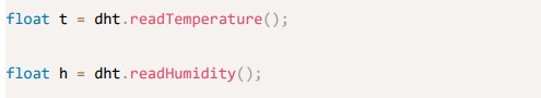 We also have a condition that returns two dashes (–) in case the sensor fails to get the readings.
 The readings are returned as string type. To convert a float to a string, use the String() function
![]() By default, we’re reading the temperature in Celsius degrees. To get the temperature in Fahrenheit degrees, comment the temperature in Celsius and uncomment the temperature in Fahrenheit, so that you have the following:
By default, we’re reading the temperature in Celsius degrees. To get the temperature in Fahrenheit degrees, comment the temperature in Celsius and uncomment the temperature in Fahrenheit, so that you have the following:![]()
 Upload the Code
Now, upload the code to your ESP32. Make sure you have the right board and COM port selected.Upload code reference steps.
After uploading, open the Serial Monitor at a baud rate of 115200. Press the ESP32 reset button. The ESP32 IP address should be printed in the serial monitor. Demonstration
Open a browser and type the ESP32 IP address. Your web server should display the latest sensor readings.
Note: Your browser and ESP32 should be connected to the same LAN.
Notice that the temperature and humidity readings are updated automatically without the need to refresh the web page.
Project_10_ESP32_OLED_Display
This project shows how to use the 0.96 inch SSD1306 OLED display with ESP32 using Arduino IDE.
Introducing 0.96 inch OLED Display
The OLED display that we’ll use in this tutorial is the SSD1306 model: a monocolor, 0.96 inch display with 128×64 pixels as shown in the following figure. The OLED display doesn’t require backlight, which results in a very nice contrast in dark environments. Additionally, its pixels consume energy only when they are on, so the OLED display consumes less power when compared to other displays.
Because the OLED display uses I2C communication protocol, wiring is very simple. You can use the following table as a reference.
| OLED Pin | ESP32 |
| Vin | 3.3V |
| GND | GND |
| SCL | GPIO 22 |
| SDA | GPIO 21 |
Schematic Installing SSD1306 OLED Library – ESP32
There are several libraries available to control the OLED display with the ESP32.
In this tutorial we’ll use two Adafruit libraries: Adafruit_SSD1306 library and Adafruit_GFX library.
Follow the next steps to install those libraries.
- Open your Arduino IDE and go to Sketch > Include Library > Manage Libraries. The Library Manager should open.
- Type “SSD1306” in the search box and install the SSD1306 library from Adafruit.

- After installing the SSD1306 library from Adafruit, type “GFX” in the search box and install the library.

- After installing the libraries, restart your Arduino IDE.
Code
After installing the required libraries, Open the Project_10_ESP32_OLED_Display.ino in arduino IDE. code
We’ll program the ESP32 using Arduino IDE, so make sure you have the ESP32 add-on installed before proceeding: (If you have already done this step, you can skip to the next step.)
Installing ESP32 Add-on in Arduino IDE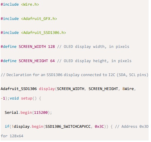

 How the Code Works
Importing libraries
First, you need to import the necessary libraries. The Wire library to use I2C and the Adafruit libraries to write to the display: Adafruit_GFX and Adafruit_SSD1306.
![]() Initialize the OLED display
Initialize the OLED display
Then, you define your OLED width and height. In this example, we’re using a 128×64 OLED display. If you’re using other sizes, you can change that in the SCREEN_WIDTH, and SCREEN_HEIGHT variables. Then, initialize a display object with the width and height defined earlier with I2C communication protocol (&Wire).
![]() The (-1) parameter means that your OLED display doesn’t have a RESET pin. If your OLED display does have a RESET pin, it should be connected to a GPIO. In that case, you should pass the GPIO number as a parameter.
The (-1) parameter means that your OLED display doesn’t have a RESET pin. If your OLED display does have a RESET pin, it should be connected to a GPIO. In that case, you should pass the GPIO number as a parameter.
In the setup(), initialize the Serial Monitor at a baud raute of 115200 for debugging purposes.![]() Initialize the OLED display with the begin() method as follows:
Initialize the OLED display with the begin() method as follows:![]()
 This snippet also prints a message on the Serial Monitor, in case we’re not able to connect to the display.
![]() In case you’re using a different OLED display, you may need to change the OLED address. In our case, the address is 0x3C.
In case you’re using a different OLED display, you may need to change the OLED address. In our case, the address is 0x3C.![]() After initializing the display, add a two second delay, so that the OLED has enough time to initialize before writing text:
After initializing the display, add a two second delay, so that the OLED has enough time to initialize before writing text:![]() Clear display, set font size, color and write text
Clear display, set font size, color and write text
After initializing the display, clear the display buffer with the clearDisplay() method:![]()
Before writing text, you need to set the text size, color and where the text will be displayed in the OLED.
Set the font size using the setTextSize() method:![]() Set the font color with the setTextColor() method:
Set the font color with the setTextColor() method:
WHITE sets white font and black background.
Define the position where the text starts using the setCursor(x,y) method. In this case, we’re setting the text to start at the (0,0) coordinates – at the top left corner.![]() Finally, you can send the text to the display using the println() method, as follows
Finally, you can send the text to the display using the println() method, as follows![]() Then, you need to call the display() method to actually display the text on the screen.
Then, you need to call the display() method to actually display the text on the screen.![]()
The Adafruit OLED library provides useful methods to easily scroll text.
- startscrollright(0x00, 0x0F): scroll text from left to right
- startscrollleft(0x00, 0x0F): scroll text from right to left
- startscrolldiagright(0x00, 0x07): scroll text from left bottom corner to right upper corner startscrolldiagleft(0x00, 0x07): scroll text from right bottom corner to left upper corner
Upload the Code
Now, upload the code to your ESP32.Upload code reference steps.
After uploading the code, the OLED will display scrolling text.
![]()
Documents / Resources
 |
LAFVIN ESP32 Basic Starter Kit [pdf] Instruction Manual ESP32 Basic Starter Kit, ESP32, Basic Starter Kit, Starter Kit |