zencontrol zc-ss-2sw Smart Switch w/2 Buttons

Product range
| Order code | Description |
| zc-ss-2sw-blk | Smart switch with 2 buttons to suit 84 mm wall mount, black |
| zc-ss-2sw-wht | Smart switch with 2 buttons to suit 84 mm wall mount, white |
| zc-ss-2sw-eu-blk | Smart switch with 2 buttons to suit 84 mm wall mount, black |
| zc-ss-2sw-eu-wht | Smart switch with 2 buttons to suit 84 mm wall mount, white |
Specifications
| Supply | 220 – 240 V |
| Supply current | 4 mA |
| Control system | IEC62386-104 over Thread® / DALI-2 |
| Radio support | IEEE 802.15.4 |
| Frequency band | 2.4 GHz |
| Max radio tx power | +8 dBm |
| DALI line current | 2 mA |
| Wiring | 1 – 4 mm2 Strip 8 – 10 mm |
| Operating temperature | 0 to 55°C |
| Material | PC UV stabilised, toughened glass, aluminium |
| Ingress protection | IP20 |
Safety information
- This product must only be installed by a licensed electrician.
- Before commencing installation turn off and isolate the electrical supply.
- There are no user serviceable parts, attempting to service any part of the product will void the warranty
- DALI is not SELV and as such should be treated as LV.
- As the installer, it is your responsibility to ensure you comply to all relevant building and safety codes. Refer to application standards for the relevant rules.
- Isolate electrical supply before removing faceplate.
Circuit-board is NOT isolated.
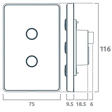
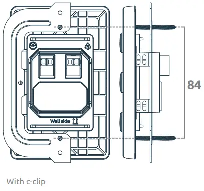
Dimensions (mm)
| zc-ss-2sw | Fixing centres | 84 mm | Dimensions | W75 / H117 / D34 mm |
 |
 |
|||
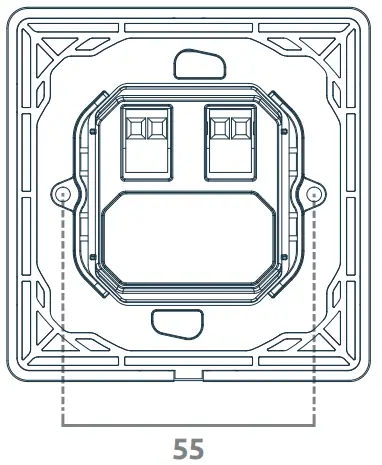
| zc-ss-2sw-eu | Fixing centres | 55 mm D | Dimensions | W86 / H86 / D34 mm |
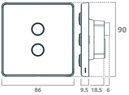 |
 |
|||
System overview: modes
- 104 mode is enabled after the device has been added to a 104 application controller such as zc-iot-fc.
Wireless switch
IEC 62386-301

- 104 + 101 Bridge mode is enabled after the device has been added to a 104 controller and a 101 power supply has been connected to the DALI terminals.

- 101 mode is enabled after a 101 power supply has been connected to the DALI terminal and the device has not been added to a 104 application controller.

Installation
Remove the product from the box and inspect it for any damage. If you believe the product to be damaged or otherwise unsound, do not install the product. Please pack it back into its box and return it to the place of purchase for replacement.
If the product is satisfactory, proceed with the installation:
- Ensure safety warnings are adhered to.
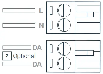
- Optional: Connect the two DALI terminals to the DALI line ensuring wiring regulations are followed. DALI is not polarised. DALI is not SELV and as such must be treated as LV. Do not connect DALI to any mains voltages.
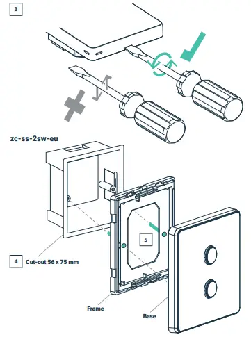
- Remove front plate by inserting a screwdriver (min. 5.5pt) into receptacle at the bottom of the frame. Twist left, twist right, to release cover, do not lever.
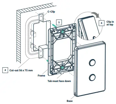
- Cut-out the hole, insert wallbox if applicable.
- Insert provided screws into frame and attach to pre-mounted wallbox/c-clip.
- Not applicable to eu versions. Latch cover on top of frame to clip base back into frame, attached on the wall.
zc-ss-2sw
Wiring diagram
Input configuration
Wire preparation
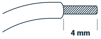

![]() Ensure each terminal is lined up with correct marking on the product label
Ensure each terminal is lined up with correct marking on the product label
Configuration
- By default the device is configured with 1/2/3 control device instances with LED indicator. Actual function is dependant on the configuration of a DALI-2 application controllers connected to the DALI line, or the Wireless application controller.
- By default the device will configure its mode of operation depending on what has been commissioned.
ECD operating mode
- 128 (0x80) Bridge mode (default): Device acts as a bridge between Thread 104 interface and DALI devices connected via 101 interface
- 129 (0x81) Beacon mode: Device broadcasts Bluetooth beacons and communicates via 104 interface if Thread network is commissioned otherwise via 101 interface. For more information on how to configure Beacons visit support. zencontrol.com
- 130 (0x82) Bridge disabled: Device communicates via both 104+101 interface, however, bridge mode is disabled (i.e. Devices connected on the 101 interface will not be available on the Thread 104 system)
Customer Support
Notice

For more information on compliant software see our website zencontrol.com
![]()
© zencontrol
![]()
Documents / Resources
 |
zencontrol zc-ss-2sw Smart Switch w/2 Buttons [pdf] Owner's Manual zc-ss-2sw Smart Switch w 2 Buttons, zc-ss-2sw, Smart Switch w 2 Buttons, w 2 Buttons, Buttons |


