STMicroelectronics UM3399 STM32Cube WiSE Radio Code Generator
Product Usage Instructions
- The STM32CubeWiSE-RadioCodeGenerator application requires at least 2 Gbytes of RAM, USB ports, and Adobe Acrobat reader 6.0.
- Extract the content of the stm32wise-cgwin.zip file into a temporary directory.
- Launch the STM32CubeWiSE-RadioCodeGenerator_Vx.x.x.exe file and follow the on-screen instructions.
- The STM32CubeWiSE-RadioCodeGenerator SW package files are organized into folders including ‘app’ and ‘examples’.
- To build a flowgraph in STM32CubeWiSE-RadioCodeGenerator:
- Add SeqActions to the flowgraph using the toolbar or global menu.
- Connect SeqActions to the entry point and to each other by drawing action transition arrows.
- Navigate the flow graph by dragging actions and adding action transitions as needed.
Introduction
- This document describes the STM32CubeWiSE-RadioCodeGenerator (STM32CubeWiSEcg) SW package with the STM32WL3x MRSUBG sequencer code generator.
- STM32CubeWiSE-RadioCodeGenerator is a PC application that is used to build a flowgraph that defines which transceiver actions to execute under which condition, using the MRSUBG sequencer driver.
- STM32WL3x Sub-GHz radio contains this sequencer, which is a state-machine-like mechanism that allows for autonomous management of RF transfers, without any need for CPU intervention.
- If CPU intervention is required, interrupts can be defined. Transceiver actions can be arranged in a flow graph. In this document, the individual transceiver actions are referred to as SeqActions.
- However, source code is not the best representation for flowgraphs, since it conceals their logical and temporal structure.
- STM32CubeWiSE-RadioCodeGenerator addresses this issue by providing a graphical method to build flowgraphs and then exporting the generated flowgraphs as C source code for integration into user applications.
- The flowgraph definition is stored in the microcontroller RAM in the form of:
- A set of ActionConfiguration RAM tables, linked to each other using pointers. These pointers define the SeqActions, that is, the type of action (for example, transmission, reception, abort), as well as SeqAction-specific radio parameters and conditions for action transmissions.
- A unique GlobalConfiguration RAM table. This defines the entry point of the flowgraph (the first SeqAction to execute), as well as some default flag values and common radio parameters.
- Radio parameters, which can be configured individually for each SeqAction, are stored in one of the dynamic registers, whose contents are part of the ActionConfiguration RAM table. Radio parameters that are fixed over the whole execution of the flowgraph (unless they are modified during a CPU interrupt), are stored in static registers, whose contents are part of the global configuration RAM table.

General information
Licensing
This document describes software that runs on the STM32WL3x Arm® Cortex ® -M0+ based microcontroller.
Note: Arm is a registered trademark of Arm Limited (or its subsidiaries) in the US and/or elsewhere.
Related documents
Table 1. Document references
| Number | Reference | Title |
| [1] | RM0511 | STM32WL30xx/31xx/33xx Arm® based sub-GHz MCUs |
Getting started
- This section describes all of the system requirements to run STM32CubeWiSE-RadioCodeGenerator.
- It also details the software package installation procedure.
System requirements
The STM32CubeWiSE-RadioCodeGenerator application has the following minimum requirements:
- PC with an Intel® or AMD® processor running the Microsoft® Windows 10 operating system
- At least 2 Gbytes of RAM
- USB ports
- Adobe Acrobat reader 6.0
STM32CubeWiSE-RadioCodeGenerator SW package setup
Perform tthe following steps:
- Extract the content of the stm32wise-cgwin.zip file into a temporary directory.
- Extract and launch the STM32CubeWiSE-RadioCodeGenerator_Vx.x.x.exe file and follow the on-screen instructions.
STM32CubeWiSE-RadioCodeGenerator SW package files
The STM32CubeWiSE-RadioCodeGenerator SW package files are organized into the following folders:
- app: contains STM32CubeWiSE-RadioCodeGenerator.exe
- examples: this folder is organized into the following subfolders:
- code: this folder contains the flowgraphs example already exported as C code, ready to be injected into an application project
- flowgraphs: this folder stores some examples scenarios of autonomous MRSUBG sequencer operations
Release notes and license files are located in the root folder.
STM32CubeWiSE-RadioCodeGenerator software description
- This section describes the main functions of the STM32CubeWiSE-RadioCodeGenerator application. To run this utility, click on the STM32CubeWiSE-RadioCodeGenerator icon.

After launching STM32CubeWiSE-RadioCodeGenerator, the main application window appears. It consists of:
- A global menu and toolbar
- The visual drag-and-drop representation of the flowgraph
- The SeqAction configuration section (only visible if a SeqAction is currently being edited)
Building a flowgraph
Basics
Flowgraphs are built in two steps:
- Add SeqActions to the flowgraph. This can be done using the “Add Action” button in the toolbar, using the global menu (Edit → Add Action) or with the “Ctrl+A” shortcut.
- Connect SeqActions to the entry point and to each other by drawing action transition arrows.
The conditions under which these transitions occur are defined later (see Section 3.2.1: Control flow).
Navigating the flowgraph, dragging actions
By dragging the checkerboard background of the flowgraph with the mouse pointer (left click), the viewport on the flowgraph can be adjusted. The mouse scroll wheel can be used to zoom in and out. Clicking anywhere on an action (except for the output ports, the delete button and the edit button) to select an action. Actions can be arranged in the flowgraph by dragging them with the left mouse button.
Adding action transitions
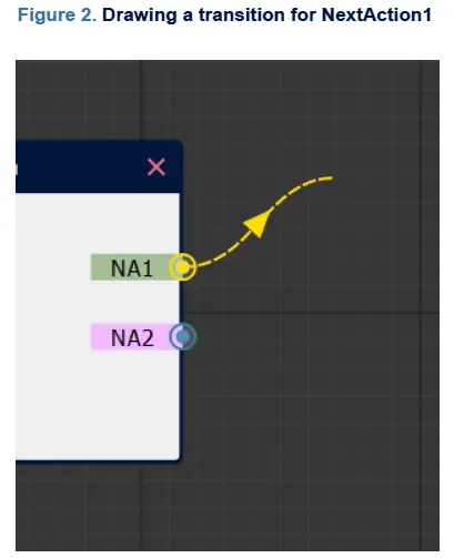
- As shown in Figure 2, each action has two “output port”, called NextAction1 (NA1) and NextAction2 (NA2), which can be connected to SeqActions that are executed after the action has been completed. For example, NextAction1 could be used to execute some action if the current action was successful and NextAction2 could be triggered in case of failure.
- To create an action transition, hover the mouse pointer over one of the output ports, press the left mouse button and move the mouse pointer to drag a transition arrow. Move the mouse pointer over the input port on the left of some other SeqAction and release the left mouse button to make the connection permanent. To remove an action transition, just repeat the steps for creating an action transition, but release the left mouse button somewhere over the checkerboard background.
- If an output (NextAction1, NextAction2) is left unconnected, the sequencer terminates if this next action is triggered.
- Make sure to also connect the “Entry Point” to some SeqAction’s input port. This SeqAction is the first to be executed as soon as the sequencer is triggered.
Editing and deleting actions

- SeqActions can be edited by clicking on the pencil button on the top left of SeqAction. It can be deleted by clicking on the red cross on the top right (see Figure 3). Deleting a SeqAction also removes any incoming and outgoing action transitions.
SeqAction configuration
SeqActions can be configured through a tabbed configuration interface accessible through the pencil button on the top left of each action in the flowgraph. This interface essentially configures the contents of the ActionConfiguration RAM table for the particular action, consisting of both control flow-related configuration options as well as the dynamic register contents. The dynamic register contents can either be configured manually with complete control over every register value (see Section 3.2.3: Advanced radio configuration) or through a simplified interface (seeSection 3.2.2: Basic radio configuration ). The simplified interface should be sufficient for almost all use cases.
Control flow
The control flow tab (see Figure 4) contains some basic configuration options such as action name and action timeout interval. The action name is not only used for display in the flowgraph but is also carried over to the generated source code.


- The control flow tab (see Figure 4) contains some basic configuration options such as action name and action timeout interval. The action name is not just used for display in the flowgraph but also carried over to the generated source code.
- Most importantly, the control flow tab configures the condition on which a transition to NextAction1 / NextAction2 depends on as well as transition interval and flags. The transition condition can be configured by clicking on the button labeled “…”, which makes the mask selection dialog shown in Figure 5 appear. The transition interval modified the NextAction1Interval / NextAction2Interval property of the RAM table. Refer to the STM32WL3x reference manual [1] for more information on the meaning of this interval and the significance of the SleepEn / ForceReload / ForceClear flags.
- Furthermore, a short description of the SeqAction block can be added on this tab. This description is only used for documentation purposes and carried over to the generated source code as a source code comment.
Basic radio configuration

The basic radio configuration tab can be subdivided into three parts:
- A section at the top where two of the most important parameters of any action are configured: the command to execute (TX, RX, NOP, SABORT, and so on) and, if applicable, the length of the packet to transfer.
- A section on the left where the actual radio parameters such as: carrier frequency, data rate, modulation properties, data buffer thresholds and timers are configured.
- A section on the right where the CPU interrupts can be individually enabled. An interrupt handler is generated for each of the ticked interrupts. This basically configures the contents of the RFSEQ_IRQ_ENABLE register.
Refer to the STM32WL3x reference manual [1] for the meaning of the various radio parameters.
Advanced radio configuration

- If the configuration options exposed through the basic radio configuration tab (Section 3.2.2: Basic radio configuration) are insufficient, the advanced STM32WL3x radio configuration tab allows the setting of arbitrary dynamic register contents. The advanced configuration tab is enabled by ticking the Advanced Configuration checkbox to the top right of the tabbed configuration interface.
- It is not possible to use both basic and advanced configurations at the same time, the user must select one or the other. However, it is of course also possible to manually edit the generated source code afterwards and to add potentially missing configuration options.
Global configuration dialog
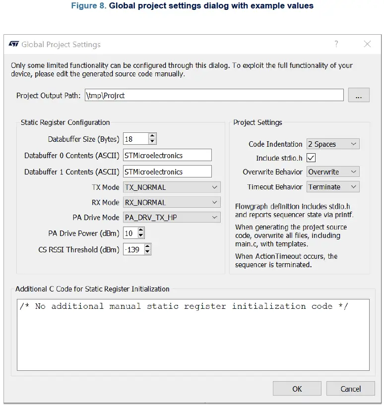
- The “Global Project Settings” dialog can be accessed through the “Global Settings” toolbar button. The dialog contains both configuration options for the static register contents as well as additional project settings. Note that only a small fraction of static register configuration options can be configured through this dialog. These options are only provided to speed up application prototyping applications with STM32CubeWiSE-RadioCodeGenerator.
- It is usually expected that the static register contents are set up in the application’s manually-written source code.
- The meaning of the other project settings is explained in the dialog itself.
- Additional C code that is inserted just before creating the Global Configuration RAM table from the static register contents may also be provided. This field may be used to set up static register values that are inaccessible through the provided static register configuration mask.
Code generation
The flowgraph can be translated into a complete project C source code by pressing the Generate Code button in the toolbar. The generated project folder does not contain project files for IAR, Keil®, or GCC. These files must be added manually to the STMWL3x project.
This is the generated project folder structure:
Project folder
- inc
- SequencerFlowgraph.h: header file for SequencerFlowgraph.c, static. Do not edit this.
- stm32wl3x_hal_conf.h: STM32WL3x HAL configuration file, static.
- src
- SequencerFlowgraph.c: flowgraph definition. This is the important file that uses the sequencer driver to define the global-configuration and action-configuration RAM tables. Autogenerated, do not edit.
- main.c: Project main file that demonstrates how to load and apply the flow-graph definition. Static, modify this as needed.
- To edit main.c or stm32wl3x_hal_conf.h, select overwrite behavior Keep in the project settings. This way, only SequencerFlowgraph.c gets overwritten.
How to import generated code into a CubeMX example
To import a project generated by STM32CubeWiSE-RadioCodeGenerator into a CubeMX example (MRSUBG_Skeleton), it is necessary to follow the following steps:
- Open the folder containing the files generated by STM32CubeWiSE-RadioCodeGenerator and copy “Inc” and “Src” folders.
- Paste the two folders on the “MRSUBG_Skeleton” folder overwriting the two already present.
- Open the “MRSUBG_Skeleton” project in one of the following IDEs:
- EWARM
- MDK-ARM
- STM32CubeIDE
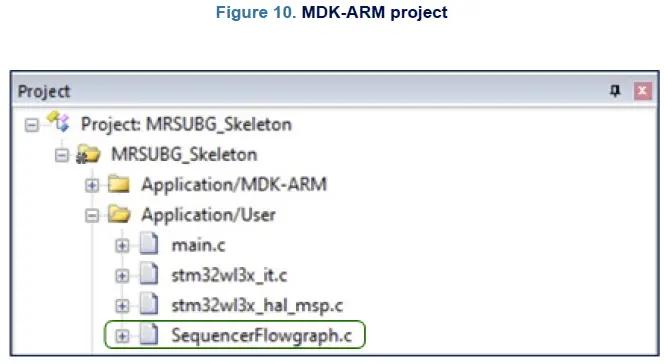
- Inside the “MRSUBG_Skeleton” project, add the “SequencerFlowghraph.c” file:
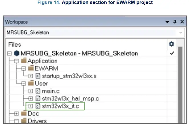
- For an EWARM project, the path to add the file is the following: MRSUBG_Skeleton\Application\User

- For an MDK-ARM project, the path to add the file is the following: MRSUBG_Skeleton\Application/User
- For an STM32CubeIDE project, the path to add the file is the same:
MRSUBG_Skeleton\Application\User
- For an EWARM project, the path to add the file is the following: MRSUBG_Skeleton\Application\User
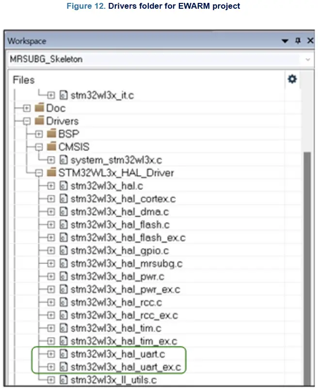
- Inside the MRSUBG_Skeleton project, add stm32wl3x_hal_uart.c and stm32wl3x_hal_uart_ex.c files to the following path: MRSUBG_Skeleton\Drivers\STM32WL3x_HAL_Driver. The path is the same for all IDEs. The two files are located on Firmware\Drivers\STM32WL3x_HAL_Driver\Src.
- To use COM features, stm32wl3x_nucleo_conf.h file, located on Firmware\Projects\NUCLEOWL33CC\ Examples\MRSUBG\MRSUBG_Skeleton\Inc, must be modified setting USE_BSP_COM_FEATURE and USE_COM_LOG to 1U:

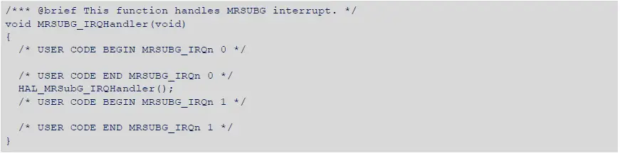
- Copy the following code into “stm32wl3x_it.c”, located in MRSUBG_Skeleton\Application\User.
Flowgraph examples
- Four example flowgraphs are provided alongside the source code. These examples may be loaded into STM32CubeWiSE-RadioCodeGenerator by clicking the “Load” button in the toolbar.
AutoACK_RX

- The Auto-ACK demo illustrates how two STM32WL3x devices can automatically talk to each other with minimal CPU intervention, with the help of the sequencer hardware.
- This flowgraph implements the behavior (Auto-Transmit-ACK) of device A. In device A, the sequencer is initialized in a receiving state (WaitForMessage), in which it waits for a message to arrive.
- Once a valid message arrives, the sequencer automatically transitions into a transmit state (TransmitACK), in which an ACK packet is sent as a response, without CPU intervention. Once this is finished, the sequencer is reset into its initial WaitForMessage state.
- This flowgraph implements the same behavior as the MRSUBG_SequencerAutoAck_Rx example from the Examples\MRSUBG folder of the STM32Cube WL3 Software package. If AutoACK_RX is flashed on one device
A, and AutoACK_TX is flashed on some device, B, the two devices send messages back and forth, as in a ping-pong game.
AutoACK_TX
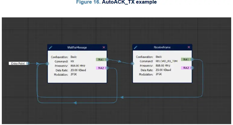
- The “Auto-ACK” demo illustrates how two STM32WL3x devices can automatically talk to each other with minimal CPU intervention with the help of the sequencer hardware.
- This flowgraph implements the behavior (“Auto-Wait-for-ACK”) of device B. In device B, the sequencer is initialized in a transmitting state (TransmitMessage), in which it transmits a message. Once the transmission is finished, it automatically transitions into a receiving state where it waits for an acknowledgment from device A (WaitForACK). Once a valid acknowledgment arrives, the sequencer is reset into its initial TransmitMessage state and the whole process starts again. In case no ACK is received within 4 seconds, a timeout is triggered and the sequencer returns to state TransmitMessage anyway.
- This flowgraph implements the same behavior as the “MRSUBG_SequencerAutoAck_Tx” example from the Examples\MRSUBG folder of the STM32Cube WL3 Software package. If AutoACK_RX is flashed on one device, A, and AutoACK_TX is flashed on some other device, B, the two devices send messages back and forth, as in a ping-pong game.
Listen before talk (LBT)
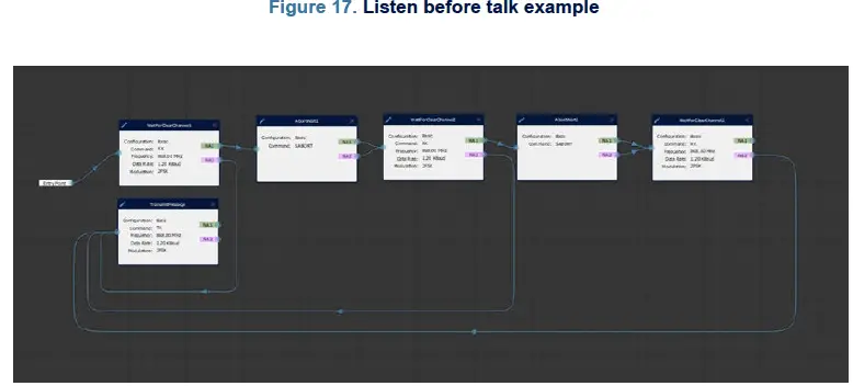
- This example is taken from the STM32WL3x reference manual [1]. Refer to that manual for further details of this example.
Sniff mode

- This example is taken from the STM32WL3x reference manual [1]. Refer to that manual for further details of this example.
Revision history
Table 2. Document revision history
| Date | Version | Changes |
| 21-Nov-2024 | 1 | Initial release. |
| 10-Feb-2025 | 2 | Updated device name to scope STM32WL3x. |
IMPORTANT NOTICE – READ CAREFULLY
- STMicroelectronics NV and its subsidiaries (“ST”) reserve the right to make changes, corrections, enhancements, modifications, and improvements to ST products and/or to this document at any time without notice. Purchasers should obtain the latest relevant information on ST products before placing orders. ST products are sold pursuant to ST’s terms and conditions of sale in place at the time of order acknowledgment.
- Purchasers are solely responsible for the choice, selection, and use of ST products and ST assumes no liability for application assistance or the design of purchasers’ products.
- No license, express or implied, to any intellectual property right is granted by ST herein.
- Resale of ST products with provisions different from the information set forth herein shall void any warranty granted by ST for such product.
- ST and the ST logo are trademarks of ST. For additional information about ST trademarks, refer to www.st.com/trademarks. All other product or service names are the property of their respective owners.
- Information in this document supersedes and replaces information previously supplied in any prior versions of this document.
- © 2025 STMicroelectronics – All rights reserved
FAQ
- Q: What are the minimum system requirements for STM32CubeWiSE-RadioCodeGenerator?
- A: The minimum system requirements include at least 2 Gbytes of RAM, USB ports, and Adobe Acrobat reader 6.0.
- Q: How can I set up the STM32CubeWiSE-RadioCodeGenerator software package?
- A: To set up the software package, extract the content of the provided zip file into a temporary directory and launch the executable file following the on-screen instructions.
Documents / Resources
 |
STMicroelectronics UM3399 STM32Cube WiSE Radio Code Generator [pdf] User Manual UM3399, UM3399 STM32 Cube WiSE Radio Code Generator, UM3399, STM32, Cube WiSE Radio Code Generator, Radio Code Generator, Code Generator, Generator |