RAMSET AUTOMATIC GATE SYSTEM RAM3100DC-PE High Traffic Swinging Gate Operators

Specifications
Gate Safety Important Safety Instructions
General Specifications:
- UL Gate Classification: RAM 3000, RAM 3100, RAM 30-30 DC
- Electrical Connection: Included
- Wire Gauge: Refer to manual for specific requirements
Product Usage Instructions
Installation
- Factory Wiring Diagram: Follow the provided diagram for the correct installation.
- M.E.P. Quick Setup Guide: Use this guide for Monitored Entrapment Protection setup.
- B.O.M. (BILL OF MATERIALS): Refer to the Bill of Materials section for required parts.
Installation Specs
- RAM 3000s/ 30-30 Concrete Pad Construction: Follow specific instructions for concrete pad construction.
- Gate Travel Adjustment: Adjust as needed for proper gate operation.
- Emergency Release: Familiarize yourself with the emergency release mechanism.
- Operation Location/ Arm Lengths: Determine optimal location and arm lengths for the gate operation.
- Compact/ Custom Installations: Follow guidelines for compact or custom installations.
Entrapment & Safety Protection
- Entrapment Protection Types: Understand and implement the different types of protection mentioned in the manual.
- Monitored Photo Eye Wiring (EMX-NIR-250-325): Connect the photo eye wiring as per instructions.
- Entrapment Protection Area: Identify and secure the entrapment protection area as described.
FAQ
- What wire gauge should I use for the electrical connection?
- The specific wire gauge required will depend on the individual components and setup. Refer to the wire gauge section in the manual for detailed information.
- How do I adjust the gate travel?
- To adjust the gate travel, follow the provided instructions in the Gate Travel Adjustment section of the manual. It typically involves making adjustments to the gate mechanism.
- What is Monitored Entrapment Protection (M.E.P.)?
- M.E.P. is a safety feature that continuously monitors for potential entrapment situations and triggers safety measures to prevent accidents. Refer to the M.E.P. Quick Setup Guide for more information on setting it up.
Warning ONLY A QUALIFIED EXPERIENCED GATE TECHNICIAN SHOULD INSTALL, MAINTAIN OR SERVICE THIS OR ANY GATE OPERATOR
IMPORTANT SAFETY INSTRUCTIONS
WARNING – To reduce the risk of injury or death:
- READ AND FOLLOW ALL INSTRUCTIONS.
- Never let children operate or play with gate controls. Keep the remote control away from children.
- Always keep people and objects away from the gate. NO ONE SHOULD CROSS THE PATH OF THE MOVING GATE.
- Test the gate operator monthly. The gate MUST reverse on contact with a rigid object or stop when an object activates the non-contact sensors. After adjusting the force or the limit of travel, retest the gate operator. Failure to adjust and retest the gate operator properly can increase the risk of injury or death.
- Use the emergency release only when the gate is not moving.
- KEEP GATES PROPERLY MAINTAINED. Read the user’s manual. Have only qualified service persons make repairs to gate hardware.
- The entrance is for vehicles only. Pedestrians must use separate entrance.
- SAVE THESE INSTRUCTIONS.
GENERAL SPECIFICATIONS
| MODEL | DCRAM3000 | DC RAM 3100 | DC RAM 3030 |
| MAXGATE WEIGHT | 2,000 lbs. | 2,500 lbs. | 3,000 lbs. |
| MAX GATE LENGTH | 22′ | 22′ | 20′ |
| GATE SPEED | 90° in 15 seconds (varies with arms and speed dial) | 90° in 15 seconds (varies with arms and speedily) | 90° in 15 seconds (varies with arms and speed dial) |
| MOTOR | Brushless
24VOC, 25A, 520W |
Brushless
24VOC, 25A, 520W |
Brushless
24VOC, 25A, 520W |
| DUTY CYCLE | CONTINUOUS | CONTINUOUS | CONTINUOUS |
| AC POWER OPTIONS | 115V, 60Hz
230V, 60 Hz |
115V,60Hz
230V, 60 Hz |
115V, 60Hz
230V, 60 Hz |
| BATTERIES | (2) 7Ah 12V Batteries | (2) 7Ah12V Batteries | (2) 7Ah12V Batteries |
| COVER DIMENSIONS | 23″ X 18″ X 28.5″ | 23″ X 18″ X 28.5″ | 23.5″ X 17.5″ X 28.5″ |
NOTE: All measurements and capabilities in this manual are for standard installations. All other types of installations may reduce the capabilities and measurements in this manual.
The speed of the gate depends on the geometry of the arms and the speed dial (see page 17).
IMPORTANT SAFETY REQUIREMENTS BY UL STANDARDS
- Install the gate operator only when:
- The operator Is appropriate for the construction of the gate and the usage Class of the gate,
- All openings of a horizontal slide gate are
guarded or screened from the bottom of the gate for a minimum of 1.83 m (6 ft) above the ground to prevent a 57.2 mm (2-1/4 inch) diameter sphere from passing through the openings anywhere in the gate, and in that portion of the adjacent fence that the gate covers in the open position, - All areas of the moving vertical pivot gate panel from the bottom of the gate to the top of the gate or a minimum of 1.83 m (72 in) above grade, whichever is less, that pass by a fixed stationary object, and in the area of the adjacent fence that the gate covers during the travel of the gate, shall be designed, guarded or screened to prevent a 57 mm (2-1/4 in) diameter sphere from passing through such areas.
- All exposed pinch points are eliminated or guarded, and
- Guarding is supplied for exposed rollers.
- The operator instructions shall list the maximum number of open and close entrapment protection devices capable of being connected to the operator.
- The operator is intended for installation only on gates used for vehicles. Pedestrians must be supplied with a separate access opening. The pedestrian access opening shall be designed to promote pedestrian usage. Locate the gate such that persons will not come in contact with the vehicular gate during the entire path of travel of the vehicular gate.
- The gate must be installed in a location so that enough clearance is supplied between the gate and adjacent structures when opening and closing to reduce the risk of entrapment. Swinging gates shall not open into public access areas.
- The gate must be properly installed and work freely in both directions prior to the installation of the gate operator. Do not over-tighten the operator clutch or pressure relief valve to compensate for an improperly installed, improperly functioning, or damaged gate.
- For gate operators utilizing Type D protection:
- The gate operator controls must be placed so that the user has full view of the gate area when the gate is moving,
- The placard as required by 62.1.6 shall be placed adjacent to the controls,
- An automatic closing device (such as a timer, loop sensor, or similar device) shall not be employed, and
- No other activation device shall be connected.
- Permanently mounted controls intended for user activation must be located at least 1.83 m (6ft) away from any moving part of the gate and where the user is prevented from reaching over, under, around or through the gate to operate the controls.
- Exception: Emergency access controls only accessible by authorized personnel (e.g. fire police, EMS) may be placed at any location in the 1 ine-of-sight of the gate.
- The Stop and/or Reset button must be located in the line-of-sight of the gate. Activation of the reset control shall not cause the operator to start.
- A minimum of two (2) WARNING SIGNS shall be installed, in the area of the gate. Each placard is to be visible by persons located on the side of the gate on which the placard is installed. Also see 62.1.1.
- For gate operators utilizing a non-contact sensor in accordance with 32.1.1:
- See instructions on the placement of non-contact sensors for each Type of application,
- Care shall be exercised to reduce the risk of nuisance tripping, such as when a vehicle, trips the sensor while the gate is still moving, and
- One or more non-contact sensors shall be located where the risk of entrapment or obstruction exists, such as the perimeter reachable by a moving gate or barrier.
- For a gate operator utilizing a contact sensor in accordance with 32.1.1:
- One or more contact sensors shall be located where the risk of entrapment or obstruction exists, such as at the leading edge, trailing edge, and postmounted both inside and outside of a vehicular horizontal slide gate.
- One or more contact sensors shall be located at the bottom edge of a vehicular vertical lift gate.
- One or more contact sensors shall be located at the pinch point of a vehicular vertical pivot gate.
- A hardwired contact sensor shall be located and its wiring arranged so that the communication between the sensor and the gate operator is not subjected to mechanical damage.
- A wireless device such as one that transmits radio frequency (RF) signals to the gate operator for entrapment protection functions shall be located where the transmission of the signals are not obstructed or impeded by building structures, natural landscaping or similar obstruction. A wireless device shall function under the intended end-use conditions.
- One or more contact sensors shall be located on the inside and outside leading edge of a swing gate. Additionally, if the bottom edge of a swing gate Is greater than 152 mm (6 in) but less than 406 mm (16 1n) above the ground at any point in its arc of travel, one or more contact sensors shall be located on the bottom edge.
- One or more contact sensors shall be located at the bottom edge of a vertical barrier (arm)
RESPONSIBILITIES OF THE INSTALLER/ GATE TECHNICIAN
RAMSET GATE OPERATORS SHOULD ONLY BE INSTALLED, MAINTAINED OR SERVICED BY A QUALIFIED, EXPERIENCED GATE TECHNICIAN WITH THE APPROPRIATE TRAINING.
- READ & UNDERSTAND THE ENTIRE INSTRUCTION MANUAL BEFORE STARTING ANY INSTALLATION
- USE THE PROPER OPERATOR. TAKE INTO CONSIDERATION:
- CATEGORY (SLIDE, SWING OR OVERHEAD)
- TYPE (STANDARD, UPHILL, COMPACT, … ETC.)
- All measurements and capabilities in this manual are for standard installations. All other types of installations may reduce the capabilities and measurements in this manual.
- GATE CLASS (I, II, Ill or IV) see UL gate classification section
- GATE WEIGHT & TRAVEL
- DO NOT EXCEED THE EQUIPMENTS SPECIFICATIONS AND CAPABILITIES OF THE OPERATOR AND HARDWARE.
- MAKE SURE THE OPERATOR HAS A SECURE FOUNDATION (see installation specifications section)
- WHEN SERVICING A GATE OPERATOR ALWAYS PERFORM AN INSPECTION OF THE ENTIRE GATE SYSTEM (GATE, GATE OPERATOR, INSTALLATION & ELECTRICAL/WIRING) AND MAKE ANY AND ALL SUGGESTIONS, TO THE PROPERTY OWNER, TO BRING THEIR GATE SYSTEM INTO COMPLIANCE WITH ALL UL 325 AND ASTM F2200 SAFETY STANDARDS.
- A SIGNED WAIVER DOES NOT NULIFY THE INSTALLER/TECHNICIAN LIABILITY DUE TO THE FACT THAT IT HAS NO SUBSTANCE IN LITIGATION INVOLVING AN INJURED PARTY WHO DID NOT SIGN THE WAIVER.
- WHEN NECESSARY, INSTALL SURGE / LIGHTNING SUPPRESSION AND GROUND RODS.
- SAFETY IS THE PRIMARY CONCERN WHEN INSTALLING A GATE OPERATOR
- MAKE SURE TO FOLLOW ALL UL 325 AND ASTM F2200 SAFETY CODES.
- ANY NON-AUTOMATED GATE THAT IS TO BE AUTOMATED SHALL BE UPGRADED TO CONFORM TO THE ALL ASTM F2200 STANDARDS.
- WHEN THE GATE OPERATOR REQUIRES REPLACEMENT, THE EXISTING GATE SHALL BE UPGRADED TO CONFORM TO ALL ASTM F2200 AND UL325 SAFETY STANDARDS.
- WHEN THE GATE OF AN AUTOMATED GATE SYSTEM REQUIRES REPLACEMENT, THE NEW GATE SHALL CONFORM TO ALL ASTM F2200 STANDARDS.
- ONLY USE UL 325 COMPLIANT ACCESSORIES & EQUIPMENT.
- ONLY USE THE APPROVED ENTRAPMENT PROTECTION DEVICES LISTED IN THIS MANUAL.
- MAKE SURE ALL ENTRAPMENT ZONES ARE PROTECTED BY APPROVED ENTRAPMENT PROTECTION DEVICES.
- ENTRAPMENT ZONE: Locations between a moving gate and a counter-opposing edge or surface where entrapment is possible up to 6 ft. above grade. Such locations occur if during any point in travel the gap between a moving gate and fixed counter opposing edges or surfaces is less than 16 inches.
- APPROVED ENTRAPMENT PROTECTION DEVICES:
- EMX NIR 50-325
- EMX IRB-RET
- EMX IRB-MON
- OMRON E3K-R1 0K4
- SECO-LARM E931-S50RRGQ
- SECO-LARM E936-S45RRGQ
- MILLER EDGE – PRIME GUARD
- MILLER EDGE – REFLECT! GUARD
- NO SAFETY DEVICES SHOULD EVER BE BYPASSED, REMOVED OR OMITTED BY THE INSTALLER/ TECHNICIAN.
- ALL CONTROLS MUST BE LOCATED AT LEAST 6 FEET AWAY FROM ANY PART OF THE GATE OPERATOR OR MOVING GATE AT ALL TIMES
- INTERIOR CONTROL STATIONS SHOULD BE INSTALLED SO THAT THE USER HAS A DIRECT LINE OF SIGHT TO THE GATE AREA BEING CONTROLLED.
- PHOTO EYES SHOULD BE INSTALLED WITHIN 5 INCHES FROM THE GATE PANEL AND A MAXIMUM HEIGHT OF 27.5 INCHES.
- ALL EXPOSED PINCH POINTS ARE ELIMINATED OR GUARDED.
- ALL EXPOSED ROLLERS ARE GUARDED.
- WARNING SIGNS MUST BE PERMANENTLY AFFIXED TO THE GATE PANEL IN A HIGHLY VISIBLE PLACE THAT CAN BE EASILY SEEN FROM BOTH SIDES OF THE GATE.
- FOR PEDESTRIAN ACCESS IN THE VICINITY OF AN AUTOMATED VEHICULAR GATE, A SEPARATE PEDESTRIAN GATE SHALL BE PROVIDED.
- THE PEDESTRIAN GATE SHALL BE INSTALLED IN A LOCATION SUCH THAT A PEDESTRIAN SHALL NOT COME IN CONTACT WITH A MOVING VEHICULAR ACCESS GATE.
- A PEDESTRIAN GATE SHALL NOT BE INCORPORATED INTO AN AUTOMATED VEHICULAR GATE PANEL.
- GATES SHALL BE DESIGNED, CONSTRUCTED AND INSTALLED SUCH THAT THEIR MOVEMENT SHALL NOT BE INITIATED BY GRAVITY WHEN AN AUTOMATIC OPERATOR IS DISCONNECTED.
ALL OPENINGS SHALL BE DESIGNED, GUARDED, OR SCREENED FROM THE BOTTOM OF THE GATE TO THE TOP OF THE GATE OR A MINIMUM OF 72″ ABOVE GRADE, WHICHEVER IS LESS, TO PREVENT A 2 ¼” DIAMETER SPHERE FROM PASSING THROUGH THE OPENINGS ANYWHERE IN THE GATE, AND IN THAT PORTION OF THE ADJACENT FENCE THAT THE GATE COVERS IN THE OPEN POSITION. THE GATE PANEL SHALL INCLUDE THE ENTIRE SECTION OF THE MOVING GATE, INCLUDING ANY BACK FRAME OR COUNTERBALANCE PORTION OF THE GATE.
IMPORTANT INFORMATION FOR THE HOMEOWNER
WARRANTY INFORMATION
- Completely fill out and mail in (Via certified mail) your WARRANTY REGISTRATION CARD within 90 days of the installation to:
- Ramset Automatic Gate Systems, Inc.
- 9116 De Garmo Ave
- Sun Valley, CA 91352
- The WARRANTY REGISTRATION CARD can also be filled out on our website <RAMSETINC.COM>.
- Read and understand your warranty certificate.
- Ramset’s warranty only covers the operator against manufacturer’s defects.
- Ask the installer/technician what the warranty on their service is. (Labor is not covered under Ramset’s warranty).
- All Warranty issues & claims must be redeemed by a gate technician.
BEFORE YOUR TECHNICIAN LEAVES:
- Ask your technician about all of the features of your new Ramset Gate Operator.
- Make sure the gate moves smoothly without excessive shaking, bouncing or noise.
- Make sure all of your accessories are properly functioning (remotes, keypads, telephone entry systems, exit loops, safety loops, phantom loops, edge sensors … etc.).
- Make sure that your technician gives you the following documentation that is enclosed inside every operator:
- Warranty Registration Card
- Warranty Certificate
- Inspection Sheet
- Have your technician give you a demonstration of how to use the emergency release:
- Foot Pedal
- Chain Drop
- Hand lever release
- Hand trolley release
- Have the technician show you the gate operator breaker in your electrical panel.
- A label is provided with every operator to clearly mark the breaker.
- Make sure the safety photo eyes or edges are properly installed on your gate system.
- A minimum of 1 Photo eye/edge protecting the closing direction.
- THIS ENTRANCE IS FOR VEHICLES ONLY. Pedestrians should be provided with a separate entrance.
- The pedestrian gate should be located so that the moving vehicular access gate does not cross or come in contact with the pedestrian gate at any time.
- A pedestrian gate shall not be incorporated into an automated vehicular gate panel.
- Warning signs must be mounted on each side of the gate (inside and outside) in a highly visible area.
AFTER YOUR TECHNICIAN LEAVES
- Always keep a good relationship with your technician and keep their phone number handy for future maintenance or emergencies.
- All issues should be directed to your technician.
- Whenever possible, turn off the circuit breaker to the operator before using the emergency release system.
- No one except a qualified, experienced gate technician should ever remove the cover or access door from the gate operator.
- Only a qualified, experienced gate technician should work on, maintain, clean, repair or service the gate operator.
- Keep gates properly maintained. Have a qualified, experienced gate technician service the gate operator system & gate hardware approximately every 6 months to a year.
- Frequently check all safety devices for proper operation. This includes photo eyes, loops, edges … etc.
- Frequently check your emergency release and battery back-up system (if applicable) for proper operation.
- Never let children operate or play with gate controls. Keep the controls away from children.
- Never let children play in the area around the gate or gate operator.
- Never let anyone ride, climb under or climb over the gate.
- Always keep people, children and objects away from the gate while the gate is in operation.
- No one should cross the area of a moving gate.
- Keep the area around the gate operator clean and free of debris.
- Keep the area around the gate operator free from insects and rodents. Insects and rodents can cause damage to the gate operator, which is not covered by the warranty.
UL GATE CLASSIFICATIONS
- CLASS I – Residential Vehicular Gate Operator – A vehicular gate operator (or system) intended for use in garages or parking areas associated with a residence of one-to four single families.
- CLASS ll – Commercial / General. Access Vehicular Gate Operator -A vehicular gate operator (or system) intended for use in a commercial location or building such as a multi-family housing unit (five or more single units), hotel, garages, retail store, or other buildings accessible by or servicing the general public.
- CLASS 111 – Industrial / Limited Access Vehicular Gate Operator -A vehicular gate operator (or system) intended for use in an industrial location or building such as a factory or loading dock area or other location’s not accessible by or intended to service the general public.
- CLASS IV – Restricted Access Vehicular Gate Operator – A vehicular gate operator (or system) intended for use in a guarded industrial location or building such as an airport security area or other restricted access locations not servicing the general public, in which unauthorized access is prevented via supervision by security personnel.
RECOMMENDED ELECTRICAL CONNECTION
A 3-wire, 115VAC electrical circuit with a 15 amp independent (dedicated) circuit breaker for single operator and a 20 amp independent (dedicated) circuit breaker for primary I secondary systems. Low voltage control wires must be run in a separate conduit to the operator.
NOTE: ALWAYS CONSULT AND FOLLOW ALL LOCAL BUILDING AND ELECTRICAL CODES PRIOR TO INSTALLATION. PERMANENT WIRING IS TO BE EMPLOYED AS REQUIRED BY LOCAL CODES. GROUNDING THE
OPERATOR IS ESSENTIAL FOR SAFET Y AND PROPER OPERATION.
RECOMMENDED WIRE GAUGE
| MODEL VOLTS | I RUN 12GA (AC) | I 10GA | I 8GA | I 6GA | ||
| DC3000 | 115 | 3.5A | up to 300′ | 301-400′ | 401-600′ | 601-1000′ |
| DC3100 | 115 | 5,4A | up to 150′ | 151-250′ | 251-400′ | 401-700′ |
| DC3030 | 115 | 5.4A | up to 150′ | 151-250′ | 251-400′ | 401-7001 |
I! CAUTION I!! The numbers represented on this chart are suggestions. Always. consult with the local electrical codes before choosing the gauge of wire to use.
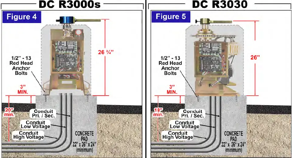
INSTALL ATION SPECIFICATIONS – CONCRETE PAD
WARNING
ALWAYS CONSULT AND FOLLOW ALL LOCAL BUILDING AND ELECTRICAL CODES PRIOR TO INSTALLATION.
CONCRETE PAD CONSTRUCTION
Dimensions given for the pad are based on soil bearing shear of 2000 P.S.F. These figures may have to be adjusted depending on local soil conditions.
- Construct form for mounting the pad according to dimensions shown in Figure 1, 2 & 3.
- Locate the mounting pad according to the dimensions given in illustration.
- Level the top edge of the form.
- Set reinforcing bars and wire mesh.
- Mix concrete, pour mixture into form. Level and finish surface after pouring is complete.
- Allow the pad to cure for 48 hours,and remove the forms.
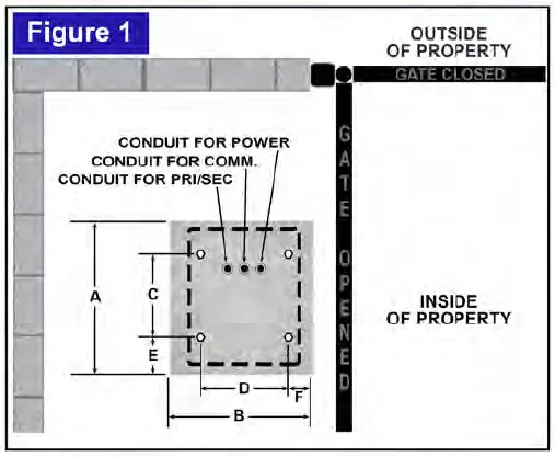
| MODEL | A | B | C | D | E | F |
| DC R3000s | 26″ | 20″ | 14″ | 13 1/2″ | 6″ | 21/2″ |
| DC R3030 | 26” | 20″ | 13″ | 13 112″ | 6” | 21/2″ |
FOOTPRINTS 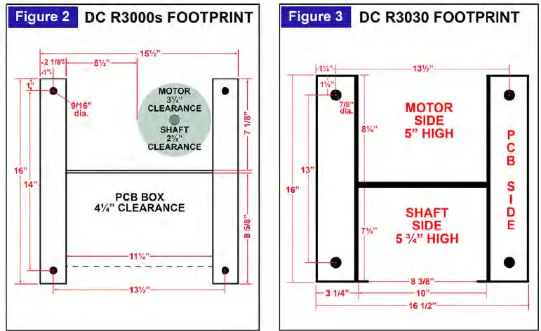
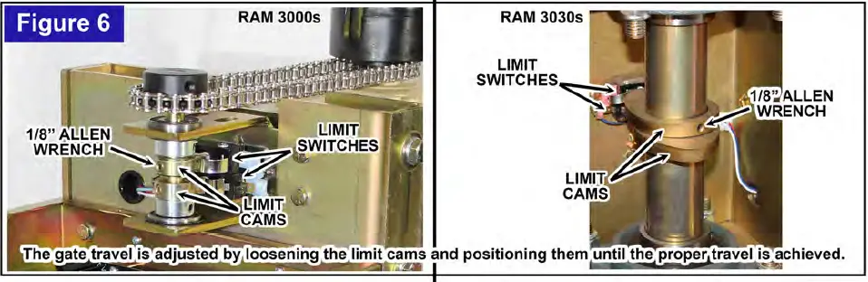
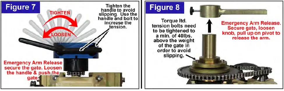
GATE TRAVEL ADJUSTMENT
EMERGENCY RELEASE & TORQUE LTD TENSION
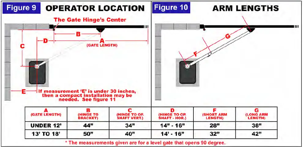
OPERATOR LOCATION & ARM LENGTHS
WARNING MAKE SURE THERE ARE NO PINCH POINTS CREATED WHEN THE ARMS ARE IN THE FULLY OPEN POSITION.
USE THE LENGTH OF THE FLAT BAR ON THE GATE BRACKET AND PIVOT TO ADJUST THE ARMS FOR PROPER LENGTHS BEFORE WELDING THEM.
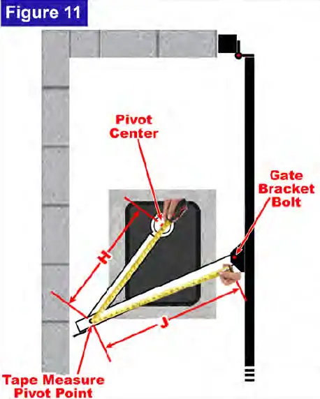
COMPACT & CUSTOM INSTALLATIONS
- Get a tape measure.
- Close the gate completely.
- Measure the distance from the pivot center to the gate bracket bolt. We will call this measurement ‘X’.
- Open and secure the gate.
- Bend the tape measure (see Figure 11) to create a pivot point.
- Place the end of the tape measure (O”) on the gate bracket bolt.
- Place measurement ‘X’ (from step 3) of the tape measure onto the pivot center.
- Move the pivot point of the tape measure until it is about 3 inches from the obstruction (wall).
- ‘H’ is the length of the short arm.
- ‘J’ is the length of the long arm.
LOOP LOCATION & INSTALLATION
WARNING LOOP SENSORS CANNOT BE USED TO MEET UL326 REQUIREMENTS. PHOTO EYES, EDGES OR THE EQUIVALENT ARE NEEDED TO MEET UL326 REQUIREMENTS.
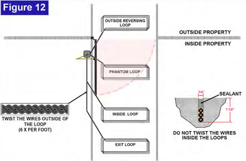
- REVERSING LOOPS: Hold the gate open or reverse a closing gate if a vehicle is detected.
- PHANTOM LOOP: Placed under the swing path of a swing gate. This loop will check before the gate closes to see if a vehicle is within the swing path, if a vehicle is within the swing path the gate will not move.
- INSIDE LOOP: Placed just outside of the swing path of the gate. Stops the gate from opening until it is cleared.
- EXIT LOOP: Opens and holds the gate open.
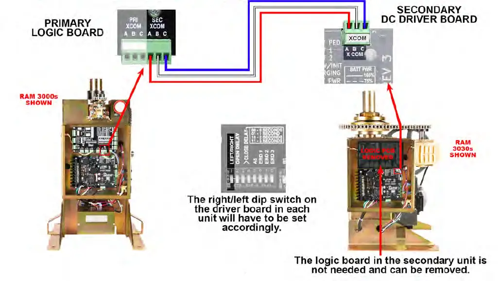
DUAL PARTING GATES – PRIMARY & SECONDARY
- Connect a 3-wire, shielded cable (not supplied), between ‘SEC XCOM’ on the logic board in the primary unit and ‘XCOM’ on the AC driver board in the secondary unit.
- The primary/secondary wires should be ran in a conduit separate from the power.
*IMPORTANT*
When connecting the primary/secondary cables, both operators must be turned off. Once the cables are connected, power can be reapplied.
ENTRAPMENT TYPES & PROTECTION MEANS
WARNING ALL ENTRAPMENT AREAS NEED TO BE PROTECTED BV A MONITORED ENTRAPMENT PROTECTION DEVICE.
- Every swing gate operator requires a minimum of:
- entrapment protection device in the opening direction, and
- entrapment protection devices in the closing direction.
- One in each direction is covered by the inherent ERO system (Type A).
Therefore, at least one additional photo eye, edge sensor or equivalent is required to be added, by the installer, in the closing direction. - Since every installation is different, it is up to a qualified, trained technician to make sure that ALL entrapment areas are protected by an entrapment protection device.
- It is also up to a qualified, trained technician to determine what types and how many devices are needed.
- A Maximum of 10 monitored entrapment devices may be connected to your operator, depending on direction of travel and type of device.
Horizontal Swing Entrapment protection types A, 81, 82, C or D
Note – The same type of device shall not be utilized for both entrapment protection means.
| Type A | Inherent entrapment protection system. |
| Type B1 | Non-contact sensor (photoelectric sensor or the equivalent). |
| Type B2 | Contact sensor (edge device or the equivalent). |
| TypeC | Inherent force limiting, inherent adjustable clutch or inherent pressure relief device. |
| Type D | Actuating device requiring continuous pressure to maintain opening or closing motion of the gate. |
| Minimum Quantity of Entrapment Protection Means | ||
| Opening | Closing | |
| Horizontal Swing Gate | 1* | 2* |
*The Inherent ERO System (Type A) counts as 1 entrapment protection device in each direction. Therefore, a minimum of one more exterior entrapment protection device (type 81 or 82) needs to be installed in the closing direction.
EMX – NIR-50-325 – PHOTO EYE WIRING DIAGRAM 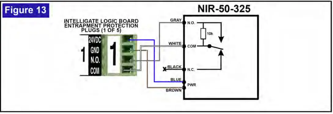
ENTRAPMENT PROTECTION AREA
WARNING MAKE SURE ALL ENTRAPMENT ZONES ARE PROTECTED BY APPROVED ENTRAPMENT PROTECTION DEVICES.
ENTRAPMENT ZONE: Locations between a moving gate and a counter-opposing edge or surface where entrapment is possible up to 6ft above grade. SUch locations occur if during any point in travel the gap between a moving gate and fixed counter opposing edges or surfaces are less than 16 inches
In order to prevent serious injury? bodily harm or death from a moving gate:
Entrapment protection devices must be installed to cover all entrapment danger areas and locations during a gates opening and closing cycles.
Since every installation is (different, if is up to a qualified and trained technician to determine:
- All possible Entrapment areas & locations
- The amount and type of entrapment protection devices that are needed.
Approved anti-entrapment devices {10K method):
- EMX NIR 50-325
- EMX IRB-MON
- EMX IRB-RET
- OMRON – E35-R1 0K4
- MILLER EDGE – PRIME GUARD
- MILLER EDGE – REFLECT-GUARD
- SECO-LARM – “ENFORCER” – E931-S50RRGQ
- SECO-LARM – “ENFORCER” – E936-S45RRGQ
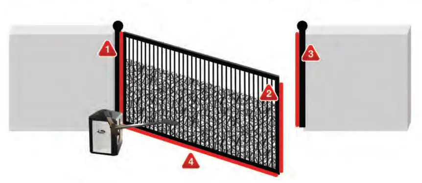
- HINGED POST AREA -PINCH POINT
- LEADING EDGE – ENTRAPMENT
- POST-ENTRAPMENT
- LOWER GATE EDGE – ENTRAPMENT
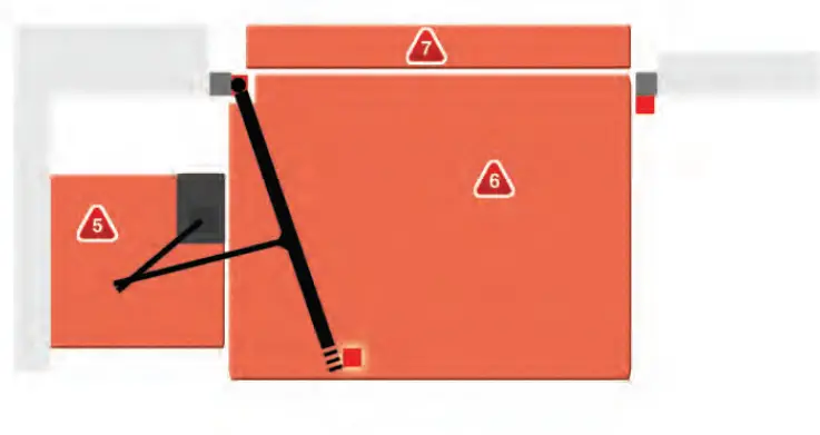
- BACK PLANEZONE-ENTRAPMENT
- INTERIOR ZONE – SAFETY
- EXTERIOR ZONE -SAFETY
LOGIC & DC DRIVER BOARD – L.E.D. LAYOUT
LOGIC BOARD 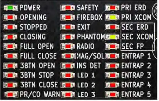
- POWER – Low voltage is present.
- OPENING – The gate is opening.
- STOPPED – The gate is stopped.
- CLOSING – The gate is closing.
- FULL OPEN – The open limit switch is being triggered.
- FULL CLOSED – The close limit switch is being triggered.
- 3BTN OPEN – 3-button station “open” button is being pressed.
- 3BTN STOP – 3-button station “stop” button is being pressed.
- 3BTN CLOSE – 3-button station “close” button is being pressed.
- PR/CO WARN – Pre-warn / Constant-warn relay is active.
- SAFETY – Safety I Reversing device is being triggered.
- FIREBOX – Firebox device is being triggered.
- EXIT – Exit device is being triggered.
- PHANTOM – Phantom device is being triggered.
- RADIO – Radio device is being triggered
- MAG/SOL – The magnetic I solenoid lock relay is active.
- INS DET – The inside detector is being triggered.
- LED 1 – Not used at this time.
- LED 2 – Not used at this time.
- LED 3 – Not used at this time.
- PRI ERO – ERO on the primary unit is being triggered.
- PRI XCOM – Communication on the primary unit is sending I receiving information.
- SEC ERO – ERO on the secondary unit is being triggered.
- SEC XCOM – Communication on the secondary unit is sending I receiving a signal
- SEC FP – The foot pedal switch on the secondary unit is being triggered.
- ENTRAP 1 – A monitored entrapment device on Entrapment #1 is being triggered.
- ENTRAP 2 – A monitored entrapment device on Entrapment #2 is being triggered.
- ENTRAP 3 – A monitored entrapment device on Entrapment #3 is being triggered.
- ENTRAP 4 – A monitored entrapment device on Entrapment #4 is being triggered.
- ENTRAP 5 – A monitored entrapment device on Entrapment #5 is being triggered.
DC DRIVER BOARD

- AC POWER – Low voltage is present.
- MOTOR 1 – Motor 1 is running.
- MOTOR 2 – Motor 2 is running.
- STOPPED – Gate is stopped.
- XCOM – Communication is sending I receiving information.
- KEY – Key input is being triggered.
- AUX 1 -1st auxiliary input.
- LED 1 – Not used at this time.
- ERO – ERO is being triggered.
- FOOT PEDAL – The foot pedal switch is being triggered.
- LIMIT 1 – Limit 1 limit switch is being triggered.
- LIMIT 2 – Limit 2 limit switch is being triggered.
- SLOW/INIT – Slow start & slow stop is being initialized.
- CHARGING – Battery is being charged.
- BATT PWR – Level of battery power.
- LED 2 – Not used at this time.
LOGIC BOARD DIP SWITCHES & PUSHBUTTONS

DIP SWITCH ‘A’
‘A’I, 2 & 3 -AUTOMATIC CLOSE TIMER
0 = *DOWN = UP
SWITCH 1 2 3 GATE OPEN DURATION
| 0 | 0 | 0 | DISABLED | |||
| 0 | 0 | 0 SECONDS | ||||
| 0 | 0 | 5 SECONDS | ||||
| 0 | 1 | 1 | 10 SECONDS | |||
| 1 | 0 | 0 | 15 SECONDS | |||
| 1 | 0 | 1 | 30 SECONDS | |||
| 0 | 45 SECONDS | |||||
| 60 SECONDS | ||||||
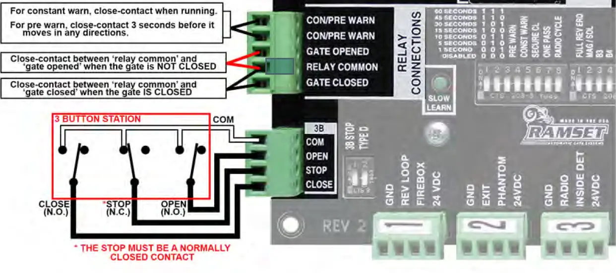
‘A’ 4 -PRE WARN ALARM
| DOWN | Normal Operation |
| UP | Triggers a closed contact between ‘CON/PRE WARN‘ outputs (located on relay connections plug) for 3 seconds before the gate moves In any direction. |
‘A’ 5 -CONSTANT WARN ALARM
| DOWN | Normal Operation |
| UP | Triggers a closedcontact between ‘CON/PRE
WARN‘ outputs (located on relay connections plug) whenever the motor is running. |
If both ‘A’ 4 & ‘A’ 5 are in the up position then there will be a closed contact on the con/pre warn outputs for 3 seconds before and as the motor is running.
‘A’ 6 -SECURE CLOSE
| DOWN | Normal Operation |
| UP | When power is lost and then regained, if all devices are clear & it’s safe, the gate will close |
‘A’ 7 -ONE PASS
| DOWN | Normal Operation |
| UP | While the gate is opening, if the rev loop Input is triggered and then cleared, the gate will immediately start closing. If the rev loop is then triggered again, before the gate is fully closed, the gate will stop and stay at rest until the rev loop input is cleared. Once the rev loop input is cleared, the gate will resume closing. At any
time if a valid open signal is received, the gate will open. |
‘A’ 8 – RADIO CYCLE
| DOWN | The gate will close, if It’s on the open limit. Otherwise, the gate will always open. |
| UP | The gate will close if it’s on the open limit. The gate will open if it’s on the close limit. If in travel, the gate will stop with the 1st command and reverse with a second command. |
DIP SWITCH ‘B’
‘B’ 1 -FULL REVERSE ERD
| DOWN | Normal Operation. If an obstruction is sensed, the gate will stop and reverse for 1 second. |
| up | If an obstruction is sensed:
Opening – Gate will stop and reverse for 1 sec. Closing – Gate will stop and reverse until fully open. |
‘B’ 2 -MAGNETIC/SOLENOID LOCK
| DOWN | Magnetic Lock • MAG/SOL relay is shorted when the gate is closed or closing. |
| UP | Solenoid Lock – MAG/SOL relay is shorted for 2 seconds when the gate starts to open. |
‘B’ 3 thru 8 – NOT USED AT THIS TIME
DIP SWITCH ‘C’
‘C’ 1 -3B STOP
| DOWN 3-button station- The ‘STOP’ input is active. A | |
| normally-closed contact switch must be present between ‘common’ and ‘stop’ | |
| UP | 3-button station- The ‘STOP’ input is bypassed. No connection between ‘common’ and ‘stop’ is needed. |
‘C’ 2 – TYPE D**
| DOWN | Type D device• is not being used to meet UL325 standards. |
| UP | Type D device• Is being used to meet UL325 standards. This disables all Inputs other than the 3-button station. Maintained signal required. |
Type D device -A pushbutton or equivalent that required a maintained pressure for activation .
For gale operators utilizing Type D protection:
- The gate operator controls must be placed so that the user has a full view of the gate area when the gate is moving,
- The placard as required by UL3.25 – 62.1.6 shall be placed adjacent to the controls.
- An automatic closing device (such as a timer, loop sensor, or similar device) shall not be employed, and
- No other activation device shall be connected.
PUSHBUTTONS
E.P. LEARN Monitored Entrapment Protection Learn Button
Activates the monitored entrapment protection learning process. This button is to be pressed after the entrapment protection devices are connected to the board. During this process, the LEDs will blink. The processor will check for devices connected. Once this process is complete, the LEDs will return to normal operation and the processor will monitor for the ‘learned’ devices connected. (For further information, see the Entrapment Protection section of this manual.)

SLOW LEARN
Sets gate travel for slow stop feature
Used during initial setup. After setting the limit switches, push and hold this button for 2 • 3 seconds. The gate will open to the open limit, stop, and then close to the closed limit. This sets up the gate travel, which in turn, allows the control board to know where the gate is at all times. 
ENTRAPMENT PROTECTION DIP SWITCHES & PLUGS

DIP SWITCH ‘D & E’
‘D’I, ‘D’2 & – *M.E.P.
‘0’ = ‘DOWN ‘1’=UP
SWITCH Dl D2 D3 GATE OPEN DURATION
| O | O | O | NO DEVICE CONNECTED | |
| 0 | 0 | 1 | NO DEVICE CONNECTED | |
| O | 1 | O | PHOTO EYE ON CLOSING | |
| o | 1 | 1 | EDGE ON CLOSING | |
| 1 | 0 | PHOTO EYE ON OPENING | ||
| 1 | 0 | 1 | EDGE ON OPENING | |
| 1 | 1 | o | PHOTO EYE ON OPENING & CLOSING | |
| 1 | 1 | 1 | EDGE ON OPENING & CLOSING |
‘D’4, ‘D’5 & ‘D’6 – *M.E.P.
0 = IDOWN 1’=UP
SWITCH D4 D5 D6 GATE OPEN DURATION
| O | O | O | NO DEVICE CONNECTED | |
| 0 | 0 | 1 | NO DEVICE CONNECTED | |
| O | 1 | O | PHOTO EYE ON CLOSING | |
| o | 1 | 1 | EDGE ON CLOSING | |
| 1 | 0 | 0 | PHOTO EYE ON OPENING | |
| 1 | 0 | 1 | EDGE ON OPENING | |
| 1 | 1 | O | PHOTO EYE ON OPENING & CLOSING | |
| 1 | 1 | 1 | EDGE ON OPENING & CLOSING |
‘D’7, ‘D’8 & ‘E’l – *M.E.P. #3
‘0’ = DOWN ‘1’= UP
SWITCH 07 D8 El GATE OPEN DURATION
| O | O | O | NO DEVICE CONNECTED | |
| O | O | 1 | NO DEVICE CONNECTED | |
| O | 1 | O | PHOTO EYE ON CLOSING | |
| 0 | 1 | 1 | EDGE ON CLOSING | |
| 1 | O | O | PHOTO EYE ON OPENING | |
| o | 1 | EDGE ON OPENING | ||
| 1 | 0 | PHOTO EYE ON OPENING & CLOSING | ||
| 1 | 1 | 1 | EDGE ON OPENING & CLOSING |
* M.E.P. = Monitored Entrapment Protection
‘E’2, ‘E’3 & ‘E’4 – *M.E.P. #4
‘0’ = IDOWN ‘1’=UP
SWITCH E2 E3 E4 GATE OPEN DURATION
| o | o | 1 | NO DEVICE CONNECTED | |
| 0 | 1 | O | PHOTO EYE ON CLOSING | |
| 0 | 1 | 1 | EDGE ON CLOSING | |
| O | O | PHOTO EYE ON OPENING | ||
| O | 1 | EDGE ON OPENING | ||
| 1 | 1 | O | PHOTO EYE ON OPENING & CLOSING | |
| 1 1 1 EDGE ON OPENING & CLOSING | ||||
‘E’5, ‘E’6 & ‘E’7 – *M.E.P. #5
0 = *DOWN 1=UP
SWITCH E5 E6 E7 GATE OPEN DURATION
| 0 | 0 | O | NO DEVICE CONNECTED | |
| 0 | 0 | 1 | NO DEVICE CONNECTED | |
| O | 1 | O | PHOTO EYE ON CLOSING | |
| o | 1 | 1 | EDGE ON CLOSING | |
| 1 | 0 | O | PHOTO EYE ON OPENING | |
| 1 | 0 | 1 | EDGE ON OPENING | |
| 1 | 1 | O | PHOTO EYE ON OPENING & CLOSING | |
| 1 | 1 | 1 | EDGE ON OPENING & CLOSING |

- OPEN – Used to protect during 2 the open cycle.
- CLOSE – Used to protect during the close cycle.
- PHOTO/EDGE – The type of device that is being connected.
- DOWN = photo-eye
- UP= edge connector
LOGIC BOARD PLUGS 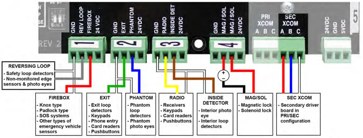
- REV LOOP • Used to stop the gate from closing. Holds the gate open when maintained. This is a non-monitored connection. Monitored devices should be connected to the entrapment protection plugs.
- FIREBOX• Used to open the gate for emergency vehicles. Requires a maintained signal. Overrides all safety devices.
- ONLY USE FOR EMERGENCY VEHICLES.
- EXIT • Used to open the gate and/or hold the gate open.
- PHANTOM • Used to hold the gate open when it’s on the open limit. Once the gate starts to close this has no effect. Works with a loop detector or photo eye to cover the area that the gate travels over.
- RADIO – Used to open, stop and close the gate. Full control.
- INSIDE DET – Stops a swing gate from hitting an obstruction when opening. When triggered, the gate will stop and wait until the detector is cleared. Once the detector is cleared, the gate will continue to open.
- MAG/SOL – Used with a magnetic lock or solenoid. See dip switch ’84’. This is a relay output. A separate transformer or power source is needed to work with this connection.
- MAG: The relay is closed when the gate is closing or closed.
- SOL: The relay is closed for 3 seconds as it begins to open, then releases.
- SEC XCOM • 3-wire conductor, preferably shielded, used to communicate between the primary and secondary units.

DC DRIVER BOARD DIP SWITCHES & PUSHBUTTONS
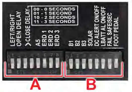
DIP SWITCH ‘A’
‘A’ 1 – LEFT 1 RIGHT
- DOWN Left hand installation
- UP Right hand installation
POINT OF VIEW – Standing on the same side of the gate the operator is installed on, looking through the gate opening. Operator on the Left = Left hand installation Operator on the Right = Right hand installation
‘A’ 2 – OPEN DELAY
- DOWN No delay on opening.
- UP 1 SECOND DELAY ON OPENING
‘A’ 3 & 4 – CLOSE DELAY
‘0’ = DOWN ‘I’=+UP
| 0 | 0 | NO DELAY ON CLOSING | |
| 0 | 1 | 1 SECOND DELAY ON CLOSING | |
| 1 | 0 | 2 SECOND DELAY ON CLOSING | |
| 3 SECOND DELAY ON CLOSING |
SWITCH 3 4 AMOUNT OF DELAY
A5 NOT USED IN THIS TIME
LEAVE IN DOWN POSITION
DIP SWITCH ‘B’
‘B’ 1 – ‘B’ 3 – NOT USED AT THIS TIME
‘B’ 4-SOLAR
| DOWN | Used on units where AC power is available and Batteries are usedfor backup only |
| UP | Used on units when no AC power is available and a solar panel is being used. |
‘B’ 5 – DC ALERT
| DOWN | OFF – Unit does not sound chirp when in DC mode (AC is not present) |
| UP | ON – A Chirp will sound whenever the unit is running in DC mode. (Running on Battery) |
‘B’ 6 – LBATT ALARM
| DOWN | OFF – When unit is shut down to low battery condition, no chirp will sound. |
| UP | ON – When unit is shut down to low battery condition, the unit will chirp. |
‘B’ 7 – FAIL SAFE/SECURE
| DOWN | OFF – FAIL SAFE – When entering into low battery mode, the gate will open and stay open. |
| UP | ON – FAIL SECURE – When entering into low battery mode, the safe will close. |
‘B’ 8 – FOOT PEDAL
| DOWN | OFF – Used on units that have a foot pedal. When the foot pedal is ‘down’ then no operation. |
| UP | ON – This switch should be up for all units that don’t have a foot pedal. |
PUSHBUTTONS

- OPEN – Opens the gate. When held down, in emergencies, it will override the monitored safety devices
- STOP – Stops the gate.
- CLOSE – Closes the gate. When held down, in emergencies, it will override the monitored safety devices.
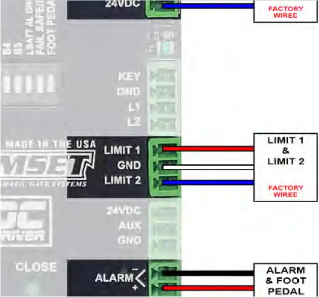
DC DRIVER BOARD PLUGS & FUNCTIONS
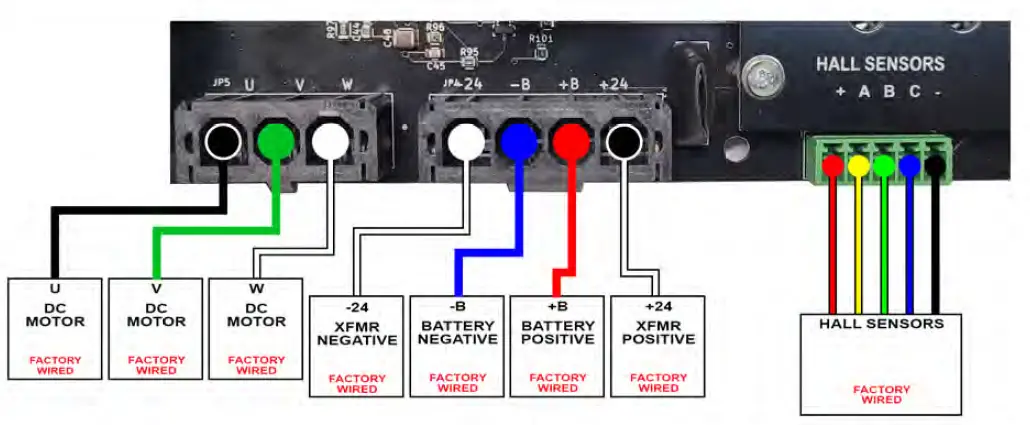
- U, V & W – DC MOTOR (Factory Wired) – Motor wires
- -24 XFMR NEGATIVE (Factory Wired) – Negative lead of transformer.
- -B BATTERY NEGATIVE (Factory Wired) – Negative lead of battery.
- +B BATTERY POSITIVE (Factory Wired) – Positive lead of battery.
- +24 XFMR POSITIVE (Factory Wired) – Positive lead of transformer.
- HALL SENSORS (Factory Wired) – 5-wire connection from the motor to the PCB. Allows board to know the position of the gate.
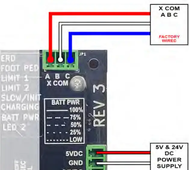
- X COM A, B & C (Factory Wired) – 3-wire communication between the logic board and the driver board.
- SV & 24V DC POWER SUPPLY (Factory wired) – 3-wire connection between the driver board and the logic board to power up the logic board.
- LIMIT 1 & LIMIT 2 (Factory Wired) – Wired to open and close limit switched. Stops the gate from moving in the appropriate direction.
- ALARM (Factory Wired) – UL alarm will sound after an obstruction has occurred twice in one gate travel.
- FOOT PEDAL (Factory Wired) – 2-wire connection to the foot pedal switch.

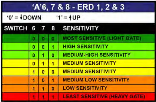
SPEED – The speed of the gate.
- 0 = 1′ per second
- 1 = 10″ per second
- 2 = 8″ per second
- 3 = 6″ per second
SLOW STOP – The gate will slow down before it is fully closed.
- 0 – 1 1 /2 seconds
- 1 – 2′ slow down
- 2 – 3′ slow down
- 3 – 5′ slow down

(M.E.P.) MONITORED ENTRAPMENT PROTECTION QUICK SETUP GUIDE
IMPORTANT: MAKE SURE THE M.E.P. DEVICE YOU ARE USING IS A UL.326 MONITORED ENTRAPMENT DEVICE USING THE 1 OK METHOD
- Slide Gate Requirements:
- Closing – Minimum 1 photo eye or edge sensor.
- Opening – Minimum 1 photo eye or edge sensor.
- Swing Gate Requirements:
- Closing – Minimum 1 photo eye or edge sensor.
- Opening – No minimum requirement.
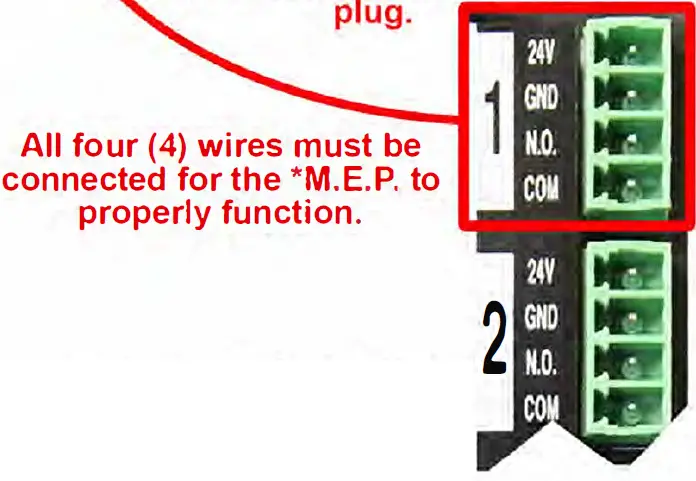
- M.E.P. #1
- Connect 4 wires (24V, GND, N.0. & COM) to the #1 plug (located on the right edge of the logic board # 1 thru #5)
- Set the corresponding dip switches
[MEP 1 = Dip switch section 1 (C1, C2, C3) … ] - if protecting the opening, turn the ‘OPEN’ dip switch on.
- if protecting the closing, turn the ‘CLOSE’ dip switch on.
- if using a photo eye, turn the ‘PHOTO/EDGE’ switch off.
- if using an edge sensor, turn the ‘PHOTO/EDGE’ switch on.
- M.E.P. #2 (if applicable)
- Connect 4 wires (24V, GND, N.O. & COM) to the #2 plug .(located on the right edge of the logic board# 1 thru #5)
- Set the corresponding dip switches
[MEP 2 = Dip switch section 2 (C4, CS, C6) … ] - if protecting the opening, turn the ‘OPEN’ dip switch on.
- if protecting the closing, turn the ‘CLOSE’ dip switch on.
- if using a photo eye, turn the ‘PHOTO/EDGE’ switch off.
- if using a edge sensor, turn the ‘PHOTO/EDGE’ switch on .
- Continue through M.E.P. #5 or until all MEP devices are connected.
- Once all M.E.P. devices are connected, push & hold the ‘EP LEARN’ button.
- When LEDs ‘ENTRAP 1’ through ‘ENTRAP 5’ start flashing, release the button.
- All 5 LEDs will go off for about 3 seconds.
- All 5 LEDs will blink 3 times.
- The corresponding LEDs with the MEPs that were connected will turn solid for 3 seconds. (Make sure the number of LEDs match the number of MEPs connected. If the numbers don’t match, check the wiring connection and repeat step 6.
Bill of Materials [RAM 3000, RAM 3100, RAM 30-30 DC]
Qty of Part Per Operator
| Part No. Part Description RAM 3000 DC RAM 3100 DC | RAM 30-30 DC | |||
| 800-00-85 | Chassis, [R3000s] | 1 | 1 | |
| 800-00-86 | Chassis, R30-30 ACDC | 1 | ||
| 800-02-07 | Gear Reducer – Size 70, Ratio 30:1 [R3000S] | 1 | 1 | |
| 800-02-08 | Gear Reducer – Size 70, Ratio 60:1 [R3030S] | 1 | ||
| 800-02-13 | Gear Reducer – Size 43, Ratio 30:1 [R3000S] | 1 | 1 | |
| 800-04-05 | Motor, Dc 3.3 Nm 24 Vdc 1500 Rpm | 1 | 1 | 1 |
| 800-06-00 | Sprocket – 50Bs15H X 1 1/8″ [R3030S] | 1 | ||
| 800-06-05 | Sprocket – 40Bs21 X 1′ [R5000S,R3000ACDC] | 1 | ||
| 800-06-07 | Sprocket – 40BS21 x 7/8″ [R3000s] | 1 | ||
| 800-08-06 | Pulley, Cast Iron – Ak104H [R3030S] | 1 | ||
| 800-08-45 | Pulley, Cast Iron – 5/8′ X 2′ – Ak20 [R300,R3000S,R3030S] | 1 | ||
| 800-10-42 | Belt, – 4L – 390 | 1 | ||
| 800-12-07 | Shaft, Output – 2 1/8″ X 21″ [R3030S] | 1 | ||
| 800-20-03 | Limit Switch [R3030S] | 2 | ||
| 800-20-05 | Limit Switch [R50,R30,R300,R302,R3000S] | 2 | 2 | |
| 800-28-25 | Pivot, Ram 3000/3100 | 1 | 1 | |
| 800-28-45 | Pivot Arm Release | 1 | ||
| 800-44-02 | Bearing Flange, Ucf211-35 [R3030S] | 2 | ||
| 800-46-11 | Bushing, Pulley Taper Hx-7/8 | 1 | ||
| 800-48-03 | Cam Limit Switch 3 1/16″ X 4″ : Id 2 3/16″ [R3030S] | 2 | ||
| 800-52-12 | Chain Drive, 34 Links, Size 50 | 1 | ||
| 800-52-23 | Chain #40 (23 Links) | 1 | 1 | |
| 800-52-24 | Chain, Limit Switch #35 (35 Links) | 1 | 1 | |
| 800-54-49 | Limit,Mounting Brack, C- Type | 1 | 1 | |
| 800-54-52 | Limit Switch Bracket [R300, R30-30 Acdc] | 1 | ||
| 800-56-11 | PCB Box [R302,300,R3000, R30-30, R5700] | 1 | 1 | 1 |
| 800-60-07 | Transformer, Dual 115V / 230V Input With 4 Input Leads | 1 | 2 | 2 |
| 800-60-10 | Switch, Rocker | 2 | 2 | 2 |
| 800-60-21 | Outlet, Single Square [R302] | 1 | 1 | 1 |
| 800-60-35 | Bridge Rectifier, Single Phase, 100 V, 35 A, Module, 4 Pins, | 1 | 2 | 2 |
| 800-65-01 | Control Board, Logic [AC/DC] | 1 | 1 | 1 |
| 800-65-04 | Control Board, Driver [DC] | 1 | 1 | 1 |
| 800-66-12 | Lexan, Plastic Cover [R302, R3000,R5700,R30-30 DC] | 1 | 1 | 1 |
| 800-70-00 | DC Battery, 12Vdc – 7.5Ah [Bbs] | 2 | 2 | 2 |
| 800-70-22 | Horn Alarm Buzzer 120 Db | 1 | 1 | 1 |
| 800-70-25 | Limit Switch Cam Assembly (Hub And Rollpin) | 1 | 1 | |
| 800-70-35 | Knob – 5/16″ – 18 X 1 1/2″ | 2 | ||
| 800-70-36 | Knob – 5/16″ – 18 X 1/2″ | 1 | ||
| 800-70-98 | Warning Sign For Gates – Slide/Swing | 2 | 2 | 2 |
| 800-75-04 | Access Door Assembly | 1 | 1 | |
| 800-75-14 | Cover Assembly [R30-30] | 1 | ||
| 800-75-17 | Cover Assembly- R3000,R3100 | 1 | 1 | |
Part No. represents ONE assembly although some models may contain two or more of each assembly
Assemblies [R3000, R3100, R30-30]
RAM 3000 RAM 3100 RAM 30-30
| 800-75-00 Arm Assembly [300,302,3000s] 1 1 | ||||
| 800-28-00 | Arm, Metal Tubing – 1″ X 2″ X 32″ – | 1 | 1 | |
| 800-28-01 | Arm, Metal Tubing – 1″ X 2″ X 42″ – | 1 | 1 | |
| 800-36-53 | Bolt, Hex Head – 5/8″ – 11 X 4 | 1 | 1 | |
| 800-38-78 | Nut, Hex Head Nylock – 5/8″ | 1 | 1 | |
| 800-40-40 | Washer, Flat – Id 5/8″ : Od 1 5/16″ | 3 | 3 | |
| 800-40-27 | Washer, Flat – Id 1/2″ : Od 1″ – F436 | 4 | 4 | |
| 800-36-34 | Bolt, Hex Head – 1/2″ – 13 X 2″ | 1 | 1 | |
| 800-38-76 | Nut, Hex Head Nylock – 1/2″ | 1 | 1 | |
| 800-28-30 | Plastic End Cap – 1′ X 2′ | 2 | 2 | |
| 800-54-37 | Bracket, Internal Gate 2020 | 1 | 1 | |
| 800-54-10 | Bracket, External Channel | 1 | 1 | |
| 800-28-30 | Plastic End Cap – 1′ X 2′ | 2 | 2 | |
| RAM 3000 | RAM 3100 | RAM 30-30 | ||
| 800-75-03-L | LEFT-Heavty Duty Arm Assembly [30-30] | 1 | ||
| 800-75-03-R | RIGHT-Heavty Duty Arm Assembly [30-30] | 1 | ||
| RAM 3000 | RAM 3100 | RAM 30-30 | ||
RAM 3000 RAM 3100 RAM 30-30
| 800-75-42 Torque Limited Assym [30-30 DC] 2 | ||||
| 800-06-10 | Sprocket – 50B54 [R3030S] | 1 | ||
| 800-26-02 | Friction Disc, Torque Limited – Id 4 1/4″ : Od 7″ [R3030S] | 2 | ||
| 800-26-11 | Tension Washer, Torque Limited – Id 3 7/8″ : Od 6″ [R3030S] | 1 | ||
| 800-34-70 | Set Screw – 1/2″ – 13 X 1/2″ | 2 | ||
| 800-36-22 | Bolt, Hex Head – 3/8″ – 16 X 1 1/4″ | 3 | ||
| 800-42-42 | Key Way – 1/2″ Sq. X 8″ | 1 | ||
| 800-46-12 | Bushing, Metal – I.D. 3 13/16” – O.D. 4 3/16” [R3030] | 1 | ||
| 800-58-01 | Arbor Nut, Torque Limited [R3030S] | 1 | ||
| 800-58-12 | Arbor Washer, Torque Limited [R3030S] | 2 | ||
| 800-58-32 | Arbor, Torque Limited [R3030S] | 1 | ||
RAM 3000 RAM 3100 RAM 30-30
| 800-75-50 Clamp Release Assembly [R302,R3000] 1 1 | ||||
| 800-28-35 | Release, Lever Handle – 5/8″ – 11 X 1 7/8″ Thread [R3000S] | 1 | 1 | |
| 800-38-18 | Nut, Hex Head – 5/8″ | 1 | 1 | |
| 800-40-40 | Washer, Flat – Id 5/8′ : Od 1 5/16′ | 2 | 2 | |
| 800-36-55 | Bolt, Hex Head – 5/8″ – 11 X 2″ | 1 | 1 | |
| 800-48-80 | Clamp – Back [R3000S] | 1 | 1 | |
| 800-48-81 | Clamp – Front [R3000S] | 1 | 1 | |
| 800-54-20 | Bracket, Clamp Arm [R302 R3000S] | 1 | 1 | |
| 800-36-30 | Bolt, Hex Head – 1/2″ – 13 X 1″ | 2 | 2 | |
| 800-40-76 | Washer, Split Lock – 1/2″ | 2 | 2 | |
RAM 3000 RAM 3100 RAM 30-30
| 800-76-04 Limit Shaft Assembly [R3000,R3100] 1 1 | ||||
| 800-12-11 | Shaft, Limit Switch-1/2 X 4 1/4 [R3000AC/DC] | 1 | 1 | |
| 800-06-02 | Sprocket – 35Bs17 X 1/2″ (2 1/4″ Od – No Keyway) [R5000S,R3000S] | 1 | 1 | |
| 800-44-04 | Bearing, Sealed – 1621-2Rs-Nr X 1/2″ W/Snap Ring [R100,R5000S,R3000S] | 2 | 2 | |
| 800-70-10 | Collar, Limit Shaft – 1/2″ | 2 | 2 | |
| 800-48-02 | Cam, Limit – Steel – 1/2″ [R3000S] | 2 | 2 | |
- RAMSET AUTOMATIC GATE SYSTEMS, INC.
- 9116 DE GARMO AVE
- SUN VALLEY, CA 91352
- 800-771-7055
Documents / Resources
 |
RAMSET AUTOMATIC GATE SYSTEM RAM3100DC-PE High Traffic Swinging Gate Operators [pdf] Instruction Manual RAM3100DC-PE High Traffic Swinging Gate Operators, RAM3100DC-PE, High Traffic Swinging Gate Operators, Traffic Swinging Gate Operators, Swinging Gate Operators, Gate Operators, Operators |


