Process Solutions Automation Control PSC6194 Controller Readout and Control System


Product Overview
To control the liquid and gas supply flows, Process Solutions Corp. offers a custom engineered solution consisting of a 4.3” color touchscreen PLC readout and control system. The touchscreen enables the user to easily view or change functions. The PSC6194 controller serves as a power supply unit, for up to two meters and two controllers, and comes equipped with Analog IOs and Modbus interface. The controller also provides data logging of instrument data.
Display

The controller consists of the following:
- 4.3” color touchscreen PLC
- Flow Controller – Remote control analog IO connection (Ch. 1 & 2)
- Flow Meter – Remote control analog IO connection (Ch. 3 & 4)
- RS-485/Power (+) –communicates and powers meters/controllers via Modbus
- Ethernet Lan1
- Program PLC
- Additional communication port
- Power Port –
- 120 Vac wall plug connection
- Plug must be disconnected to Power Off
Connections

Powering Up

Model Key
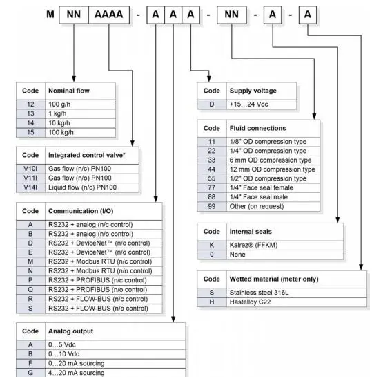
The model key on the product label contains information about the technical properties of the instrument as ordered. The specific properties can be retrieved with the diagram below (Mini-Cori controller example).
Refer to the Communication (I/O) to determine if the Broncho’s instrument is equipped with Modbus communication.
Analog Setup
Connecting Bronkhorst flow instruments to PSC controller via RS232, Channel 1 – 4. Bronkhorst instruments must be configured in Analog Mode to communicate via RS232.
Modbus Setup
Connecting Bronkhorst flow instruments to PSC controller via RS485/Power. Bronkhorst instruments must be configured in Modbus Mode to communicate.
| Communication settings are: | |
| Baud rate: 38400 Parity: Even Data Bit: 8 Stop Bit: 1 |
MFC#1: Address 1 MFC#2: Address 2 MFM#1: Address 3 MFM#2: Address 4 |

Configure Control Mode
To change Bronkhorst instrument from Analog to Modbus, or vice versa, the control mode must be configured via FlowDDE
(https://www.bronkhorst.com/en-us/products-en/accessories-and-software/flowware/flowdde/).
Connecting to FlowDDE
In the messages section the general procedure to start serving client applications with the FlowDDE server is described in four steps:
- Connect an instrument to a COM port of the PC
- Set the communication settings
- Start the communication
- Press F3 or
- Communication tab > Open Communication
- Wait until FlowDDE is ready
- Message: “Server is active and ready for any client”
If further instruction is needed, please refer to the FlowDDE Manual found in the link above.
Analog to Modbus Configuration
After opening communication, use the following steps to change the Control Mode from Analog operation to Modbus operation:
- FLOW-BUS tab > Test Flow-BUS and DDE
- Or Press F6
- Select the following parameters to view simultaneously
- Parameter 7 – InitReset
- Parameter 12 – IO Status
- Set parameter InitReset to 64 (unlocked)
- Read parameter IO Status
- Subtract 64 from the read value
- New Parameter Value: 15 or 11
- Write the new value to parameter IO Status
- Set parameter InitReset to 82 (locked)
- Restart Bronkhorst instrument
- InitReset must be unlocked/locked for the new Control Mode to remain after the instrument is restarted
Modbus to Analog Configuration
After opening communication, use the following steps to change the Control Mode from Modbus operation to Analog operation:
- FLOW-BUS tab > Test Flow-BUS and DDE
- Or Press F6
- Select the following parameters to view simultaneously
- Parameter 7 – InitReset
- Parameter 12 – IO Status
- Set parameter InitReset to 64 (unlocked)
- Read parameter IO Status
- Add 64 from the read value
- New Parameter Value: 79
- Write the new value to parameter IO Status
- Set parameter InitReset to 82 (locked)
- Restart Bronkhorst instrument
- InitReset must be unlocked/locked for the new Control Mode to remain after the instrument is restarted
Basic Operation
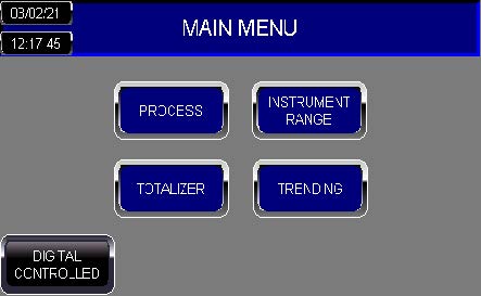
Main Menu
The display consists of the following readout areas:
- Process – readouts and set points Bronkhorst meter/controllers
- Instrument Range – set full range according to instrument
- Trending – Flow vs. Time plots for each instrument
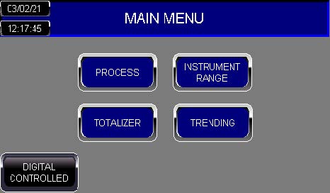
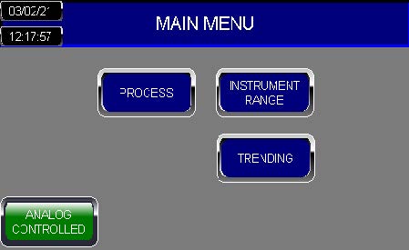
- Communication Mode – Analog Controlled or Digital Controlled
- Date and Time Settings
- Totalizer* – Only available via Modbus (Digital Controlled) and Coriolis Instrument
| User Interface | |
| Analog Controlled
Digital Controlled |
Communication Mode The PSC6194 controller is equipped with two forms of communication: Analog Controlled – Analog IOs, 4 – 20 mAsignalDigital Controlled – Modbus communication Modbus features:
Both Communication Modes support up to four instruments, 2 Mass Flow Controllers and 2 Mass Flow Meters. |
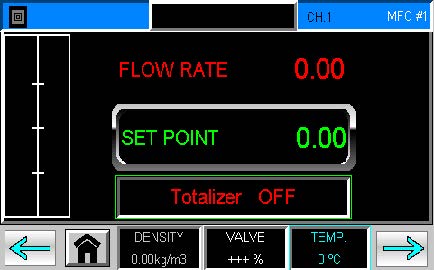
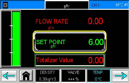
| Process Screen
|
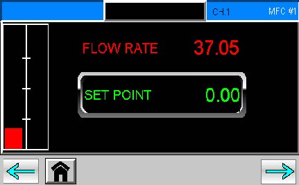
Process Screens The Process Screens will display the flow rates, set points and other process conditions for the Bronkhorst instruments.The Process screens consist of: Instrument Label: (Blue Label) Displays channel and instrument number on the top right corner. Units: (Black Label) To configure the instrument’s units (i.e. g/hr) |
Process Screen
Keyboard |
Labeling Units To edit the Instruments’ Units, press the black label, as shown by the X on the image, for the keyboard to appear. (i.e. g/hr, kg/hr, etc.)Use the touchscreen to name the instrument and press ENTER.ENTER – Save value and return to previous screen. ESC – Return to previous screen without saving. |


Process Screen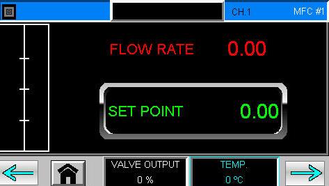
Set Point Warning |
Edit Set Points
To edit the set point of the instruments, press the boxed number, as shown by the X on the image, for the numerical pad to appear. Set the value and press ENTER. No Border – Valid Set Point Yellow Border – the Set Point is set above the Instrument Range. Red Border – the Set Point is locked due to the Totalizer. Please see Totalizer settings for details.
ENTER – Save value and return to previous screen. The value must be within the Instrument’s range, or the Status light will start blinking with an error. |
Instrument Range Screen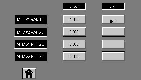
Numerical Keypad
|
Instrument Range The Instrument ranges must be set to the FULL flow range of the Bronkhorst instrument, shown on instrument label. To edit range, press on the corresponding SPAN value, as shown by the X on the image, for the Numeric Keyboard.
|
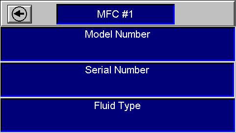
Process Screen
Details Screen |
View Details To view the instrument details, press the BLUE label, as shown by the X on the image. The next screen displays the following instrument details:
Press the Arrow button on the Details Screen to return to the previous screen. |
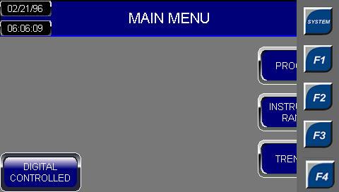
Process Screen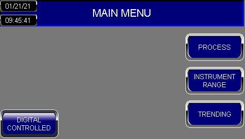
Function Buttons |
System Menu To access the System Menu, press the top right corner, as shown by the X on the image, for the Functions Buttons to appear.Select the SYSTEM button to view the System Menu. ESC – Return to previous screen without saving. |

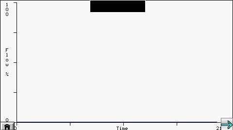
| Trending Screen
|
Trending The Trending screens compare the Flow vs. Time values for each instrument. The Instruments’ Units are displayed on the black label. ARROWS – navigate between screen HOME – Return to Main Screen |
| Totalizer | |
Main Screen Process Screen Process Screen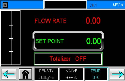 |
Accessing Totalizer The Totalizer is only available via Modbus for Coriolis Instruments. The Totalizer may be accessed from the Main Screen or the Mass Flow Controllers’ Process Screens, MFC# 1 and 2, as shown by the X. |
Totalizer Screen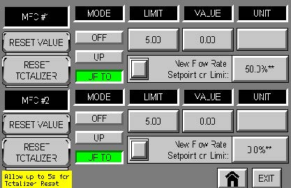 |
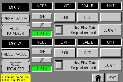
Totalizer Screen The Totalizer Screen displays two separate Totalizers for both MFC# 1 and 2. Each Totalizer contains the following settings:Mode – Mode of the corresponding Totalizer Limit – Totalizer limit/batch size in units selected with parameter Unit. Value – Current totalizer value in units selected with Unit. Unit – This parameter contains the name of the totalizer readout unit. Setpoint Mode – Specifies whether or not to change the setpoint after reaching the totalizer limit. New Setpoint(%) – New (safe) setpoint when a totalizer limit is reached until Totalizer Reset. Reset Value – Resets totalizer value only. Reset Totalizer – Resets totalizer value and new setpoint setting. |
OFF Mode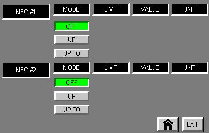
Up Mode Up To Mode |
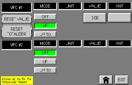
Totalizer Modes The Mode of the corresponding Totalizer can be selected and changed from the Totalizer Screen.The avaliable modes are:OFF – Totalizer off (default) UP – Counting up continuously UP TO – Counting up until limit is reached (set by Totalizer Limit) Each Mode will display different settings: OFF –
UP –
UP TO –
|
Configure Units
Units Page
|
Totalizer Unit To configure the totalizer units, press the box below the Unit label, as shown by the X, to navigate to the corresponding Units Page.Once at the Unit Page, press the desired Unit once and allow up to 5 seconds to update. The configured unit will be displayed at the bottom left corner.The Units available to configure from will depend on the Instrument Mode. Instrument Mode must be configured by FlowDDE.Instrument Modes: Mass Flow, Normal Volume Flow, Standard Volume Flow, Volume Flow (Actual) Totalizer Unit supports the following values: Volume Flow – l, mm3, ml, cm3, ul, m3 Normal/Standard Volume Flow – ln, mm3n, mln, cm3n, uln, dm3n, m3n, ls, mm3s, mls, cm3s, uls, dm3s, m3s Mass Flow – g, mg, ug, kg EXIT – Return to previous screen without saving. HOME – Return to Main Screen |
Configure Limit |
Totalizer Limit The Totalizer Limit is displayed in units selected with parameter Unit. To edit the Totalizer Limit, press the number box below the Limit Label, as shown by the X. Red Border – when Value reaches Limit. ENTER – Save value and return to previous screen. ESC – Return to previous screen without saving. |
Configure New Setpoint Mode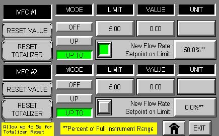 |
New Setpoint Mode To configure the New Setpoint Mode, press the checkbox to activate setting, as shown by the X.Grey – No setpoint change. Green – Active; Change setpoint to New Setpoint. |
Configure New Setpoint |
New Setpoint To configure a New Setpoint when limit is reached, press the percentage value, as shown by the X. Red Border – when value reaches limit, the new setpoint is locked until Totalizer Reset is executed. New Setpoint is the percent value of the FULL Instrument range.Examples: New Setpoint at 0%: Full Instrument Range: 500 grams/hr Setpoint: 400 grams/hrWhen limit is reached, New setpoint value: 0 grams/hr New Setpoint at 50%: Full Instrument Range: 500 grams/hr Setpoint: 400 grams/hr When limit is reached, IMPORTANT: |
Reset Value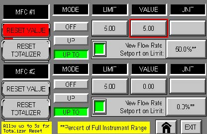 |
Reset Value To reset Value only, press and hold the Reset Value button for 1s, as shown by the X. Value will reset immediately. |
Reset Totalizer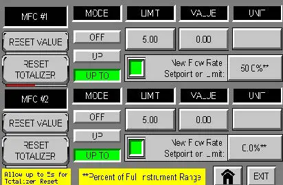
|
Reset Totalizer To reset the Value and Setpoint, press and hold the Reset Totalizer button for 1s, as shown by the X. Allow up to 5 seconds for the Totalizer to Reset. |

PROCESS SOLUTIONS CORP.
(281)-491-3833
SALES@PSCTEXAS.COM
Documents / Resources
 |
Process Solutions Automation Control PSC6194 Controller Readout and Control System [pdf] User Guide PSC6194 Controller Readout and Control System, PSC6194, Controller Readout and Control System, Readout and Control System, Control System |


