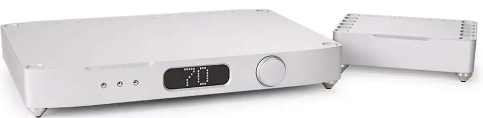
MSB TECHNOLOGY The Discrete DAC interface Network Renderer V2 Streaming Decoding
Product Specifications
- Product Name: Discrete DAC
- Manufacturer: MSB Technology
- Interface: Analog and Digital
- Power Supply: Dual-link power adapter
- Compatible with: Premier Powerbase (Upgrade)
Discrete DAC Support Page
All Discrete DAC support topics, as well as a full PDF version of this user guide, can be found online by visiting the URL listed below or by scanning the following QR Code.

https://www.msbtechnology.com/dacs/discrete-dac-support/
Discrete Series Youtube Playlist
Any Discrete DAC support videos, as well as other related product videos, can be found online by visiting the URL listed below or by scanning the following QR Code.

This user guide is modeled after the following firmware revisions: The Discrete DAC: 22.14
The Premier Digital Director: 11.11
Setup and Quick Start
The Discrete DAC interface is simple with few user controls. The input source defaults to auto switching and the display will let you know if you have an active input. Make the necessary connections, power on your system and turn the volume knob up until you hear music.
Step 1.
Unbox the unit(s) and place the unit(s) into their desired locations in your audio system.
Step 2.
If using the Discrete Supply, you’ll have one Dual-link cable and one Dual-link power adapter. Plug the adapter into the back of the Discrete DAC and then connect the Dual-link power cable into both the DAC and Discrete Supply.
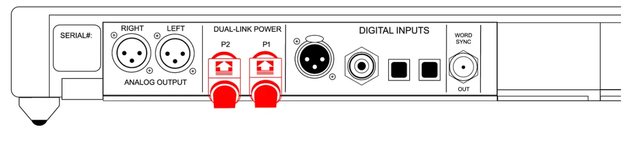
Premier Powerbase Connections (Upgrade)
If using a Premier Powerbase, you’ll have two Dual-link cables. Use both cables to connect each of the power connectors located on the Premier Powerbase to both of the power connectors located on the back of the Discrete DAC.
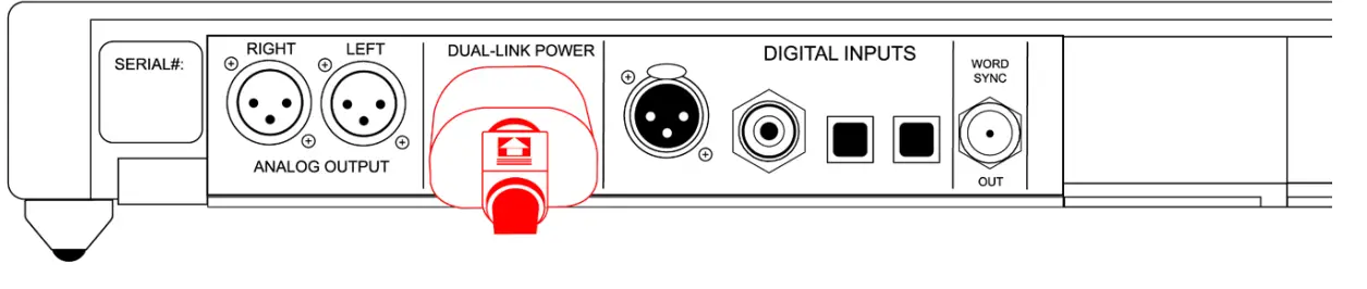
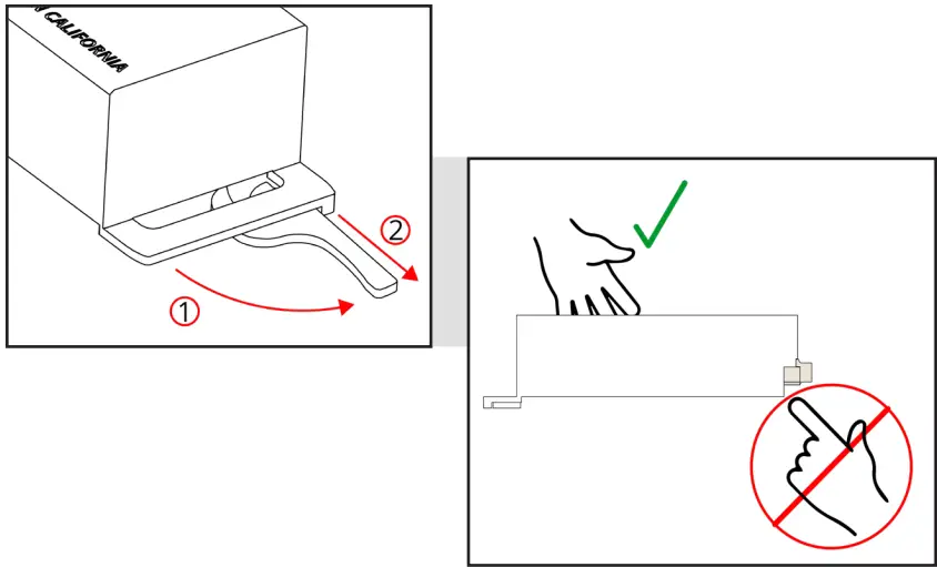
How to Disconnect Dual-link Cables
To disconnect a Dual-link cable, simply pinch the portion of the cable where the flat portion and arrow symbol are located and pull the shoulder of the cable directly back from the jackpanel. No twisting or rotating is required to disconnect the cable.
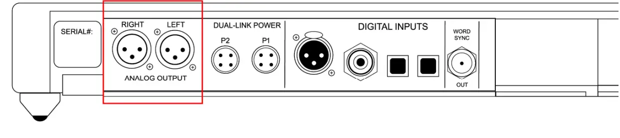
Step 3.
Connect the Analog outputs of your Discrete DAC to the power amplifier(s) in your audio system.
Step 4.
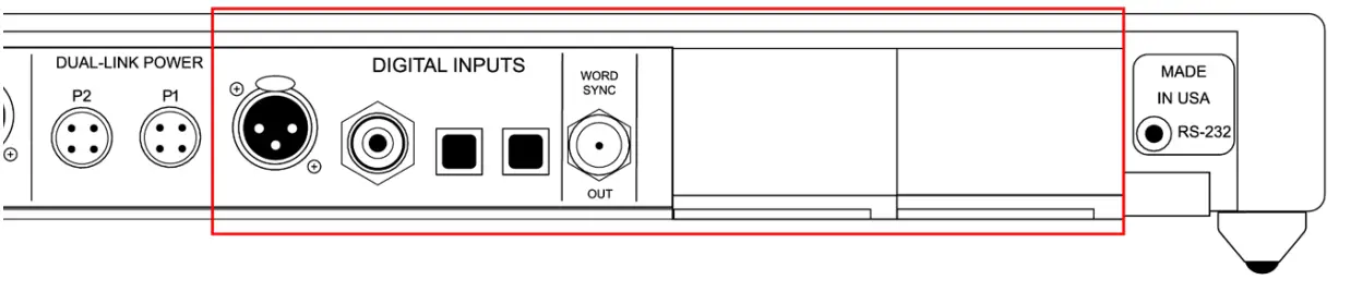
Connect all of your desired digital audio sources to the matching digital inputs on your Discrete DAC. The DAC will automatically switch to any active digital input source. The Frequency of the incoming digital source will be displayed on the unit when a source has been switched to.
Step 5.
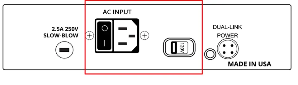
Ensure that the correct mains voltage for your country is selected on the back of the Discrete Supply and then connect the power supply using the supplied IEC cable. If using the Premier Powerbase, the unit will automatically switch to the required mains voltage.
Step 5.
Ensure that the correct mains voltage for your country is selected on the back of the Discrete Supply and then connect the power supply using the supplied IEC cable. If using the Premier Powerbase, the unit will automatically switch to the required mains voltage.
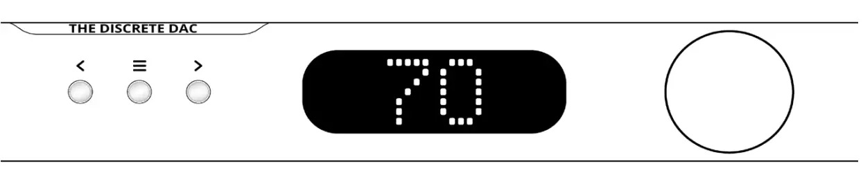
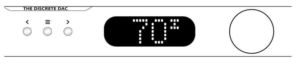
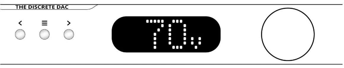
DAC User Interface
Menu Button |
The Menu button is single purpose: it will enter the setup menu at the top of the menu tree. If in the setup menu (it doesn’t matter where), this button will exit the setup menu and return to the normal audio listening function. |
Arrow Buttons |
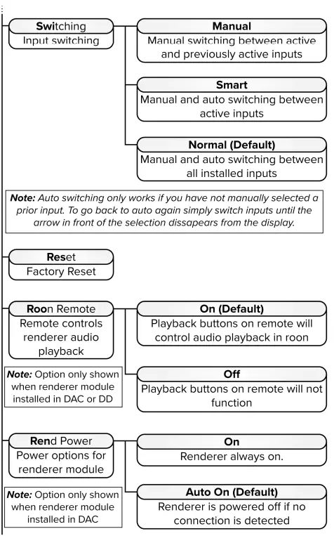
The right and left arrows switch inputs. The ‘Auto’ mode will be in the list of inputs. If ‘Auto’ is selected, the unit will automatically switch inputs based on priority (Input slot D being the highest priority and slot A being the lowest priority). When a source with a higher priority becomes active, the unit will automatically switch to the new, higher priority input. Toggling through the inputs manually will defeat any auto switching. When in the setup menu, the arrows move right and left through the menu structure. |
| Volume Knob | This knob adjusts the volume between 0 and 106. |
| Display | The display shows the Input, bit-depth, sample rate, or volume. |
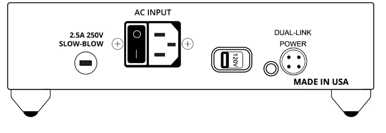
 Discrete Supply (Standard)
The Discrete DAC comes standard with an easy-to-use dedicated power supply. There is a voltage switch located on the back of the unit to select between 120V and 220V mains voltage. There is also a power switch located next to the IEC connector for turning on or shutting off your unit. One fuse can be found on the back of the unit. – 2.5A 250V Slow blow fuse.
Premier Powerbase (Upgrade)
The powerbase contains isolation technology. The powerbase detects the input voltage and switches to 120 volt or 240 volt operation. It’s also available in a fixed 100 volt configuration. This powerbase has over-voltage protection.
Two fuses are provided:
- 5A 250V Slow blow – 5 mm x 20 mm miniature fuse
- 100mA 250V Slow blow – 5 mm x 20 mm miniature fuse (Internal standby supply only).
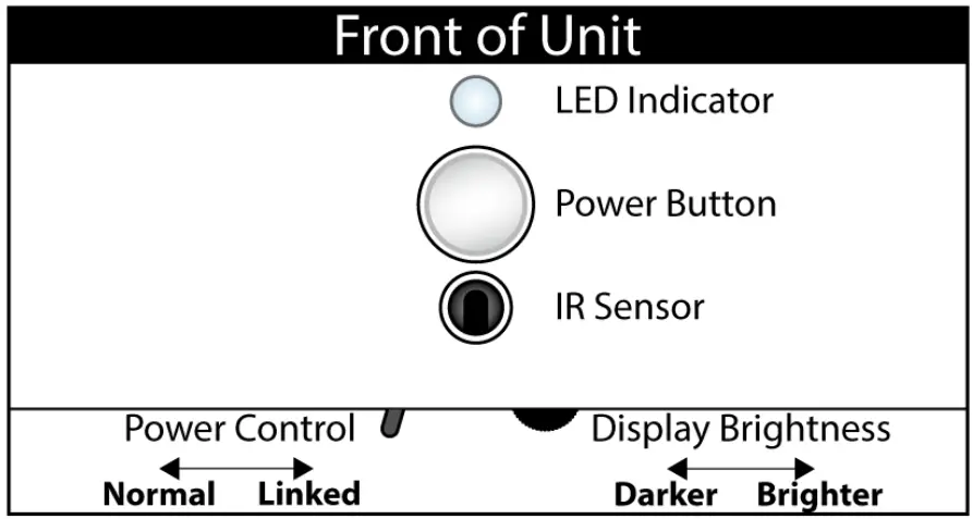
Premier Powerbase User Interface
There is one button on the front of the powerbase— as well as two control features just under the front of the powerbase, on the bottom.
| LED indications | White – Power On
Red – Power off White/Red – Unit is in “Normal” mode, but the 12v trigger has turned it off. Flashing Red – The unit is over voltaged or has over heated and has gone into protection. (Once the problem has been resolved, be sure to cycle the unit’s power.) |
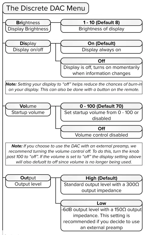
| Display brightness | This is a spinning wheel to control the brightness for the power indicator light. |
| Power control | Normal – This sets the powerbase as the 12 volt trigger master.
Linked – This sets the powerbase as the 12 volt trigger slave. The ‘Normal’ powerbase will control this unit. |
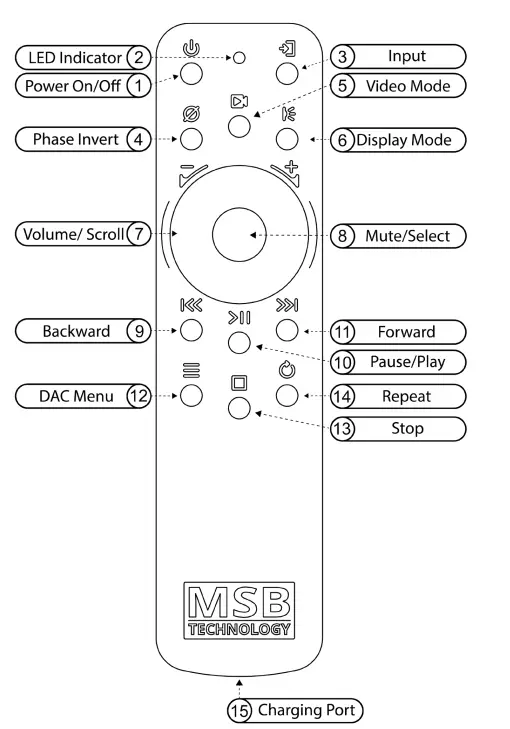
The MSB Remote
| 1 | Power On/Off | Powerbase on and off. When the powerbase is linked to an amplifier or MSB product via the 12 volt trigger system, this button will turn off the entire system. |
| 2 | Indicator LED |
|
| 3 | Input | Toggles directly through DAC inputs |
| 4 | Phase Invert | Toggles phase invert (Ø – on display) |
| 5 | Video Mode | Toggles video mode (“Video” – on display) |
| 6 | Display Mode | Toggles between the three display modes. |
| 7 | Volume/Scroll | The center scroll wheel controls DAC volume and scrolls when in the menu. |
| 8 | Mute/Select | DAC mute and select when in the menu. |
| 9 | Backward | Skip backward (Renderer and MSB Transport only) |
| 10 | Play/Pause | Play and pause (Renderer and MSB Transport only) |
| 11 | Forward | Skip forward (Renderer and MSB Transport only) |
| 12 | DAC Menu | Enter DAC menu
While in menu: Up – Volume wheel up Down – Volume wheel down Enter – Mute (Center button) Return – DAC menu button |
| 13 | Stop | Stop media (Renderer and MSB Transport only) |
| 14 | Repeat | Track or playlist repeat (Renderer and MSB Transport only) |
| 15 | Charging Port | Micro-USB to charge the remote battery |
 Saving Menu and Startup Settings
When changing settings in the menu, use the enter button in the center of your volume wheel on the remote or the right arrow on the Digital Director to confirm settings in the menu. In oder to save the changes you have made in the menu, use the “menu button” to exit the menu completely.
The DAC will not save any of your settings until you exit the menu.
Certain buttons on your remote will change settings on your system without navigating the menu, such as: Phase Invert, Display Modes, and Video Mode. However, these settings reset every time the system is reset or powered off.
If at any point the system seems to be improperly setup or you want to start fresh with your settings and functions, there is a “Reset” option near the end of the menu. Simply select this and confirm “YES” before leaving the menu.
Phase Invert
The Phase Invert button is located on the remote to allow the user an easy way to invert the audio phase. This is a situational feature that is not always needed, but it can be used to fix certain recording or system setup requirements.
Video Mode
The Video Mode button is located on the remote to reduce signal latency and compensate for lip-sync delays when using the DAC for video playback. This should only be used for video playback as it increases unwanted jitter in the system.
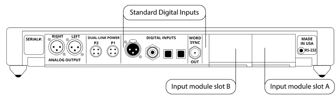
About the Input Module Slots
The DAC has two input module slots. They are labeled A and B. Input modules can be placed in either position. Each module is completely self-contained. It is recognized by theDAC and identified on the display. When the module is not in use, it is disabled.
Module Handling
It is important that you refrain from touching the circuit board or rear connector of any input module when removing or installing any input modules in your Digital Director. You should only handle it by the metal case of the module, or the front edge of the module where the cam arm is located. Improper handling of your modules can result in static shock and damage to the module and/or DAC.
Removing and Installing Modules
Removal and installation of modules is a tool-free process that is easily performed at the back of the unit. Under the lower lip of each module is a lever. Simply pull the lever out and away until it is perpendicular with the back of the unit. Then, gently, but firmly pull the module and lever until the module releases. Slide it out of the unit. Refer to the “Module Handling” portion of your manual before attempting.
Available Input Modules
If the digital inputs in the Digital Director do not fulfill your full digital input requirements, a list of the currently available modules and their intended uses are listed below. A full digital list of these inputs, as well as a comprehensive list of pros and cons for each input format, can be found online by scanning the following QR Code or by visiting the URL listed below.

www.msbtechnology.com/dacs/digital-inputs/
| Pro ISL | MSB proprietary interface for use with MSB sources. This module provides one input. |
| Renderer | A renderer interface for use on a home network or server. (See
Renderer manual for operation and setup details.) |
| MQA USB | A single USB interface for playback via a computer-based source. (See USB manual for operation and setup details.) |
| Optical/Coaxial S/PDIF | A Toslink and Coaxial digital input with a word-sync output. |
| XLR S/PDIF | A single XLR digital input with a word sync output. |
| ProI2S | MSB’s proprietary interface for use with classic MSB transports. This module provides two inputs. |
Burn-In
The feedback we receive leads us to recommend at least 100 hours of burn-in on this product. Customers generally report improvement in up to one month.
Updating Firmware
The following firmware instructions are for updating DAC and Digital Director firmware. If you do not have a Digital Director installed in your system, then ignore any Digital Director instructions. The firmware files are .WAV audio files.
Updating DAC Firmware – Before Digital Director Install
To start, if you have not installed your digital director in your system, first begin by updating the DAC firmware. This is important; your DAC will not recognize the Digital Director and the firmware updates will not work. Your Discrete DAC firmware must be updated to 21.14 or later. Please check your DAC firmware before installing your Digital Director. This can be done by scrolling through your DAC’s menu until you see the “Code” or “DAC Software” screen where the currently installed revision number will be displayed.
Begin by downloading both the Digital Director Firmware and the DAC firmware. Add these files to your bit perfect playback software. Please note, these must be played by a bit perfect source. If the update fails, it is not being played bit perfect. These updates include two upgrades within the same file. The file is several minutes long. Please do not interrupt the process and let the file finish to the end. When you play the file, you will hear instructions and two upgrade tones. Following each tone, you will either hear silence for about 30 seconds (this varies) or you will hear the message ‘upgrade failed’. If all the upgrades fail, it is because you did not play the file bit-perfect. You may have computer upsampling on or digital volume control somewhere in your playback system. The screen on the DAC will confirm when the upgrade is happening. Contact MSB if you need help.
After the DAC firmware is updated, you can now install your Digital Director. Please see our other video on Digital Director Setup for more specific instructions.
Updating Firmware with a Digital Director
For any updates after the initial setup, you will need to follow this order for updating.
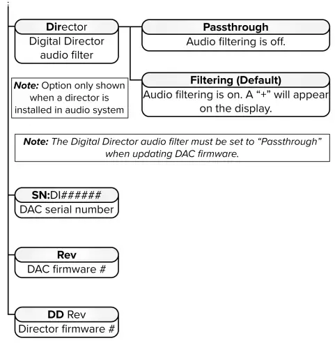
Power on the DAC and the director. Always begin by updating the DAC firmware first. The Firmware file will not be able to update the DAC while Digital Director processing is on. Enter the menu, scroll to the “Director” screen, then select “passthrough mode” for the Digital Director. This will allow the firmware update to reach the DAC bit perfect.
- Now, play the DAC firmware update. After the DAC firmware is installed and complete, you can now play the Digital Director firmware. Finally, go back into the menu and enable the Digital Director filtering again.
- After the firmware updates are complete, you can check for a successful connection between the Digital Director and DAC indicated by a small “+” sign on the display. If you do not see this “+” sign, the
- Digital Director is not performing the improved digital filtering. Please check the menu to see if the filtering is enabled. If it is, please check and confirm the currently installed firmware numbers reflect the new update files.
- If you see an error message with “Err” it means there is an issue with the quality of the ProISL connection or toslink control cable. Check your cables and replace them if need be.
- If you need further clarification or are encountering issues with your update, please reach out to our technical support team.

https://www.msbtechnology.com/dacs/discrete-dac-support/
Bit-Perfect Source Testing
Files can be downloaded from the MSB website to verify bit-perfect playback on any transport. They are .WAV music test files that, when played, will be identified and checked by the Digital Director. It will be reported on the display if they are bit-perfect. If there is a problem with the test, it will play, but the display will not indicate any change. Be sure upsampling is turned off in any transport, as this prevents a file from remaining bit-perfect. This system will allow you to easily test your source, especially computer sources, to see if all your settings are correct. There are files at all sample rates for both 16-bit and 24-bit operation. Detailed instructions can be found online by scanning the following QR Code or by visiting the URL listed below.

https://www.msbtechnology.com/support/bit-perfect-testing/
Premier Powerbase – Advanced Setup
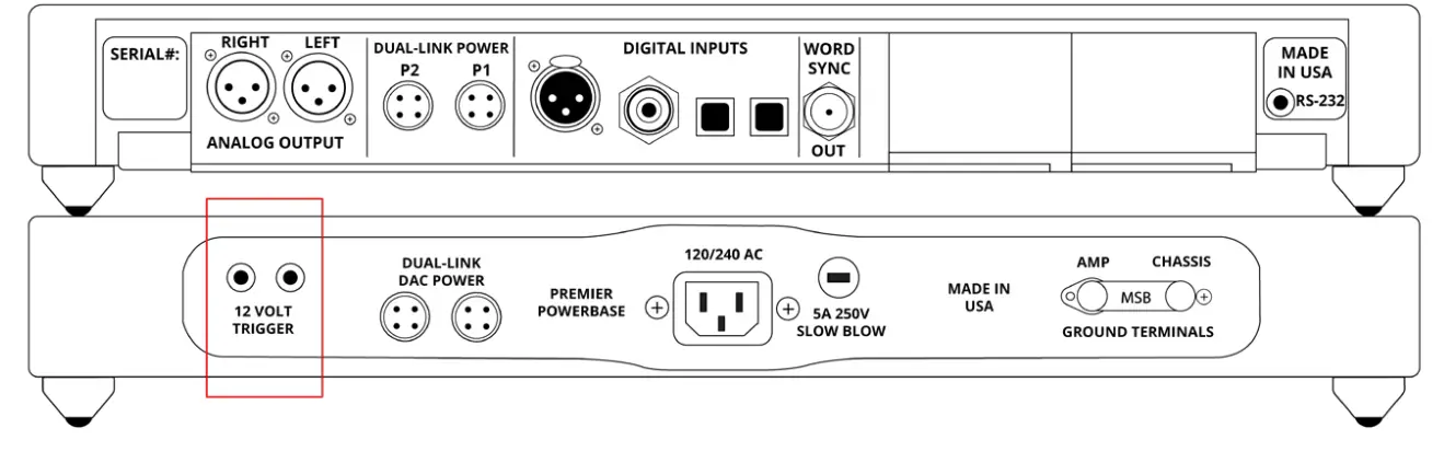
The Premier Powerbase comes with a few features that are not required for basic operation. These features are mainly used for altering your system setup and slight ease-of-use improvements. The 12-volt trigger is a network of 3.5mm mini-jack connections that can make your Premier Powerbase power button turn on/off your MSB amplifier(s) using the power button located on the faceplate or the power button on your remote to create a single power control for your entire MSB system. The second feature on the Premier Powerbase is a ground shield network that can offer a slight increase in sonic performance by connecting all of your MSB products in a chain and lifting the chassis ground connections.
Powerbase – 12 Volt Remote Trigger
The Premier powerbase is equipped with a remote trigger for use with other MSB products. The trigger uses a 3 pin mini jack. When any MSB product is turned off, the other products connected will also turn off and vice-versa. This trigger can also be used with other products. Products may use this trigger differently, so you may need an MSB 12Volt trigger adapter.
 Shielding Ground – Basic Operation
The Basic Operation provides isolation only for the DAC. This gets you half the shielding available. For full shielding, be sure the jumper is in place between the Chassis Ground and Amplifier Ground. This is the shipping configuration.
NEVER OPERATE WITHOUT THE JUMPER OR A GROUND WIRE ATTACHED.
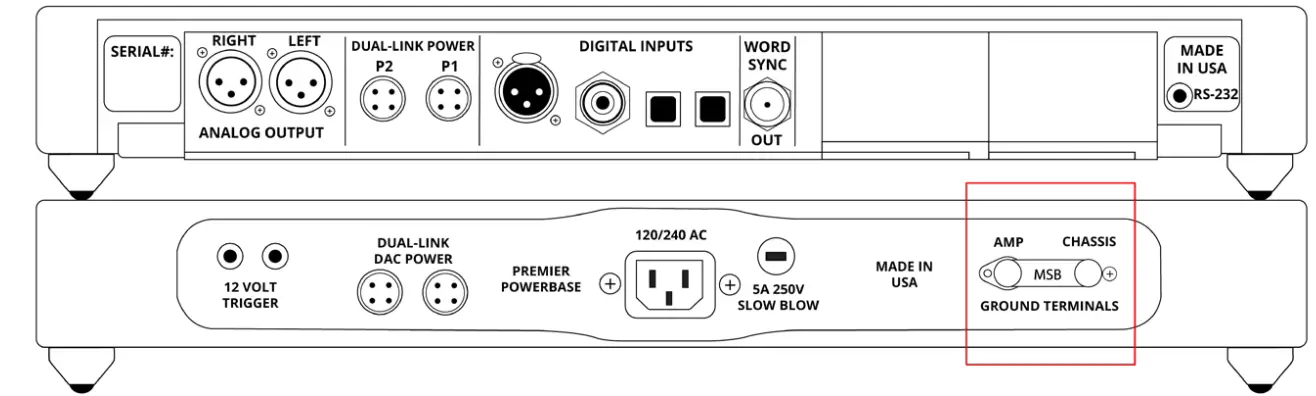
Shielding Ground – Enhanced Operation
The Enhanced Operation provides isolation for both the DAC and the amplifier. This gets you the full isolation available. With the jumper disconnected, connect the supplied ground wire from the AMPLIFIER GROUND lug to the chassis of the amplifier. Note this connection is dependent on the amplifier, so you will have to look for the best place to attach the wire. Generally, the easiest place would be to loosen a screw on the Amplifier Chassis and slip the open Spade lug under the screw head and tighten the screw. The only other place a true ground may be found is on the ground pin of the power connector to the AMP, but this will not be easy to connect to.
Enhanced Shielding Ground Operation – Diagram
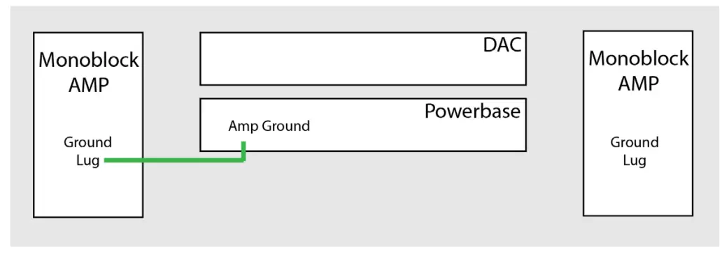
Grounding Lug Configuration
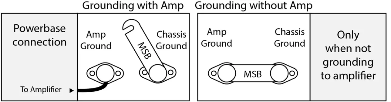
Powerbase Connection
Attach the ground wire to the “Amp ground” lug of the powerbase. Lift the jumper between “Amp Ground” and “Chassis Ground” as shown above.
Amp Connection
Attach the ground wire to the Ground Lug on the jack panel of the MSB amp. If there is is no ground lug, attach wire to a chassis screw. ***Never connect the ground wire to the negative speaker terminal***
The Discrete DAC Warranty Registration
All MSB Technology products come with a standard 2-year warranty. Details are defined below. We offer an additional 3 years of extended warranty for the original owner (a total of 5 years) if the following warranty registration form is completed within one year of the manufacture date. Instructions can be found online by scanning the following QR Code or by visiting the URL listed below.

www.msbtechnology.com/support/msb_warranty/
The Discrete DAC Limited Warranty
Warranty includes:
- MSB warranty covers the unit against defects in materials and workmanship for a period of 2 years from the original manufacture date.
- This warranty covers parts and labor only; it does not cover shipping charges or tax/duty. During the Warranty period, there will normally be no charge for parts or labor.
- During the warranty period, MSB will repair or, at our discretion, replace a faulty product.
- Warranty repairs must be carried out by MSB or our authorized dealer. Please contact your dealer if your unit requires service.
Warranty excludes:
- The Warranty does not cover standard wear and tear.
- The product is misused in any way.
- Any unauthorized modifications or repairs were performed.
- The product is not used in accordance with the Operating Conditions stated below.
- The product is serviced or repaired by someone other than MSB or an authorized dealer.
- The product is operated without a mains earth (or ground) connection.
- The unit is returned inadequately packed.
- MSB reserves the right to apply a service charge if the product returned for warranty repair is found to be operating correctly, or if the product is returned without a returns number (RMA) being issued.
Operating Conditions:
- Ambient temperature range: 32F to 90F, non-condensing.
- The supply voltage must remain within the AC voltage specified on the power base.
- Do not install the unit near heat sources such as radiators, air ducts, power amplifiers, or in direct, strong sunlight. This may cause the product to overheat.
Technical Support
If you are experiencing any issues with your MSB product, please contact your nearest dealer or try our support page at www.msbtechnology.com/support. Please be sure you have the most current edition of your products’ firmware installed. If your issue persists, please feel free to contact MSB directly. Emails are usually responded to in 1-2 business days. Email: hello@msbtechnology.com
MSB Return Procedure (RMA)
If a customer, dealer, or distributor has a problem with an MSB product, they should email tech support before sending anything back to the factory. MSB will do their best to respond within 1-2 business days. Should it be clear that a product must be returned, tech support should be informed and all the following relevant information should be provided:
| 1 | Product in question |
| 2 | Serial number |
| 3 | Exact configuration when symptom is observed, along with a list with the input used, source material, system connections, and amplifier |
| 4 | Customer name |
| 5 | Customer shipping address |
| 6 | Customer phone number and email |
| 7 | Special return shipping instructions |
MSB will issue an RMA number and create an invoice with all details outlined, except the final price as the product has not yet been seen. This invoice will be emailed so all the above information can be checked and verified by the customer.
The product should be returned with the RMA number present on the box. Work can then begin immediately and the product can be sent back quickly.
Any repair that is difficult and cannot be completed in two weeks will be identified, and the customer will be informed when it is to be expected. Otherwise, the majority of repairs should be shipped back within two weeks if all the required information is present on the invoice.
Link to page: www.msbtechnology.com/support/repairs/
Discrete DAC Specifications
| Supported Formats (Input dependent) | 44.1kHz to 3,072kHz PCM up to 32 bits 1xDSD, 2xDSD, 4xDSD, 8xDSD
Supports DSD via DoP on all inputs |
| Digital Inputs |
|
| XLR Analog Outputs | 3.57Vrms Maximum Galvanically isolated |
| Base XLR Output | 300 Ohm Balanced (High Gain) 150 Ohm Balanced (Low Gain) |
| Base RCA Output | 120 Ohm Low Gain Only |
| Volume Control | 1dB steps (Range 0 – 106).
Volume Control can be disabled in the menu. |
| Chassis Dimensions |
|
| Shipping Dimensions |
|
| Included Accessories |
|
| Warranty |
|
Discrete Supply Specifications
| AC Voltage | 100-120 / 240V (Switchable) |
| Power Consumption | 45 Watts with fully configured Discrete DAC |
| Chassis Dimensions |
|
| Shipping Dimensions |
|
| Included Accessories |
|
| Warranty |
|
Premier Powerbase Specifications
| AC Voltage | 100 / 120 / 240V (Auto Switching) |
| Power Consumption | 45 Watts with fully configured Discrete DAC |
| Chassis Dimensions |
|
| Shipping Dimensions |
|
| Included Accessories |
|
| Warranty |
|
The Discrete DAC
User Guide
Check our website for the most recent user guides, firmware and drivers at: www.msbtechnology.com
Technical support email is: Hello@msbtechnology.com
01.15.2025
Frequently Asked Questions (FAQ)
Q: How do I disconnect a Dual-link cable?
A: To disconnect a Dual-link cable, pinch the portion with the flat portion and arrow symbol, then pull back from the jackpanel without twisting or rotating.
Documents / Resources
 |
MSB TECHNOLOGY The Discrete DAC interface Network Renderer V2 Streaming Decoding [pdf] User Guide The Discrete DAC interface Network Renderer V2 Streaming Decoding, The Discrete DAC, interface Network Renderer V2 Streaming Decoding, Network Renderer V2 Streaming Decoding, Renderer V2 Streaming Decoding, Streaming Decoding |


