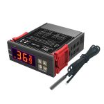
LILYTECH ZL-6231A Temperature Controller

Introduction
ZL-6231A thermostat is for cooling or heating control, with IP65 front panel, buzzer beeping and warning function. There is a multifunction timer which is for incubator air exhaustion, or egg tray turning, or other application.
Specification
- Power supply: 185~245Vac, 50/60Hz
- Sensor: NTC, wire length is 2 meters
- Output: 10A, 250Vac resistance
- Setting range: -40~120℃
- Display range: -40~130℃
- Working: -10~45℃, 5~90%RH without dew
- Dimension: W78 x H34.5 x D71 (mm)
- Installation drilling: W71 x H29 (mm)
- Case materials: PC + ABS fire proof
- Protection level: IP65 (Front side only)
Display

| Icon | Function | On | Off | Blinking |
| |
R1 temp. control output | R1 Temp. Output energized | R1 Temp. Output de-energized | Within protecting delay |
| |
Work mode |
Cooling mode |
—- |
Setting set-point |
| |
Heating mode | |||
| |
Maintenance | —- | No failure | Has failure |
| |
Warning | —- | No warning | Has warning |
| |
R2 output | R2 energized | R2 de-energized | |
| |
Egg turn times reached | —- | —- | U46 > U45 (when U45 not equal zero) |
| Display | Remark |
| E01 | Sensor failure (short or open) |
| Hi | Room temp. is higher than the high limit |
| Lo | Room temp. is lower than the low limit |
| EE | Memory error |
| Err | Password error |
| iA | External warning |
| UnL | Parameters Will restore to factory default settings |
Power up Display
The model (ZL-6231A) and software version (Version 2.0) will display after power supplied:

Operation
Set Set-Point (Factory Default Setting = 37.8℃)
- Keep〖S〗depressed for 3 seconds to enter into the status. The current set-point value displays.
- Press〖▲〗or〖▼〗to set the value (keeping depressed can fast set).
- Press〖S〗to exit, and save the settings.
The status will exit, and the setting will not be saved if no key operation within 30 seconds.
Set System Parameters
- Keep〖P〗depressed for 3 seconds, digits show “—0”.
- Press〖▼〗to select the digit of the password, press〖▲〗to set the value of the digit.
- Press〖S〗to confirm: If the password is correct, enter into the parameter setting status, else display “Err”, and exit.
Set in parameter setting status:
- Press〖▲〗or〖▼〗to select the parameter code (see parameter code table below).
- Press〖S〗to display the value of the code. Press〖▲〗or〖▼〗to set the value. Press〖S〗to return to parameter code selection.
- Keep〖P〗depressed for 3 seconds to exit, and save the settings.
The status will exit, and the settings will not be saved if no key operation for 30 seconds.
Parameter Code Table
| Code | Function | Range | Remark | Factory Default |
| U10 | Minimum time for Temp. Output to keep de-energized | 0 ~ 100 min | Only for cooling | 0 |
| U20 | Sensor calibration | -9.9 ~ +9.9℃ | 0.0 | |
| U22 | Hysteresis for temperature control | 0.1 ~ +10.0℃ | 0.1 | |
| U40 | Timer period 1, time unit | 0 ~ 2 | 0: sec; 1: min; 2: hour | 0 |
| U41 | Timer period 1, time | 1 ~ 9999 | R2 on | 30 |
| U42 | Timer period 2, time unit | 0 ~ 2 | 0: sec; 1: min; 2: hour | 1 |
| U43 | Timer period 2, time | 1 ~ 9999 | R2 off | 60 |
| U44 | R2 working mode | 1 ~ 2 | 1: Timer output
2: Timer output + limit_protection |
2 |
| U45 | Timer repeats times | 0 ~ 9999 | If 0: Timer never stops running
Else: R2 never on, when U46 reaches U45 |
0 |
|
U46 |
Timer counter
(the value saved to permanent memory once every hour, keeps even without power supply) |
0 ~ 9999 |
One period = timer period 1 + timer period 2
Clear to 0 before every hatching |
0 |
| U52 | Over temp. warning delay | 0 ~ 180 min | 0 | |
| U53 | 1st over temp. warning delay after power supplied | 0 ~ 180 hour | 0: disable | 0 |
| U54 | Temp. up limit (relative value) | 0.0 ~ 120.0℃ | Absolute point = (Set-point + U54) | 0.2 |
| U55 | Temp. low limit (relative value) | 0.0 ~ 120.0℃ | Absolute point = (Set-point – U55) | 37.8 |
|
U60 |
External input warning mode |
0 ~ 4 |
0: disable 3: NC, locked
1: NO, locked 4: NC, unlocked 2: NO, unlocked |
0 |
| U61 | Delay for external input warning | 0 ~ 120 min | 0 | |
| U62 | Buzzing warning | 0 ~ 1 | 0: no waring / 1: enable warning | 0 |
| U90 | Control mode | CO/HE | CO: cool / HE: heat | HE |
| U99 | Password | 0000 ~ 9999 | When 0000, equals no password | 0000 |
Note:
- U46 will be saved to permanent memory once every hour.
- Limit Protection:
- Troom: Temperature of the room.
- SP: Temperature set point.
- When U44 = 2:
If Troom ≥ SP + U54 in heating mode (U90 = HE), or if Troom ≤ SP – U55 in cooling mode (U90 = CO), then R2 will be energized.
Control
- Cooling Control (U90 = C0)
- If Troom ≥ Set-point + U22, and Temp. Output has been de-energized for U10, then Temp. Output energized.
- If Troom ≤ Set-point, then Temp. Output de-energized.
- Heating Control (U90 = HE)
- If Troom ≤ Set-point – U22, then Temp. Output energized.
- If Troom ≥ Set-point, then Temp. Output de-energized.
- Temp. Output Load Delay Protection (only for cooling control)
- After power supplied, Temp. Output could be energized after U10;
- After Temp. Output de-energized, it could be energized again after U10.
- Buzzer Function
Every key press, there will be a short beep. Every confirmation key press, there will be a long beep. Every error operation, there will be three short beeps.
When there is failure, or external warning input: If U62 = 0, no buzzing warning. If U62 = 1, there will be continuous buzzing of warning.
The waring will stop, if press〖P〗, or warning condition disappears. - External Warning Input
- NO: normal open. If open, no warning; if closed, warning.
- NC: normal close. If closed, no warning; if open, warning.
- Locked: Warning keeps after the external warning disappeared. Press〖P〗 to stop warning.
- Unlocked: Warning stops after the external warning disappeared.
Note: When there is external warning, the output(s) will be de-energized.
- Sensor Fail
R1 stop energized. - Sensor Calibration
The sensor can be calibrated by U20. - Restore to Factory Default Settings
Keep〖P〗and〖▲〗depressed simultaneously for 5 sec, there will be a beep, and “UnL” displays.
Press〖▼〗twice, there will be a beep, all settings will be restored to factory default settings.
Installation
1st: Insert into drilling hole

Attention
- Wiring work should be manipulated by certified technicians.
- Wrong connection could damage the controller, and the loads. Power supply to terminal 7 and 8 to check the controller. If there is a multimeter, check the outputs, as well as input, by the help of settings.
- Sensor and input signal wires should not be laid together with power supply wire, and even in same pipe.
- Sensor wire is better as short as possible. Not wind the redundant length wire to electrical noise equipment.
- The loads should be within the specification of the controller output driving ability. If using ac/dc module as load, or tungsten lamp, or motor, following the below requirements to avoid surging current damaging or shorten the lifetime of the controller outputs:
- For ac/dc module as load, the rated current should be no more 1/10th of output specification under pure resistance.
- For tungsten lamp as load, the rated current should be no more 1/15th of output specification under pure resistance.
- For motor, the rate current should be no more 1/5th of output specification under pure resistance.
- For example: if drive a 1500W tungsten lamp with 7A (pure resistance spec.) relay, the relay contactor will be burnt immediately.
- Don’t touch inside components.
- Avoid installing controller in the following environment:
More wet than 90%RH, or easily dew; Vibrating, or will be shocked; Possible sprayed; Under erosive air; Under explosive air.
Electrical Wiring

Documents / Resources
 |
LILYTECH ZL-6231A Temperature Controller [pdf] Instruction Manual ZL-6231A Temperature Controller, ZL-6231A, Temperature Controller, Controller |
 |
LILYTECH ZL-6231A Temperature Controller [pdf] Instruction Manual ZL-6231A Temperature Controller, ZL-6231A, Temperature Controller, Controller |