INSTRUO dail Eurorack Pattern Quantiser Module Elevator Sound
Product Usage Instructions
- The CV Input accepts bipolar control voltage for quantization.
- Connect your control voltage source to this input.
- The Signal Throughput input accepts bipolar control voltage.
- Connect existing signals to be offset or quantized to this input.
FAQ
- Q: How do I update the firmware of the Quantiser module?
- A: To update the firmware, download the latest firmware version from the manufacturer’s website and follow the provided instructions for installation.
Description
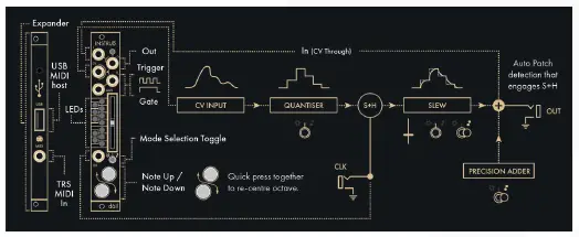
- The Instruō dàil is a high-resolution quantizer, precision adder, MIDI-to-CV interface, and USB MIDI Host with a very small form factor suitable for any system.
- As a quantizer, scales can be defined locally as well as externally via MIDI.
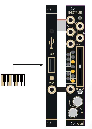
- The USB Host port will accept and power class-compliant devices offering convenience and immediacy to melodies and sequences.
- As a precision adder, existing signals can be offset by any defined chromatic interval. Transpose anything with accuracy using the calibrated buffered throughput which runs parallel to the quantiser engine. This feature alone makes for a great companion to any sequencer or 1V/octave source within a system.
- No longer is a single repeating octave of quantized notes a limitation. dàil features a fully bipolar quantizer engine through which any multi-octave spanning scale/chord/arpeggio can be engaged immediately from your MIDI keyboard. Patterns can also be programmed onboard with precision with the ability to auto-fill from a wide range of major and minor starting points.
- Small form factor, big feature set! dàil will suit any scale of system adding flexibility and immediacy to your melodic needs.
Features
- Multi-octave pattern quantizer
- On-board and MIDI controllable scale programming
- Chromatic interval precision adder
- MIDI-to-CV interface
- USB MIDI host for class-compliant controllers
- Includes 2 HP MIDI Expander
- Includes 5-pin DIN to TRS MIDI Type-A adapter
- TRS MIDI Type A and Type B compatibility
Installation
- Confirm that the Eurorack synthesizer system is powered off.
- Locate 4 HP of space in your Eurorack synthesizer case. Locate an additional, but optional, 2 HP of space in your Eurorack synthesizer case for the included expander.
- If the optional expander is desired, connect the 8-pin side of the IDC expansion cable to the 2×4-pin headers on the back of the main module, confirming that the red stripe on the expansion cable lines up with the indicator on the main module.
- If the optional expander is desired, connect the 8-pin side of the IDC expansion cable to the 2×4-pin headers on the back of the expansion module, confirming that the red stripe on the expansion cable lines up with the indicator on the expansion module.
- If the optional expander is desired, connect the Expansion Back Jacks on the back of the main module and expander together with the included 3.5mm TRS Cable
- Connect the 10-pin side of the IDC power cable to the 2×5-pin header on the back of the module, confirming that the red stripe on the power cable is connected to -12V.
- Connect the 16-pin side of the IDC power cable to the 2×8-pin header on your Eurorack power supply, confirming that the red stripe on the power cable is connected to -12V.
- Mount the Instruō dàil in your Eurorack synthesizer case.
- Power your Eurorack synthesizer system on.
Note
- This module has reverse polarity protection.
- Inverted installation of the power cable will not damage the module.
Specifications
- Width: 4 HP + 2 HP MIDI Expansion Module
- Depth: 32mm
- +12V: 100mA*
- -12V: 8mA
The current draw on +12V will increase when powering a USB device.
dàil (verb) divides something into parts. (noun) a part of a whole.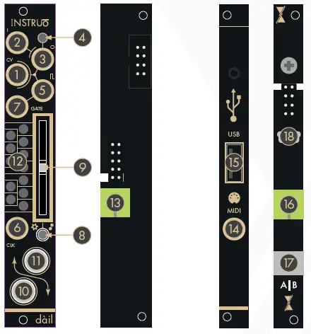
Key
- CV Input (CV)
- Signal Throughput (In)
- Output (Out)
- Output Indicator
- Trigger Output
- Clock Input (Clk)
- Gate Output
- Interface Selection Toggle
- Slider
- Button 1
- Button 2
- Voltage Indicators
- Expansion Back Jack
- TRS MIDI Input
- USB Type A Port (USB)
- Expansion Back Jack
- A|B Switch
- USB Type B Mini Port
dàil
![]() CV Input (CV): The CV Input is a bipolar control voltage input for the quantizer.
CV Input (CV): The CV Input is a bipolar control voltage input for the quantizer.
- The control voltage present at the CV Input will be quantized to the programmed scale (See the Programming Interface section for more information).
- Input Range: -/+10V
![]() Signal Throughput (In): The Signal Throughput is a bipolar control voltage input.
Signal Throughput (In): The Signal Throughput is a bipolar control voltage input.
- Signals present at the Signal Throughput will sum with the voltage produced by the quantizer and can be used for transposition.
- The Precision Adder bias will sum at the Output.
- Input Range: -/+10V
![]() Output (Out): The Output is a bipolar control voltage output that generates the summed signal of the quantized CV Input, the Signal Throughput, and the Precision Adder.
Output (Out): The Output is a bipolar control voltage output that generates the summed signal of the quantized CV Input, the Signal Throughput, and the Precision Adder.
- Output Range: -/+10V
![]() Output Indicator: The Output Indicator provides LED illumination of the signal present at the Output.
Output Indicator: The Output Indicator provides LED illumination of the signal present at the Output.
- As the signal increases from 0V to a positive value, the Output Indicator illuminates white and increases in brightness.
- As the signal increases from 0V to a negative value, the Output Indicator illuminates amber and increases in brightness.
![]() Trigger Output: The Trigger Output generates a trigger signal with every update in quantized voltage.
Trigger Output: The Trigger Output generates a trigger signal with every update in quantized voltage.
- Output Voltage: 5V
![]() Clock Input (Clk): The Clock Input is an external clock input for the quantizer engine’s optional sample and holds the stage.
Clock Input (Clk): The Clock Input is an external clock input for the quantizer engine’s optional sample and holds the stage.
- An external rising-edge signal present at the Clock Input allows for external clocking of a sample and hold implemented after the quantizer engine before slew is applied. AND logic is applied if the quantizer has a new note and a rising edge is received at the Clock Input. A trigger signal will be produced at the Trigger Output and the Output will update.
![]() Gate Output: The Gate Output generates a gate signal for the duration of any sustained MIDI note message present at the USB Type A Port or TRS MIDI Input of the MIDI Expander (See the MIDI-to-CV Interface/USB MIDI Host section for more information).
Gate Output: The Gate Output generates a gate signal for the duration of any sustained MIDI note message present at the USB Type A Port or TRS MIDI Input of the MIDI Expander (See the MIDI-to-CV Interface/USB MIDI Host section for more information).
![]() Interface Selection Toggle: The Interface Selection Toggle selects the operational interface page (See the Programming Interface, Quantiser Interface, and Precision Adder Interface sections for more information).
Interface Selection Toggle: The Interface Selection Toggle selects the operational interface page (See the Programming Interface, Quantiser Interface, and Precision Adder Interface sections for more information).
- If the toggle is in its left position, the Programming Interface is selected.
- If the toggle is in its center position, the Quantiser Interface is selected.
- If the toggle is in its right position, the Precision Adder Interface is selected.
Slider: The Slider is a multi-purpose manual control
 Button 1: Button 1 is a multi-purpose manual control (See the Programming Interface, Quantiser Interface, and Precision Adder Interface sections for more information).
 Button 2: Button 2 is a multi-purpose manual control (See the Programming Interface, Quantiser Interface, and Precision Adder Interface sections for more information).
 Voltage Indicators: The Voltage Indicators provide LED illumination of voltage values available in the Quantiser and Precision Adder Modes (See the Programming Interface, Quantiser Interface, and Precision Adder Interface sections for more information).
 Expansion Back Jack: The Expansion Back Jack is a 3.5mm TRS jack used for connecting the included MIDI Expander to the main module.
MIDI Expander
 TRS MIDI Input (MIDI): The TRS MIDI Input allows for MIDI-to-CV conversion via a DAW or MIDI controller. (See the MIDI-to-CV Interface section for more information).
 USB Type A Port (USB): The USB Type A Port allows for USB MIDI hosting of a MIDI Controller. (See the USB MIDI Host section for more information).
- It’s recommended to use MIDI controllers that are bus-powered and class-compliant.
- It should be noted that the current draw on the +12V rail will vary depending on the current requirements of the device connected.
 Expansion Back Jack: The Expansion Back Jack is a 3.5mm TRS jack used for connecting the included MIDI Expander to the main module.
 A|B Switch: The A|B Switch changes the compatibility of dàil to work with either TRS MIDI Type A adapters (included) or TRS MIDI Type B adapters.
- The switch is set to Type A compatibility by default.
Programming Interface
 Programming Interface allows for the activation and deactivation of chromatic intervals for the quantizer and precision adder. It also allows for the selection of preset scales.
Voltage Indication
 An activated quantizer chromatic interval is indicated by amber LED illumination of the corresponding Voltage Indicator, and Button 1 will change from a dull amber illumination to a bright amber illumination when the Slider has navigated to its location.
 An activated precision adder chromatic interval is indicated by white LED illumination of the corresponding Voltage Indicator, and Button 2 will change from a dull white illumination to a bright white illumination when the Slider has navigated to the corresponding location.
 If a chromatic note is activated for both the quantizer and precision adder, it is indicated by “soft white” (a combination of both amber and white LEDs) illumination of the corresponding Voltage Indicator. Button 1 and Button 2 will also change from a dull illumination to a bright illumination when the Slider has navigated to the corresponding chromatic location.
 If a chromatic note is deactivated for both the quantizer and precision adder, it is indicated by no illumination of the corresponding Voltage Indicator and Button 1 and Button 2 will change from a bright illumination to a dull illumination when the Slider has navigated to the corresponding location.
Programming Chromatic Intervals
- Set the Interface Selection Toggle to its left position.
- Visualize the Voltage Indicators as a chromatic keyboard.
- Use the Slider to navigate the desired chromatic note press Button 1 to activate and deactivate it for the quantizer and press Button 2 to activate and deactivate it for the precision adder.
Drag and Fill Activation of Chromatic Intervals
- Set the Interface Selection Toggle to its left position.
- Use the Slider to navigate to the desired chromatic note and ensure that the note is deactivated.
- If it’s activated, press Button 1 to deactivate it for the quantiser, or press Button 2 to deactivate it for the precision adder.
- Press and hold Button 1 and move the Slider up and/or down to activate any adjacent chromatic notes for the quantizer.
- Press and hold Button 2 and move the Slider up and/or down to activate any adjacent chromatic notes for the precision adder.
- Release Button 1 and/or Button 2.
Drag and Fill Deactivation of Chromatic Intervals
- Set the Interface Selection Toggle to its left position.
- Use the Slider to navigate to the undesired chromatic note and ensure that the note is activated.
- If it’s deactivated, press Button 1 to activate it for the quantizer or press Button 2 to activate it for the precision adder.
- Press and hold Button 1 and move the Slider either up and/or down to deactivate any adjacent chromatic notes for the quantizer.
- Press and hold Button 2 and move the Slider either up and/or down to activate any adjacent chromatic notes for the precision adder.
- Release Button 1 and/or Button 2.
Programming Voltages via MIDI
- Connect a MIDI controller to dàil via the USB Type A Port or the TRS MIDI Input on the MIDI Expander.
- Use the MIDI controller to select and deselect notes by playing chords.
- Press and hold down each note together to activate the corresponding voltage.
- With the notes held down, toggle a note on by adding it to the played voicing (notes must be sustained for >200ms to latch on). To deactivate the corresponding voltage play the note staccato (note duration must be <200ms).
Selecting Preset Major Scales
- Set the Interface Selection Toggle to its left position.
- Set the Slider to its lowest position.
- Press and hold Button 1 for the quantizer and/or Button 2 for the precision adder and move the Slider to its highest position, then lowest position, then highest position again.
- A major triad will be illuminated on the Voltage Indicators.
- With the button still pressed down, move the Slider to its lowest position, then the highest position to autofill the next preset major scale.
- Keep repeating this gesture until the desired major scale is selected.
- Release the button.
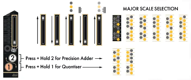
The preset major scales are
- Major Triad
- Major Pentatonic
- Major 7th
- Ionian (Major)
- Lydian
- Mixolydian
- Ionian #5 (Augmented Major)
- Whole Tone
Selecting Preset Minor Scales
- Set the Interface Selection Toggle to its left position.
- Set the Slider to its highest position.
- Press and hold Button 1 for the quantizer and/or Button 2 for the precision adder and move the Slider to its lowest position, then highest position, then lowest position, then highest position again.
- A minor triad will be illuminated on the Voltage Indicators.
- With the button still pressed down, move the Slider to its lowest position, then the highest position to autofill the next preset minor scale.
- Keep repeating this gesture until the desired minor scale is selected.
- Release the button.
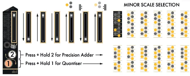
The preset minor scales are
- Minor Triad
- Minor 7th
- Minor Pentatonic
- Diminished
- Aeolian (Natural Minor)
- Harmonic Minor
- Dorian
- Phrygian
- Super-Locrian (Altered Diminished)
- Phrygian Dominant with Chromatic Leading Tones
- Melodic Minor (Ascending Pattern)
Quantiser Interface
Quantiser Interface allows for quantization of the signal present at the CV Input.
- Any changes made in the Programming Interface will not be committed until dàil enters the Quantiser Interface.
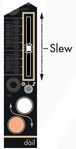
- In the Quantiser Interface, the Slider sets a global slew amount for the quantiser.
- The slider’s LED will illuminate white and increase in brightness as the slew amount is increased.
Octave-Offsetting Quantised Voltage
In Quantiser Mode, Button 1 and Button 2 are used to globally offset the quantized voltage present at the Output by perfect octaves.
- Button 1 will offset the quantized voltage negatively by up to 9V (9 octaves). The button will illuminate white when an octave offset is applied.
- Button 2 will offset the quantized voltage positively by up to 9V (9 octaves). The button will illuminate white when an octave offset is applied.
- Press both buttons to reset the octave offset voltage to 0V.

Precision Adder Interface
Precision Adder Interface allows for a chromatic offset of the signal present at the Output.
- Any changes made in the Programming Interface will not be committed until dàil enters the Precision Adder Interface.
- In the Precision Adder Interface, the Slider sets a global slew amount for the quantiser.
- The slider’s LED will illuminate white and increase in brightness as the slew amount is increased.
- The slew is applied to the Quantiser Interface signal only.
- Precision Adder Interface offsets will be applied immediately.
Chromatic-Offsetting Quantised Voltage
- In the Precision Adder Interface, Button 1 and Button 2 are used to globally offset the voltage present at the Output by the defined chromatic divisions.
- Button 1 will provide a negative voltage offset of up to -9V (9 octaves).
- The button will illuminate white when an octave offset voltage is applied.
- Button 2 will provide a positive voltage offset of up to +9V (9 octaves).
- The button will illuminate white when an octave offset voltage is applied.
- Press both buttons to reset the offset voltage to 0V.
Distribution Modes
Natural Distribution Mode allows the quantizer to consider the distance between individual notes and only change the quantized state when the corresponding threshold voltage has been met at the CV Input.
- When Quantiser Interface is selected and Button 2 is pressed, Natural Distribution Mode is indicated by a pulsing amber Button 1.
- Equal Distribution Mode allows the quantizer to equally distribute the quantized voltages regardless of the distance between individual notes.
- The number of defined notes will automatically and dynamically be distributed to equal distant thresholds across the number of octaves they are defined within.
- When Quantiser Interface is selected and Button 2 is pressed, Equal Distribution Mode is indicated by a pulsing amber Button 2.
- To change between both Distribution Modes, engage the Quantiser Interface, press and hold Button 1, and then tap Button 2.

MIDI-to-CV Interface
- To enter the MIDI-to-CV Interface, press and hold both buttons for 2 seconds.
- To exit the MIDI-to-CV Interface, press and hold both buttons for 2 seconds.
MIDI Interfacing
- As a USB MIDI Host, dàil can be connected to a MIDI controller via the USB Type A Port.
- Class-compliant devices will connect directly to the dàil expander for USB MIDI control (class compliance is standard, but there are only so many brands/devices that we could test in-house! Please check with the service team for any active list of confirmed compatibility of devices).
- The optimum current consumption of a USB MIDI device is up to 500mA.
- The current draw on the +12V rail will increase when powering a USB device. Please plan accordingly.
- dàil can be connected to a MIDI controller or a MIDI interface via its included TRS MIDI Type-A adapter. Through this adapter, a legacy 5-pin DIN MIDI connection can be used.
- By default, MIDI can be used to dynamically program the Quantiser engine’s scale. In the MIDI-to-CV Interface, dàil functions as a more traditional monophonic MIDI interface with producing 1V/octave (including pitch bend), gate, and trigger signals relating to MIDI note input.
Firmware Update
- Power dàil off
- Unmount both the main module and the MIDI expander from the system
- Ensure that the MIDI expander is fully connected to the main module.
- Connect the USB Type B Mini Port on the back of the MIDI Expander to a computer.
- Press and hold the Firmware Update Button while powering dàil on, ensuring that nothing could potentially short-circuit the module while powered on.
- dàil will show up as a storage device on the computer.
- Drag the firmware file to the root directory of dàil.
- Once the firmware update file is copied, dàil will unmount from the computer and reboot.
- The firmware has now been updated.
- Power dàil off and mount it back into the system.
CONTACT
- Manual Author: Collin Russell
- Manual Design: Dominic D’Sylva
- This device meets the requirements of the following standards: EN55032, EN55103-2, EN61000-3-2, EN61000-3-3, EN62311
Documents / Resources
 |
INSTRUO dail Eurorack Pattern Quantiser Module Elevator Sound [pdf] User Manual dail Eurorack Pattern Quantiser Module Elevator Sound, dail, Eurorack Pattern Quantiser Module Elevator Sound, Pattern Quantiser Module Elevator Sound, Quantiser Module Elevator Sound, Module Elevator Sound, Elevator Sound |