![]()
MAKING MODERN LIVING POSSIBLE
Manual
Liquid Level Controller
EKC 347
Manual
EKC 347 Liquid Level Controller
The parameter list in this technical leaflet is valid for software versions 1.1x .
Introduction
The EKC 347 is a PI liquid level controller that can be used for regulation of refrigerant level in:
- Pump packages
- Separators
- Intermediate coolers
- Economizers
- Condensers
- Receivers
A signal transmitter constantly measures the refrigerant liquid level in the receiver. The controller receives the signal. Its user-selected program controls the valve to regulate the refrigerant level to the user-specified setpoint.
Valve compatibility
The EKC 347 can control liquid level in systems with these valves:
- Type ICM motorized modulating valve with ICAD motor actuator
- Types AKV or AKVA pulse width modulating expansion valve
- Solenoid valve for on-off control
Features
- Generates alarm when user-programmed limits are exceeded
- 3 relay outputs for upper and lower level limits and for alarm level
- Accepts analog input signal that can offset the liquid level setpoint
- Controls liquid level on high or low pressure side of the system
- When AKV/A is selected, a master-slave system can run up to 3 AKV/A valves with distributed opening degree
- Manual control of output
- Able to limit minimum and maximum valve opening degree.
Ordering
| Type | Function | Code No. |
| EKC 347 | Liquid level controller | 084B7067 |
Application examples
Pump package (liquid separator)
Modulating control of injection provides more stable liquid level and more stable suction pressure.

Receiver or condenser
The control system’s short reaction time makes it well suited for high pressure float systems with small refrigerant charges.

Multiple AKV/A control in master-slave configuration
The schematic drawing below shows how multiple controllers can be used to control multiple AKV/A valves.

Operating the EKC 347
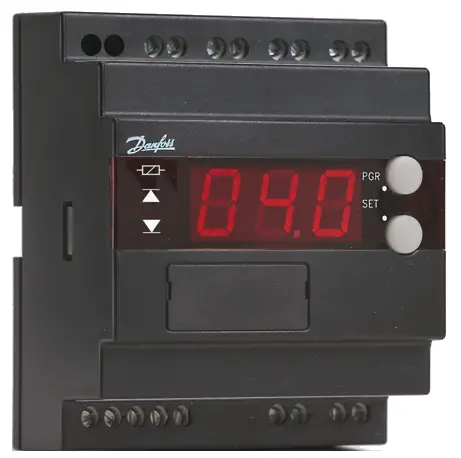
The Display
The EKC 347 has a three character digital display. Four status LEDs (Light Emitting Diodes) are to the left of the numerals. To the right of the display are two push buttons.
By default, the display normally shows the liquid level %, but user programming allows the valve’s opening degree to be selected as the normal display. At any given time, depressing the lower pushbutton will change from the normal display to the other value (liquid level % or valve opening %), which will be displayed for 5 seconds.

The Front Panel LEDs
The upper LED indicates that a signal is being sent to open a pulsewidth modulated valve type AKV/A or a solenoid valve that is being controlled for on-off applications.
The upper LED will has no function when using the EKC 347 with a motorized valve type ICM/ ICAD.
The three lower LEDs are used to indicate an alarm or an error in regulation. The diagram to the right shows the meanings of the symbols. If, for example, alarm A3 is detected, or there is an error in regulation, all three LEDs will flash. In this situation, pushing the upper button for 1 second will cause “A3” or the error code to be displayed. If both an alarm and an error occur simultaneously, only the error code will be displayed.

When an alarm code is displayed by pushing the upper button, the alarm relay A3 will be cut out.
The error (prefix E), alarm (prefix A), and status (prefix S) codes that can be displayed are given in the table below, along with the meaning of each code.
| Code | Description |
| E1 | Errors in the controller |
| E12 | Analog input value on terminals 19 & 21 or 20 & 21 is out of range |
| E21 | No signal from the liquid level sensor, or the signal value is out of range* |
| E22 | Valve position feedback on terminals 17 & 18 is out of range |
| A1 | High level alarm A1 has been detected |
| A2 | Low level alarm A2 has been detected |
| A3 | Additional level alarm A3 has been detected |
| S10 | Level regulation stopped by internal (parameter r12) or external (terminals 1 &2) start-stop |
| S12 | High or low level alarm has been detected when not using alarm A3 as a common alarm |
* If the signal is lost from the liquid level sensor, the controller will force the valve to the fully closed position if parameter n35 is 0 or, the controller will force the valve fully open if parameter n35 is 1. But if a maximum or minimum valve opening degree (parameters n32 and n33, respectively) has been set, then the valve will be forced to the set limits, not beyond.
Operating the EKC 347
To view or change liquid level set point:
 |
To enter change mode Press both buttons simultaneously |
 |
To raise the setpoint Press the upper button |
 |
To lower the setpoint Press the lower button |
 |
To save the change Press both buttons simultaneously |
To change a parameter setting:
 |
To access parameter menu Press the upper button for 5 seconds, then Use the upper and lower buttons to scroll through the parameter list |
 |
To enter change mode for a parameter you have scrolled to Press the both buttons simultaneously |
 |
To increase the setting Press the upper button |
 |
To decrease the setting Press the lower button |
 |
To save the new setting and return to the parameter menu Press both buttons simultaneously. You can then make other parameter changes or, The EKC 347 will exit the parameter menu and return to its normal display when no buttons have been pressed for approximately 18-20 seconds. |
To reset to factory default values:
1) Remove the supply voltage to the EKC 347
2) While pressing both buttons simultaneously, restore power. Factory settings will have been restored.
Quick setup guides
Quick setup guide when programming the EKC 347 for use with ICM Motorized valve with ICAD motor-actuator
The factory settings for the EKC 347 assume that it will be used on the low pressure side of the system to regulate an ICM motorized valve with ICAD motor-actuator, using a 4-20 mA signal, and a level probe type AKS 4100U. For most applications using these components, only the following settings will need to be changed:
- Set the user-defined liquid level percentage to be maintained.
Note that this setting does not have a parameter and is accessed by pushing both EKC 347 buttons simultaneously when the controller is showing the standard display (not in programming mode). - Set user-defined parameter n04. This is the P-band in percent liquid level, the liquid level range around the liquid level setpoint in which the controller will try to regulate. See regulation example 1 at right for more details.
- Change parameter o12 to 1 (for 60 Hz), the frequency of the controller power supply (unless the supply is 50 Hz).
- Set user-defined alarm parameters. See the alarm section in “Alarm parameters.”
Note that some applications will require that additional settings be changed. Review the settings and parameters on the following pages to ensure that the controller is completely set up for your application.
Quick setup guide when using a solenoid on-off control on low pressure side of the system
For this application, the following settings must be programmed:
- Parameter o09: 3 or 4, depending on the output on terminals 2 and 5
- Enter the user-defined setpoint (the liquid level % to be maintained). Note that this setting does not have a parameter and is accessed by pushing both EKC 347 buttons simultaneously when the controller is showing the standard display (not in programming mode).
- Set the user-defined differential (dead band), parameter n34, to the % liquid level around the setpoint that defines the dead band.
The valve will be opened and closed as shown in the diagram at right. - Set the P-band (parameter n04) to 0%, which corresponds to OFF (parameter n04 = 0).
- Change the frequency of the controller to 60 Hz (parameter o12 = 1).
- Set user-defined alarm parameters according to your requirements and your application
Note that some applications will require that additional settings be changed. Review the settings and parameters on the following pages to ensure that the controller is completely set up for your application.

Regulation example 1. Valve opening percentage will modulate to maintain the setpoint liquid level percentage. The P-band defines the liquid level percentage range allowed.

Regulation example 2. When the controller is set up for the low pressure side of a system, the solenoid valve will open and close as shown in the diagram above.
Level control settings
The parameter list in this technical leaflet is valid for software versions 1.1x .
| Description of setting | Parameter | Minimum | Maximum | Factory setting | Field setting |
| Liquid level setpoint This setting is not changed by entering the parameter list, but by pushing both buttons simultaneously, then using the buttons individually to adjust the setpoint up and down. (see the section “Operating the EKC 347.” |
– | 0 (%) | 100 (%) | 50 (%) | |
| Displacement of liquid level setpoint with an analog input to the EKC 347 from a PLC or other device With an analog input from a PLC or other device, the liquid level setpoint will be offset by this set percentage when the input is at its maximum. (See also parameter o10) |
r06 | -100 (%) | 100 (%) | 0% | |
| Start-Stop regulation This parameter allows you to stop the controller from regulating. When turned off, the controller will close the valve. This parameter works in series with the switch function on terminals 1 & 2 (see wiring section). Regulation is stopped if either there is no connection between terminals 1 & 2 or r12 is OFF. |
r12 | 0 (OFF) | 1 (ON) | 1 (ON) |
Alarm parameters
| High level alarm relay A1 This relay (terminals 9 and 10) will be cut in when the liquid level is higher than this parameter for the time set as parameter A03. This relay will always be cut out during power interruption. |
A01 | 0 (%) | 100 (%) | 85 (%) | |
| Low level alarm relay A2 This relay (terminals 8 and 10) can be set to cut in or cut out when liquid level is lower than this parameter for the time set as parameter A15. Parameter A18 determines whether the relay is cut in or cut out. This relay will always be cut out during power interruption. |
A02 | 0 (%) | 100 (%) | 15 (%) | |
| Time delay for high level alarm relay A1 | A03 | 0 (sec) | 999 (sec) | 10 (sec) | |
| Time delay for low level alarm relay A2 | A15 | 0 (sec) | 999 (sec) | 20 (sec) | |
| Additional alarm relay A3 This relay (terminals 12 and 13) can be used as an additional high (or low) level alarm that will cut in when the level is higher (or lower) than this parameter for the time set as parameter A17. Parameter A18 determines whether the alarm is for high or low level. By using parameter A19, this alarm can also be set to cut in with an A1 or A2 alarm (as a common alarm). This relay will always be cut in during power interruption, or if the controller loses the power signal from the level sensor. |
A16 | 0 (%) | 100 (%) | 50(%) | |
| Time delay for additional alarm A3 | A17 | 0 (sec) | 999 (sec) | 0 (sec) | |
| Defining the switching functions of alarms A2 and A3 Setting 0: A2 will cut in under alarm conditions A3 will be a high liquid level alarm Setting 1: A2 will cut in under alarm conditions A3 will be a low liquid level alarm Setting 2: A2 will cut out under alarm conditions A3 will be a high liquid level alarm Setting 3: A2 will cut out under alarm conditions A3 will be a low liquid level alarm |
A18 | 0 | 3 | 0 | |
| Additional alarm A3 used as a common alarm Setting 0: Alarm relay A3 is also a common alarm that will be cut in if an A1, A2, or A3 alarm occurs. Setting 1: Alarm relay A3 is cut in only when an A3 alarm occurs. |
A19 | 0 |
1 |
0 |
Regulating parameters
| Description of setting | Parameter | Minimum | Maximum | Factory setting | Field setting |
| P-band (regulating range around setpoint) The P-band (proportional band) is a regulating range set around the liquid level setpoint. The factory setting of 30% will give a regulating range that is 15% above and 15% below the actual liquid level setpoint (see regulation example 2). For ON-OFF control with a solenoid valve, this parameter must be set to 0% (OFF) |
n04 | 0 (OFF) | 200 (%) | 30 (%) | |
| Integration time Tn Decreasing integration time will result in faster regulation (faster response to changes in sensor value). Thus a lower integration time will result in more fluctuation in valve opening percentage. |
n05 | 60 (sec) | 600 (sec) (OFF) | 400 (sec) | |
| Period time for AKV and AKVA pulse valves In most cases, this parameter should not need to be changed. This parameter determines the length of the control period. The valve is opened for a certain percentage of each successive period. For example, when full valve capacity is called for, the valve will be opened for the entire period. When 60% valve capacity is required, the valve will be opened for 60% of the period. The control algorithm computes the capacity required for each period. |
n13 | 3 (sec) | 10 (sec) | 6 (sec) | |
| Maximum opening degree | n32 | 0 (%) | 100 (%) | 100(%) | |
| Minimum opening degree | n33 | 0 (%) | 100 (%) | 0 (%) | |
| Dead band or differential setting for ON-OFF control with solenoid valve Establishing a dead band prevents excessive control action when liquid level percentage is close to the setpoint and oscillating above and below the setpoint. Dead band is only active when using a motorized ICM valve with motor-actuator ICAD. Excessive valve movement is eliminated by preventing changes in valve open percentage until the change needed is greater than the dead band limit. Differential setting for ON-OFF control is only active when parameter n04=0. It is a differential set around the liquid level set point. See regulating examples 1 and 2 on page 6. |
n34 | 2 (%) | 25 (%) | 2 (%) | |
| Definition of regulating principle Setting 0 (LOW): Regulation is on the low pressure side of the system. The valve will close on a rising liquid level. Setting 1 (HIGH): Regulation is on the high pressure side of the system. The valve will open on a rising liquid level. |
n35 | 0 (LOW) | 1 (HIGH) | 0 (LOW) |
Miscellaneous parameters
| Description of setting | Parameter | Minimum | Maximum | Factory setting | Field setting |
| Define valve and AO (analog output) signal The controller can control 3 types of valves: motorized valve type ICM with ICAD motor-actuator; pulse-width modulation valve type AKV/A; or a solenoid valve for on- off control. 1. ICM/ICAD, AO is 4-20 mA for communications with valve 2. ICM/ICAD, AO is 0-20 mA for communications with valve 3. AKV/A or solenoid, AO is 4-20 mA for remote monitoring 4. AKV/A or solenoid, AO is 0-20 mA for remote monitoring The following settings are used only when multiple controllers are combined in master-slave strategy to control two or three AKV/A valves in parallel. Settings 5-11 will restrict AO to its minimum value (either 0 or 4 mA) whenever the DI is off (either r12 = OFF, or terminals 1 and 2 are not shorted). Settings 12-17 do not restrict the AO value. 5. AKV/A, controller is MASTER 6. AKV/A, SLAVE 1 of 1, AO is 4-20 mA for remote monitoring 7. AKV/A, SLAVE 1 of 1, AO is 0-20 mA for remote monitoring 8. AKV/A, SLAVE 1 of 2, AO is 4-20 mA for remote monitoring 9. AKV/A, SLAVE 1 of 2, AO is 0-20 mA for remote monitoring 10. AKV/A, SLAVE 2 of 2, AO is 4-20 mA for remote monitoring 11. AKV/A, SLAVE 2 of 2, AO is 0-20 mA for remote monitoring 12. AKV/A, SLAVE 1 of 1, AO is 4-20 mA continuous 13. AKV/A, SLAVE 1 of 1, AO is 0-20 mA continuous 14. AKV/A, SLAVE 1 of 2, AO is 4-20 mA continuous 15. AKV/A, SLAVE 1 of 2, AO is 0-20 mA continuous 16. AKV/A, SLAVE 2 of 2, AO is 4-20 mA continuous 17. AKV/A, SLAVE 2 of 2, AO is 0-20 mA continuous NOTE: the AO for remote monitoring (when ICM/ICAD is not used) corresponds to what is selected in parameter o17 to be shown in the normal display. |
o09 | 1 | 17 | 1 | |
| Input signal for offsetting the liquid level setpoint Defines the analog input connected to terminals 19 & 21 or 20 & 21 that will be used to offset the liquid level setpoint. 0: No signal (not used) 1: 4-20 mA 2: 0-20 mA 3: 2-10 V 4: 0-10 V NOTE: At minimum AI there will be no offset. At maximum AI, the offset will be as set in parameter r06. |
o10 |
0 |
4 | 0 | |
| Frequency Must be set to the frequency of the 24 Vac power source. |
o12 | 0 (50 Hz) | 1 (60 Hz) | 0 (50 Hz) | |
| Selection of normal display contents and AO This parameter determines whether the normal display will show liquid level or the valve’s opening degree. Regardless of which selection is made for the normal display, the other can be displayed for five seconds by pressing the lower pushbutton. When the controller is not being used with ICM/ICAD or AKV/A as MASTER (parameter o09 = 1, 2, or 5), then the AO (analog output) on terminals 1 & 2 will correspond to what is shown in the normal display. 0: Liquid level is shown in the normal display. 1: Valve opening degree is shown in the normal display NOTE: If the ICM/ICAD feedback signal is being used (parameter o34 = 1), then the opening degree will be based on the feedback signal and not on the opening degree the controller is sending. |
o17 | 0 | 1 | 0 |
| Description of setting | Parameter | Minimum | Maximum | Factory setting | Field setting |
| Manual control of outputs The individual relay outputs can be manually switched when regulation has been stopped. 0: (OFF) Normal operation (no override) 1: Relay for upper level (terminals 9 & 10) manally set ON. 2: Relay for lower level (terminals 8 & 10) manually set ON. 3: AKV/A or Solenoid output (terminals 23 & 24) manually set ON. 4: Additional alarm relay (terminals 12 & 13) manually set ON. |
o18 | 0 (OFF) | 4 | 0 | |
| Input signal from liquid level sensor Defines the liquid level input signal on terminals 14 & 16 or 15 & 16. 0: No signal 1: Current signal, 4-20 mA (signal from AKS 4100U level probe) 2: Voltage signal. Voltage range must be set in parameters o32 and o33. NOTE: If using an AKV/A valve in a master-slave system, and the signal to the master is 4-20 mA, then this parameter must also be set to 1 in each slave controller even if the signal is connected to the voltage input. |
o31 | 0 | 2 | 1 | |
| Voltage signal minimum value (only used if parameter o31 = 2) | o32 | 0.0 (V) | 4.9 (V) | 4.0 (V) | |
| Voltage signal maximum value (only used if parameter o31 = 2) | o33 | 5.0 (V) | 10.0 (V) | 6.0 (V) | |
| Valve position feedback When feedback is used, the displayed opening degree will be based on the ICM/ICAD position feedback signal (terminals 17 & 18). 0: Feedback not used 1: 4-20 mA feedback from ICM/ICAD is connected 2: This setting is obsolete and should no longer be used. It was used with the older (obsolete) position indicator type AKS 45. |
o34 | 0 | 2 | 0 |
The following parameters will only appear in the parameter list when a special data communication module has been installed in the controller and the connections to the module have been made.
| Description of setting | Parameter | Minimum | Maximum | Factory setting | Field setting |
| Controller’s address: setting of 01 to 60 When the controller is in a network with data communications, the controller must have an address set, and this same address must be set in the master gateway of the data communications |
o03 | 0 | 60 | 0 | |
| Service pin message The address will be sent to the gateway when the setting is set to ON. The setting will automatically change back to OFF after a few seconds. |
o04 | 0 (OFF) | 1 (ON) | 0 (OFF) | |
| Language
The set language is the language that will be output to the AKM program. When the language is changed, parameter o04 must be set to 1 (ON) before the language setting will take effect. |
o11 | 0 | 6 | 0 |
Service Parameters for troubleshooting
| Description of parameter to view | Parameter | Units |
| Liquid level (actual) | u01 | % |
| Liquid level setpoint, including analog input offset (parameter r06) | u02 | % |
| Analog input signal current (terminals 19 & 21). Used for offsetting the liquid level setpoint. | u06 | mA |
| Analog input signal voltage (terminals 20 & 21). Used for offsetting the liquid level setpoint. | u07 | V |
| Analog output signal current terminals (2 & 5) | u08 | mA |
| Digital input status. Combination of parameter r12 and terminals 1 &2. | u10 | ON-OFF |
| Valve opening degree | u24 | % |
| Level sensor signal current (terminals 15 & 16) | u30 | mA |
| Level sensor signal voltage (terminals 14 & 16) | u31 | v |
| Valve position current feedback signal from ICM/ICAD (4-20 mA) | u32 | mA |
| Valve position feedback signal from ICM/ICAD converted to % | u33 | % |
Technical Data
The supply voltage is galvanically isolated from the input and output signals, but the input and output signals are not galvanically isolated from each other.
Supply voltage:
24 V ac ± 15%, 50-60 Hz
60 VA maximum (5 VA for controller and additional 55 VA when the controllers powers the coil for a solenoid or for an AKV/A pulse valve).
Input signals:
Liquid level sensor, 4-20 mA or 0-10 V
ICM/ICAD valve position feedback, 4-20 mA only
Digital input on terminals 1 & 2 for start-stop of regulation Signal for offsetting the liquid level setpoint:
4-20 mA, 0-20 mA, 2-10 V, or 0-10 V
3 Relay Outputs:
SPST
AC-1: 4A (ohmic)
AC-15: 3A (Inductive)
Current Output (terminals 2 & 5):
0-20 mA or 4-20 mA, 500 Ω maximum load
Ambient temperature:
During operation: +14 to +131°F (-10 to 55°C)
During transport or storage: -40 to 158°F (-40 to 70°C)
Approvals:
EU Low Voltage Directive and EMC demands re CE-marking are complied with.
LVD-tested according to EN 60730-1 and EN 60730-2-9
EMC tested according to EN 50081-1 and EN 50082-2

Mounting: DIN rail
Enclosure: IP 20
Weight: 0.66 lbs (300 g)
Display: LED, 3 digits
Terminals: Maximum 2.5 mm2 multicore
Technical data (cont’d) : terminal functions
| Terminal pairs | Description |
| 1-2 | Switch function for start-stop of regulation. When there is no connections between terminals 1 & 2, the controller will send a signal to close the valve. If not using a switch, terminals must be shorted with a jumper wire. |
| 2-5 | Current output that is used to control motorized valve type ICM with ICAD motor actuator. These terminals can also be used for remote monitoring when ICM/ICAD is not used (see parameter o09). |
| 8-10 | Low level relay A2. The relay can be set to cut in or cut out when the level is lower than the set limit (parameters A02). This relay will be cut out during any power interruption |
| 9-10 | High level relay A1.The relay will be cutin when the liquid level is higher than the set limit (see parameter A01). The relay will cut out during any power interruption. |
| 12-13 | Additional relay A3. The relay can be set to cut in on a rising liquid level or to cut in on a falling liquid level, or it can be set to cut in with any A1 or A2 alarm as a common alarm (see parameters A16, A18, and A19). This relay will be cut in during any power interruption, or if the controller loses the power input signal from the level sensor. |
| 14-16 | Voltage input from level sensor (0 – 10 V d.c.) |
| 15-16 | Current input from level sensor (4 – 20 mA) |
| 17-18 | Optional current input from 4-20 mA ICM/ICAD valve position feedback. |
| 19-21 | Optional current input from PLC etc., for offsetting liquid level setpoint. |
| 20-21 | Optional voltage input from PLC etc., for offsetting liquid level setpoint. |
| 23-24 | Maximum 20W. 24 Vac output for control of solenoid valve for on-off control, or for control of pulse width modulated valve type AKV/A. Can also be for a 24 Vac relay to control a solenoid valve(not AKVA). |
| 25-26 | Supply voltage 24 Vac 60 VA maximum load when using 24 Vac output(terminals 23 & 24). |
| 3-4 | Optional data communication connection. Only valid when using an special data communication module. |

www.danfoss.us
Danfoss can accept no responsibility for possible errors in catalogues, brochures and other printed material. Danfoss reserves the right to alter its products without notice. This also applies to products already on order provided that such alterations can be made without subsequential changes being necessary in specifications already agreed.
All trademarks in this material are property of the respective companies. Danfoss and the Danfoss logotype are trademarks of Danfoss A/S. All rights reserved.
USCO.PS.G00.A3.22/52100154
Documents / Resources
 |
Danfoss EKC 347 Liquid Level Controller [pdf] Instruction Manual EKC 347, EKC 347 Liquid Level Controller, EKC 347, Liquid Level Controller, Level Controller, Controller |