Danfoss CF-RC Remote Controller

Specification
- Product Name: CF-RC Remote Controller
- Manufacturer: Danfoss Floor Heating Hydronics
- Production Date: August 2009
Functional Overview
Front – fig. 1
- Display
- Soft key 1
- Soft key 2
- Up/down selector
- Left/right selector
- Icon for system alarm
- Icon for communication with Master Controller
- Icon for switch to 230V power supply
- Icon for low battery level
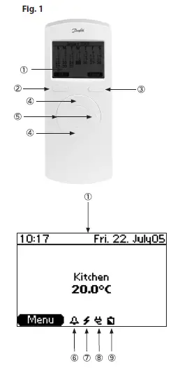
Note: The Remote Controller has a self-explanatory menu structure, and all settings are easily carried out with the up/down and left/right selectors in combination with the functions of the soft keys, which are shown above them in the display.
Back – fig. 2
- Back plate/docking station
- Battery compartment
- Screw hole for wall mounting
- Screw and wall plug
- Transformer/power supply plug
Note: Remove the strip to connect the enclosed batteries. 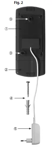
Installation
Note
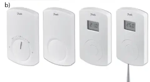
- Install the Remote Controller after you have installed all the Room Thermostats, see fig. 5-b
- Remove the strip to connect the enclosed batteries
- Carry out the assignment of the Remote Controller to the Master Controller within a distance of 1½m
- When the back light in the display is out, the first touch of a button only activates this light
Activate Install mode on the Master Controller – fig. 3
- Use the menu selection button 1 to select the Install mode.
The install LED 2 flashes - Activate Install mode by pressing OK 3 . The install LED 2 goes ON

Activate Install mode on the Remote Controller – fig. 1
- When the batteries have been connected, follow the installation guide, beginning with the selection of language
- After the installation process, set time and date. Use the up/down selector and the left/right selector 5 to carry out the settings. Confirm settings with OK activated by soft key 1 ( 2)
- The installation process is concluded with the opportunity to name the rooms in which the Room Thermostats are placed. This makes access to and handling of the system very easy
- In the Name rooms menu, activate the change menu with soft key 2 ( ) to change the default room names from e.g. MC1 Output 1.2 (Master Controller 1, output 1 and 2) to living room, and confirm with OK.
You can also use the spell…. menu to create other names
When the installation is finished the start up screen will be shown in the display with the actual time and date on the top. The screen also shows the actual temperature in the room from the top of the rooms list. See chapter 5.3 to select another room for the start up screen
Note: Keeping a button activated during settings will make the value change faster
Transmission Test
Initiate a transmission test on the Remote Controller From the start-up screen, activate the:
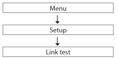
Link test menu to activate a test of the wireless transmission between the Master Controller and the Remote Controller. The status of the link test will be displayed right after the test has been carried through.
If the link test is not successful:
- Try to relocate the Remote Controller in the room
- Or install a Repeater Unit (CF-RU, see fig. 5 c), and place it between the Master Controller and the Remote Controller

Note: The link test may take a few minutes depending on the size of the system
Mounting
The Remote Controller has been installed – fig. 2
When the Remote Controller has been installed to the Master Controller (see chapter 2), it can be mounted on the wall by means of the back plate/docking station 1. This makes it possible to connect the Re-mote Controller to a 230V power supply with the included transformer/power supply plug 5 . When it is not in the docking station, the Remote Controller is powered by two AA Alkaline 1.5V batteries.
- Before you place the back plate/docking station on the wall, verify the trans-mission to the Master Controller from the desired location by carrying out a link test (see chapter 3)
- Mount the back plate/docking station on the wall with the screws and wall plugs 4
- Connect the docking station to a 230V power supply outlet by means of the transformer/power supply plug 5
- Place the Remote Controller in the docking station1
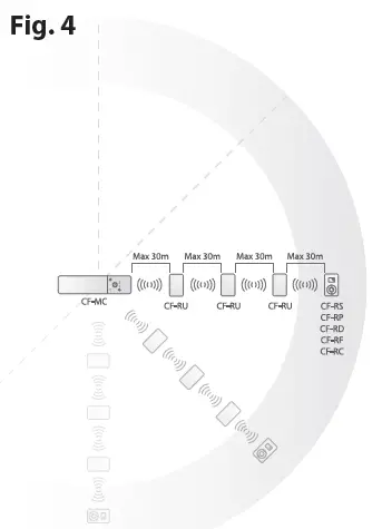
Note: To extend the transmission range of the CF2 system, up to three Repeater Units can be installed in a chain – see fig. 4
 Menus
Menus
Note: When the back light in the display is out, the first touch of a button only activates this light.
Rooms
From the start-up screen, activate the:
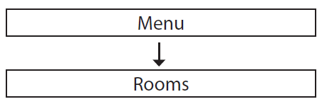
Rooms menu to access a list of all the rooms in the system. Select the desired room with OK to enter the screen for that room. Here you can see information about the set and actual temperatures:
 : Indicates that this room is included in an ongoing time program (see chapter 5.2)
 : Indicates that the Room Thermostat is running low on battery
 : Indicates that the value set on the Room Thermostat is beyond the max./min. limitations set by the Remote Controller
 : Indicates that the set temperature is above the actual temperature
 : Indicates that the set temperature is below the actual temperature
Options
From the room screen, you can activate an Options menu with access to several room options:
Set temperature:
Here you can set and lock the set temperature for the Room Thermostat. Locking prevents adjustment of the set temperature on the Room Thermostat.
Set Min/Max:
Here you can set and lock the minimum and maximum temperatures for the Room Thermostat. Locking prevents adjustment beyond these limits on the Room Thermostat.
Change room name:
Here you can change the room names by means of a list of possible room names or you can use the spell….. menu to key in other names.
Set floor Min/Max:
Here you can set and lock the minimum and maximum floor surface tempera-tures.
Note: Only available with the Room Thermostat with infrared floor sensor, CF-RF
Setback:
Here you can choose to override the next or ongoing setback period (see chapter 5.2.2).
Cooling:
Here you can disable the cooling function for the room in question.
Note: Only available when the Master Controller is in cooling mode
Program
From the start-up screen, activate the:
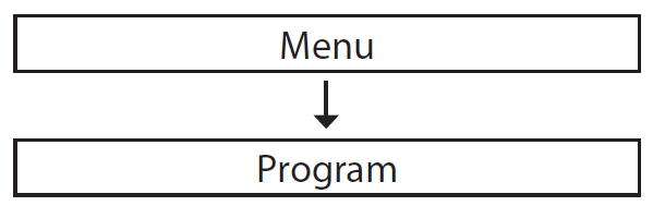
Program menu to view the two time programming options:
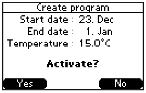
Period program:
With this program, you can set the room temperature for all Room Thermo-stats during e.g. a holiday. The start and end date for the program is easily set in a calendar by means of the up/down and left/right selectors (fig. 1- / ) and by confirming each setting with OK. The room temperature and the duration of the period program are illustrated and finally activated from a detailed overview for the created program:
Setback program:
In the Program setback menu, you have the opportunity to divide the different rooms into up to six different zones – each zone with up to three different setback programs for reduced room temperature at different times during the day.
Options
Each zone has a screen showing the rooms included in the zone. This provides access to an Options menu with an Add room function and three Setback programs (up to).
Add room
In this menu, all the rooms are followed by a ( ) indicating to what zone each room has been allocated (see figure below ). As default, all the rooms are assigned to Zone 1. If new zones are created, the rooms will be moved from the zone to which they are allocated to the new zone (from zone 1 to zone 3 in the figure below).
Program 1 – 3:
The Options menu also includes three possible setback programs for each zone. By means of these, the seven days of the week can be divided into up to three different setback programs with different days and setback periods for each program. The procedure for creating or changing a program is the same for all the three programs:
- Activate program (1- 3) from the Options menu with OK to select the days for GB this program:
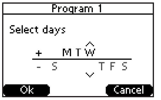
- Use the up/down and left/right selectors (fig. 1- / ) to select the days for this program by moving them above the horizontal line. Confirm with OK, and activate the next step to select the time for the setback program.
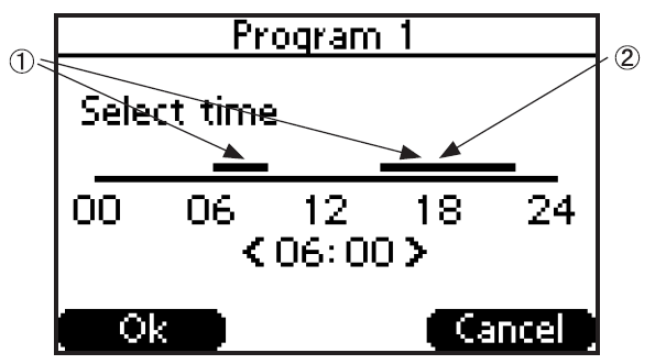
- Select the time for the setback program by setting the times for the periods during which you want a normal room temperature, indicated by the black bars above the time line (the periods outside the black bars are the set-back periods with reduced room temperature). Set the start and end times by means of the left/right selector and by toggling between them using the up/down selector (fig. 1- 4/5 ).
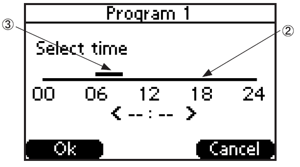
You can remove the second period with the normal room temperature by changing the end time of this period to its start time:
The second period with the nor-mal room temperature 2 can be added again by means of the up/down selector and by toggling through the first period .
Confirm the selected time periods with OK to activate the created program from this overview:
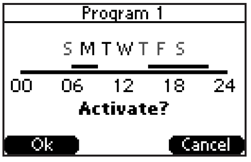
Note: The days selected in the program are indicated by more distinct initial capitals
Cancel program:
A created program can be deleted with the Cancel Program menu leading to the overview illustrated above.
Note:
- In the Options menu, the created programs (1-3) will be indicated by more distinct capitals
- If you want to override a setback period in a room, you can do so with the Override setback function in the Options menu for each room (see chapter 5.1.1)
Setback temperature
In the Setback program (see chapter 5.2.2), activate the Setback temperature menu to set the room temperature reduction from 1 to 10°C during setback periods.
Setup
From the start-up screen, activate the:
Setup menu with access to a variety of information and setting possibilities for the Remote Controller as well as the entire CF2 system.
Note: As some of the setting possibilities in the Setup menu can affect the configuration of the CF2 system, and thus also the functioning of the entire application in general, they should be handled with caution
Languages:
Here you can choose another language than the one selected during the installation process (see chapter 2).
Date and time:
Provides access to the setting of the date and time. Furthermore, this menu includes the settings for and activation of the summertime program. This enables you to configure at what day, week and month the summertime begins and ends.
Alarm:
From this menu, you can switch the Buzzer of the Master Controller (MC) On/Off. The sound only occurs in case of an alarm, also indicated by the red alarm LED on the Master Controller (see fig. 3- ). In the Alarm log, you can get specific information about the error causing the alarm and the time for its registration by the system. This Alarm log saves the latest alarms for later ac-cess and easy system failure identification.
Start-up screen:
Here you can choose which room temperature you want displayed on the start-up screen.
Service:
Here you can configure all the outputs of the Master Controller (see fig. 5-a) for either a floor or radiator heating system. With floor heating, you can choose regulation by means of an On/Off or a PWM (Pulse Width Modulation) principle. Choosing a radiator system automatically sets the regulation to PWM. Even a mixed system with floor and radiator heating in separate rooms can be selected by setting the outputs of the Master Controller individually for each room to either floor or radiator heating.
Note: When the Master Controller is regulated by PWM, the cycle times are:
- Floor heating: 2 hours
- Radiator heating: 15 minutes.
In the Service menu, activate the Standby temperature function with OK in order to set a fixed room temperature for all the Room Thermostats to 5 – 35°C when the Global standby input is activated on the Master Controller (see instruction for Master Controller, CF-MC for installation details).
Contrast:
Here you can adjust the contrast of the Remote Controller display.
Link test:
Activates a link test to the Master Controller to test the wireless transmission to and from the Remote Controller (see chapter 3).
Identify Master Controller:
This function enables you to identify one specific Master Controller in a system of up to three Master Controllers. When this function is activated, the Master Controller, whose identity you wish to reveal, will flash all the output LEDs from 1 to 10 and back again several times for easy identification.
Alarms
If an error occurs in the CF2 system, it is indicated by the Master Controller and directly on the Remote Controller Display:
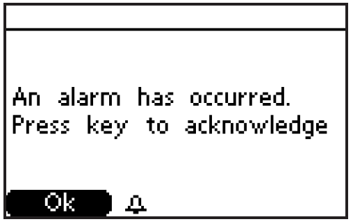
When the alarm is acknowledged with OK, the Buzzer of the Master Controller will go Off (if set to Sound On, see chapter 5.3), and the CF2 system will switch to Alarm status as indicated on the start-up screen: 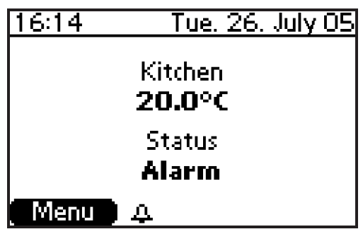
This indication of Alarm on the Remote Controller and the indication on the Master Controller will continue until the error that caused the alarm has been fixed.
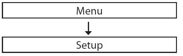
An Alarms menu will be present at the top of the Menu list activated from the start-up screen:
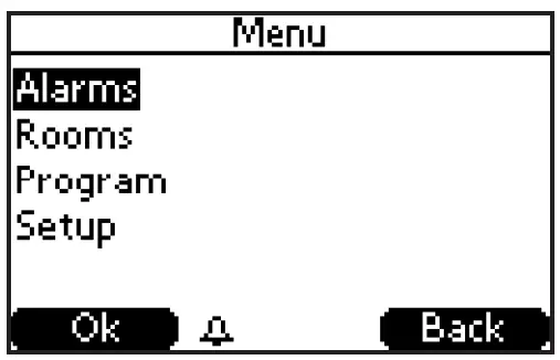
Activating this Alarms menu with OK provides access to an Alarm status where you can see a description of the error causing the alarm Furthermore, you can select the Alarm log to get specific information about the error causing the alarm and the time for its registration by the system. This Alarm log saves the latest alarms for later access and easy system failure identification. When no error is causing an alarm, you can access the Alarm log through the Setup menu (see chapter 5.3).
Uninstallation
Resetting the Remote Controller, CF-RC – fig 1:
- At the same time, activate the Soft key 1 2 , the soft key 2 and the down selector 4 .
- The Remote Controller requests confirmation before resetting. Confirmation with “yes” Resets the Remote Controller.
- By confirming Reset with “yes” the Remote Controller is now ready for installation to a Master Controller, CF-MC.
Note: Please see the Master Controller instruction for further details!
Other products for the CF2 system and abbreviations
Other products for the CF2 system – fig. 5
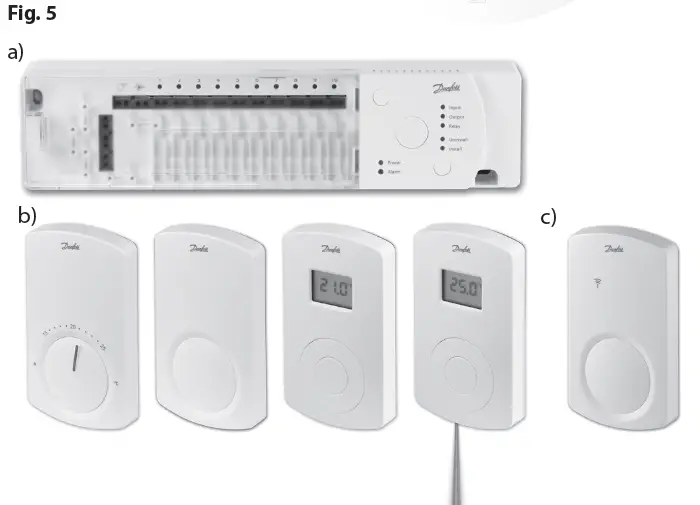
- a) Master Controller, CF-MC: MC
- b) Room Thermostat, CF-RS, -RP, – RD and -RF: Room T.
- c) Repeater Unit, CF-RU: RU
Specifications
| Cable length (power supply) | 1.8m |
| Transmission frequency | 868.42MHz |
| Transmission range in buildings (up to) | 30m |
| Number of Repeater Units in a chain (up to) | 3 |
| Transmission power | < 1mW |
| Supply voltage | 230V a.c. |
| Ambient temperature | 0-50°C |
| IP class | 21 |
Troubleshooting
| Error Indication | Possible Causes |
| Actuator/output (E03) | The output of the Master Controller (MC) or the actuator connected to this output is short-circuited or disconnected. |
| Low temperature (E05) | The temperature in the room is below 5°C. (Try to verify the function of the Room Thermostat by carrying out a link test from it) |
| Link to Master Controller (E12) | The Room Thermostat in the indicated room has lost the wireless connection to the Master Controller (MC) |
| Low bat. in Room T. (E13) | The battery level of the Room Thermostat for the indicated room is low, and the batteries should be replaced |
| Critical bat. in Room T. (E14) | The battery level of the Room Thermostat for the indicated room is critically low, and the batteries should be replaced as soon as possible |
| Link between MCs (E24) | The indicated Master Controllers have lost their wireless connection |
| |
The battery level of the Remote Controller is low, and the batteries should be replaced |
Frequently Asked Questions
- Q: How do I change the batteries in the Remote Controller?
- A: To change the batteries, remove the strip covering the battery compartment and replace with new batteries following the polarity markings.
- Q: How can I troubleshoot connection issues between the Remote Controller and Master Controller?
- A: Refer to the Troubleshooting section in the user manual for specific steps to troubleshoot connection problems.
Documents / Resources
 |
Danfoss CF-RC Remote Controller [pdf] Instructions CF-RC, CF-RC Remote Controller, CF-RC, Remote Controller, Controller |
 |
Danfoss CF-RC Remote Controller [pdf] Instruction Manual VIUHM602, CF-RC Remote Controller, CF-RC, Remote Controller, Controller |


