![]() IPAS manual
IPAS manual
PAS-K02
Apr 2024
(c) Kyungwoo Systech, Inc.
Components

| Name | Model Number | Appearance | Summary |
| PAS2-INDP | PAS-K02-2000 |  |
● You can set the mode, warning distance and display the warning status with the touch LCD. ● Alarm alerts with built-in speakers, LEDs, and LCDs. |
| PAS2-VT | PAS-K02-1000 |  |
● IPAS tag mounted on the equipment. |
| PAS2-EMT | PAS-K02-1500 |  |
● Tags for E Mode |
| PAS2-PT | PAS-K02-0000 |  |
● Tags for pedestrian. |
| PAS2-ZT | PAS-K02-4000 |  |
● Standard Zone tag |
| PAS2-FZT | PAS-K02-5000 |  |
● Zone tag with warning light. |
Hardware specification
2.1. PAS2-INDP
| ITEM | SPECIFICATION | |||||||
| Input Voltage | 12 / 48Vdc | |||||||
| Current consumption | 12V, 500mA(Max) | |||||||
| Processor | Cortex-M7 32bit MCU+FPU STM32F746NEH6, Flash 512KB, RAM 320KB, 168pins, 216MHz |
|||||||
| Sensor | 6-Axis(Gyro + Accelerometer)/ICM-42605(TDK) | |||||||
| MEMORY | SDRAM | 32MB | ||||||
| eMMC | 4GB | |||||||
| Interface | wired | RS-232, CANx2, USB | ||||||
| wireless | Bluetooth v5.0(2.4GHz) | |||||||
| Display | LCD | Touch LCD 3.5” | ||||||
| LED | Visual Alarm | |||||||
| USER INTERFACE | LCD | Touch pannel | ||||||
| External input/output | Switch I/O x 1(Max 2A) DIGITAL INPUT x 1 |
|||||||
| Connector | 1 | ■ Part No. : MB08FBAFF08ST(Female 8 Pins) | ||||||
| Pin No | Pin Name | Pin Type | Description | |||||
| 1 | VBAT | PI | External Voltage(12 ~ 80V) | |||||
| 2 | VBAT | PI | External Voltage(12 ~ 80V) | |||||
| 3 | RS232_TX | DO | RS232 Transmit Data Output | |||||
| 4 | RS232_RX | DI | RS232 Receive Data Input | |||||
| 5 | CAN_L | BI | CAN Low Signal | |||||
| 6 | CAN_H | BI | CAN High Signal | |||||
| 7 | GND | Ground | ||||||
| 8 | GND | Ground | ||||||
| 2 | ■ Part No. : MB08MBAFF08ST(Male 8 Pins) | |||||||
| Pin No | Pin Name | Pin Type | Description | |||||
| 1 | SENPWR_+12V | PO | Output Voltage(12V) | |||||
| 2 | – | – | No Connect | |||||
| 3 | – | – | No Connect | |||||
| 4 | – | – | No Connect | |||||
| 5 | CAN_L | BI | CAN Low Signal | |||||
| 6 | CAN_H | BI | CAN High Signal | |||||
| 7 | GND | Ground | ||||||
| 8 | – | No Connect | ||||||
| 3 | ■ Part No. : MB08MBAFF08ST(Male 8 Pins) | |||||||
| Pin No | Pin Name | Pin Type | Description | |||||
| 1 | EXT_IN | DI | External Input(Max 2A) | |||||
| 2 | EXT_IN | DI | External Input(Max 2A) | |||||
| 3 | D_INPUT | DO | Digital Input | |||||
| 4 | EXT_GND | – | External Ground | |||||
| 5 | EXT_OUT | DO | External Output(Max 2A) | |||||
| 6 | EXT_OUT | DO | External Output(Max 2A) | |||||
| 7 | – | No Connect | ||||||
| 8 | – | No Connect | ||||||
| BT RF Parameter | Frequency / band | 2.4GHz / ISM ( 2.40000 – 2.4835GHz) | ||||||
| Modulation | GFSK | |||||||
| Data rate | 250kbps, 1 Mbps, 2 Mbps | |||||||
| Sensitivity | -97dBm @ 1Mbps Bluetooth LE -103dBm @125kbps Bluetooth LE | |||||||
| Environment | Operating temperature | -20°C ~ +70°C | ||||||
| Storage temperature | -30°C ~ +80°C | |||||||
| Size | 110.0 X 110.0 X 35.2(H) | |||||||
| Color | ORANGE | |||||||
| Ingress Protection Rating | IPX0 | |||||||
2.2 PAS2-VT
| ITEM | SPECIFICATION | |||||
| Input Voltage | 12 / 48Vdc | |||||
| Current consumption | Avr. 100mA@12V Max500mA@12V |
|||||
| Processor | Cortex-M3 32bit MCU, STM32F105RCT6, Flash 256KB, RAM 64KB, 64 Pins, 72MHz | |||||
| Display | Status LED 1set | |||||
| Sensor | 6-Axis(Gyro + Accelerometer, ICM-42605(TDK)) | |||||
| Interface | Wired | CAN | ||||
| Wireless | UWB, BLE | |||||
| UWB RF Parameter | Frequency | 6489.6MHz | ||||
| Bandwidth | 499.2MHz | |||||
| Conducted Rx Sensitivity | -94.3dBm/500MHz (6.8Mbps, PER 1%) | |||||
| Conducted Tx Power Density | Max -41.3dBm/MHz | |||||
| Data rate | 6.8Mbps | |||||
| BT RF Parameter | Frequency / band | 2.4GHz / ISM ( 2.40000 – 2.4835GHz) | ||||
| Data rate | 250kbps, 1 Mbps, 2 Mbps | |||||
| Sensitivity | -97dBm @ 1Mbps Bluetooth LE -103dBm @125kbps Bluetooth LE | |||||
| Connector | 1 | ■ Part No. : MB08MBAFF08ST(Female 8 Pins) | ||||
| Pin No | Pin Name | Pin Type | Description | |||
| 1 | VBAT | PI | External Voltage(12 ~ 80V) | |||
| 2 | VBAT | PI | External Voltage(12 ~ 80V) | |||
| 3 | RS232_TX | DO | RS232 Transmit Data Output(TBD) | |||
| 4 | RS232_RX | DI | RS232 Receive Data Input(TBD) | |||
| 5 | CAN_L | BI | CAN Low Signal | |||
| 6 | CAN_H | BI | CAN High Signal | |||
| 7 | GND | Ground | ||||
| 8 | GND | Ground | ||||
| Environment | Operating temperature | -30°C ~ +65°C | ||||
| Storage temperature | -40°C ~ +85°C | |||||
| Size | 115.5 X 115.5 X 64.5(H) | |||||
| Color | ORANGE+BLACK | |||||
| Ingress Protection Rating | IPX0 | |||||
2.3 PAS2-EMT
| ITEM | SPECIFICATION | |||||
| Input Voltage | 12 / 48Vdc | |||||
| Current consumption | Avr. 100mA@12V | |||||
| Processor | Cortex-M3 32bit MCU, STM32F105RCT6, Flash 256KB, RAM 64KB, 64 Pins, 72MHz | |||||
| Display | Status LED 1set | |||||
| Sensor | 6-Axis(Gyro + Accelerometer, ICM-42605(TDK)) | |||||
| Interface | wire | CAN | ||||
| wireless | UWB | |||||
| UWB RF Parameter | Frequency | 6489.6MHz | ||||
| Bandwidth | 499.2MHz | |||||
| Conducted Rx Sensitivity | -94.3dBm/500MHz (6.8Mbps, PER 1%) | |||||
| Conducted Tx Power Density | Max -41.3dBm/MHz | |||||
| Data rate | 6.8Mbps | |||||
| Connector | ■ Part No. : MB08MBAFF08ST(Female 8 Pins) | |||||
| Pin No | Pin Name | Pin Type | Description | |||
| 1 | VBAT | PI | External Voltage(12 ~ 80V) | |||
| 2 | VBAT | PI | External Voltage(12 ~ 80V) | |||
| 3 | RS232_TX | DO | RS232 Transmit Data Output | |||
| 4 | RS232_RX | DI | RS232 Receive Data Input | |||
| 5 | CAN_L | BI | CAN Low Signal | |||
| 6 | CAN_H | BI | CAN High Signal | |||
| 7 | GND | Ground | ||||
| 8 | GND | Ground | ||||
| Environment | Operating temperature | -30°C ~ +85°C | ||||
| Storage temperature | -40°C ~ +85°C | |||||
| Size | 115.5 X 115.5 X 64.5(H) | |||||
| Color | ORANGE+BLACK | |||||
| Ingress Protection Rating | IPX0 | |||||
2.4 PAS2-PT
| ITEM | SPECIFICATION | |||||
| Power | Input voltage | 4.7 ~ 5.5Vdc | ||||
| Internal Battery | Li-Po Battery 110mAH, 3.8V | |||||
| Current consumption | Avr. 2.2mA | |||||
| Work time | About 35 hour | |||||
| Processor | MCU | Cortex-M4 32bit FPU STM32WB15CCU6E, Flash 320KB, RAM 48KB, 48 Pins, 64MHz |
||||
| Interface | Wired(debug) | UART | ||||
| Wireless | UWB, Bluetooth v5.4(2.4GHz) | |||||
| Display | LED x 4EA (Battery Level, Status Indicator) | |||||
| Sound | 20mm Buzzer Plate | |||||
| Vibration | Cylinder-type vibration motor | |||||
| Button | 1EA(Setup Button) | |||||
| Connector | ■ Part No. : Magnetic Connector | |||||
| Pin No | Pin Name | Pin Type | Description | |||
| 1 | VBAT | PI | External Input Voltage(5V) | |||
| 2 | UART_RX | DI | UART Receive Data Output | |||
| 3 | UART_TX | DO | UART Transmit Data Input | |||
| 4 | GND | – | Ground | |||
| UWB RF Parameter | Frequency | 6489.6MHz | ||||
| Bandwidth | 499.2MHz | |||||
| Conducted Rx Sensitivity | -94.3dBm/500MHz (6.8Mbps, PER 1%) | |||||
| Conducted Tx Power Density | Max -41.3dBm/MHz | |||||
| Data rate | 6.8Mbps | |||||
| BT RF Parameter | Frequency / band | 2.4GHz / ISM ( 2.40000 – 2.4835GHz) | ||||
| standard | RF transceiver supporting Bluetooth® 5.2 specification | |||||
| Data rate | 1Mbps, 2 Mbps | |||||
| Sensitivity | -95.5 dBm (Bluetooth® Low Energy at 1 Mbps | |||||
| Environment | Operating temperature | -20°C ~ +60°C | ||||
| Storage temperature (Battery) | -20°C ~ +45°C (1 months) -10°C ~ +45°C (3 months) 5°C ~ +35°C (recomand) |
|||||
| Design | Size | 41.0 X 41.0 X 13.5(H) | ||||
| Color | BLACK | |||||
| Ingress Protection Rating | IPX0 | |||||
2.5 PAS2-ZT
| ITEM | SPECIFICATION | |||||
| Power | 12/24Vdc | |||||
| Current consumption | Avr. 100mA@12V | |||||
| Processor | Cortex-M3 32bit MCU, STM32F105RCT6, Flash 256KB, RAM 64KB, 64 Pins, 72MHz | |||||
| Display | OLED, 128×32 | |||||
| Sensor | – | |||||
| Interface | Wired | CAN | ||||
| wireless | Bluetooth v5.0(2.4GHz), UWB (6.5GHz) | |||||
| connector | ■ Part No. : MB08FBAFF08ST(Female 8 Pins) | |||||
| Pin No | Pin Name | Pin Type | Description | |||
| 1 | VBAT | PI | Power Input(12/24V) | |||
| 2 | VBAT | PI | Power Input(12/24V) | |||
| 3 | RS232_TX | DO | RS232 Transmit Data Output | |||
| 4 | RS232_RX | DI | RS232 Receive Data Input | |||
| 5 | CAN_L | BI | CAN Low Signal | |||
| 6 | CAN_H | BI | CAN High Signal | |||
| 7 | GND | Ground | ||||
| 8 | GND | Ground | ||||
| UWB RF Parameter | Frequency | 6489.6MHz | ||||
| Bandwidth | 499.2MHz | |||||
| Conducted Rx Sensitivity | -94.3dBm/500MHz (6.8Mbps, PER 1%) | |||||
| Conducted Tx Power Density | Max -41.3dBm/MHz | |||||
| Data rate | 6.8Mbps | |||||
| BT RF Parameter | Frequency / band | 2.4GHz / ISM ( 2.40000 – 2.4835GHz) | ||||
| Data rate | 250kbps, 1 Mbps, 2 Mbps | |||||
| Sensitivity | -97dBm @ 1Mbps Bluetooth LE -103dBm @125kbps Bluetooth LE | |||||
| Environment | Operating temperature | -30°C ~ +85°C | ||||
| Storage temperature | -40°C ~ +85°C | |||||
| Design | size | 110.5 X 111.5 X 91.6(H) | ||||
| color | ORANGE + BLACK | |||||
| Ingress Protection Rating | IPX0 | |||||
2.6 PAS2-FZT
| ITEM | SPECIFICATION | |||||
| Power | 12/24Vdc | |||||
| Current consumption | Max 300mA | |||||
| Processor | Cortex-M3 32bit MCU, STM32F105RCT6, Flash 256KB, RAM 64KB, 64 Pins, 72MHz | |||||
| Display | OLED, 128×32 | |||||
| Sensor | – | |||||
| Interface | Wired | CAN2.0b | ||||
| Wireless | Bluetooth v5.0(2.4GHz), UWB (6.5GHz) | |||||
| Connector | ■ Part No. : MB08FBAFF08ST(Female 8 Pins) | |||||
| Pin No | Pin Name | Pin Type | Description | |||
| 1 | VBAT | PI | Power Input(12/24V) | |||
| 2 | VBAT | PI | Power Input(12/24V) | |||
| 3 | RS232_TX | DO | RS232 Transmit Data Output | |||
| 4 | RS232_RX | DI | RS232 Receive Data Input | |||
| 5 | CAN_L | BI | CAN Low Signal | |||
| 6 | CAN_H | BI | CAN High Signal | |||
| 7 | GND | Ground | ||||
| 8 | GND | Ground | ||||
| UWB RF Parameter | Frequency | 6489.6MHz | ||||
| Bandwidth | 499.2MHz | |||||
| Conducted Rx Sensitivity | -94.3dBm/500MHz (6.8Mbps, PER 1%) | |||||
| Conducted Tx Power Density | Max -41.3dBm/MHz | |||||
| Data rate | 6.8Mbps | |||||
| BT RF Parameter | Frequency / band | 2.4GHz / ISM ( 2.40000 – 2.4835GHz) | ||||
| Data rate | 250kbps, 1 Mbps, 2 Mbps | |||||
| Sensitivity | -97dBm @ 1Mbps Bluetooth LE -103dBm @125kbps Bluetooth LE | |||||
| Environment | Operating temperature | -30°C ~ +85°C | ||||
| Storage temperature | -40°C ~ +85°C | |||||
| Design | Size | 110.5 X 111.5 X 140.6(H) | ||||
| Color | ORANGE + BLACK | |||||
| 방수 | IPX0 | |||||
CABLE SPECIFICATION
3.1 Connector
| ITEM | PART NO | PIN MAP | Appearance | |
| Female (F) | Wire mount | MA08FAHD08STXXCB14 |  |
 |
| Board mount | MB08FBAFF08ST |  |
||
| Male (M) | Wire mount | MA08MAHD08STXXRB14 |  |
 |
| Board mount | MB08MBAFF08ST |  |
||
3.2 Cable specification & Pin map
UL2464 26AWGTS/6C, Jacket:Black PVC,OD:5.0mm
| pin no | color | function |
| 1 | Red | VBATT |
| 2 | Green | VBATT |
| 3 | – | – |
| 4 | – | – |
| 5 | Yellow | CAN L |
| 6 | Blue | CAN H |
| 7 | Black | GND |
| 8 | Orange | GND |
Product Connection Diagram

* VT and EMT are powered from IND.
GUI manual
- Booting
After power on, the boot screen shows as below, then switches to the idle screen.
- Main
The idle screen shows the E-Mode or the S-Mode according to number of VTs.
When another VT or PT is approached, the screen has switched as below.
Enter the main menu when touch the setting icon.
- Setting Menu
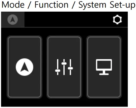
- Mode Selection Menu

- S-Mode Set-up

- E-Mode Set-up

- Additional Function

- System Setting

FCC Compliance Information
This device complies with part 15 of the FCC Rules. Operation is subject to the following two conditions: (1) This device may not cause harmful interference, and (2) this device must accept any interference received, including interference that may cause undesired operation.
This equipment has been tested and found to comply with the limits for a Class B digital device, pursuant to part 15 of the FCC Rules. These limits are designed to provide reasonable protection against harmful interference in a residential installation. This equipment generates, uses and can radiate radio frequency energy and, if not installed and used in accordance with the instructions, may cause harmful interference to radio communications. However, there is no guarantee that interference will not occur in a particular installation. If this equipment does cause harmful interference to radio or television reception, which can be determined by turning the equipment off and on, the user is encouraged to try to correct the interference by one or more of the following measures:
– Reorient or relocate the receiving antenna.
– Increase the separation between the equipment and receiver.
– Connect the equipment into an outlet on a circuit different from that to which the receiver is connected.
– Consult the dealer or an experienced radio/TV technician for help.
Part 15.250(c) Operation on board an aircraft or a satellite is prohibited. Devices operating under this section may not be employed for the operation of toys. Except for operation onboard a ship or a terrestrial transportation vehicle, the use of a fixed outdoor infrastructure is prohibited. A fixed infrastructure includes antennas mounted on outdoor structures, e.g., antennas mounted on the outside of a building or on a telephone pole.
Changes or modifications not expressly approved by the party responsible for compliance could void the user’s authority to operate the equipment.
This device complies with FCC RF exposure requirement.
(c) Kyungwoo Systech, Inc.
Documents / Resources
 |
KYUNGWOO PAS-K02 IPAS 2.0 Design Set [pdf] Instruction Manual PAS-K02, PAS-K02 IPAS 2.0 Design Set, IPAS 2.0 Design Set, Design Set, Set |