JL AUDIO PS-SWMCP Enclosed Speaker Systems

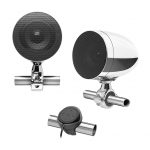
Included Hardware
(hardware pictured for one)
NOTE: The PS-SWMCP-B-SM Fixture and PS650-VeX-SG-TMB Enclosed Speaker System are used in this manual for illustrative purposes only. The fixture installation steps are the same for all PS650-VeX Enclosed Speaker Systems and all PS-SWMCP swivel fixtures for flat surfaces.
For Standard Models:

For Premium Models:

ASSEMBLY STEPS
- Hand-tighten one M6 x 16 mm Socket Cap Machine Screw and Split Lock Washer to temporarily secure the Mounting Base to the Fixture Base of the enclosure, as illustrated.

- Partially thread the M6 x 20 mm Set Screw into the Mounting Receiver. Align the keys of the Mounting Base with the keyways in the Mounting Receiver, then insert fully.

- Place the enclo sure at its desired location with the speaker and Set Screw aimed in the desired direction. L’se a pencil to draw an outline of the Mounting Receiver’s base and location of the Set Screw on the mounting surface. Next, while holding the Mounting Receiver with one hand, rotate and pull the enclosure away to separate it.

- Mark the three mounting hole locations with a pencil, and drill pilot holes on the marks with an appropriate drill bit. Install the Mounting Receiver with three #10 x 1″ Flat Head Phillips Sheet Metal Screws. Insert the Mounting Base into the Mounting Receiver, rotate the enclosure to the desired position, and tighten the Set Screw.

- Determine if the M6 x 20 mm Set Screw is fully recessed into the Mounting Receiver as shown. Loosen the Set Screw, separate the enclosure, and proceed to the appropriate step as noted.

- Slide a Split Lock Washer over each of two M6 x 16 mm Socket Cap Machine Screws, apply Loctite* Red Thread Locking Compound, and fully tighten into the Fixture Base. Repeat for the third fastener. Continue to Step 8.

- Remove the fasteners from Step 1, and rotate the Mounting Base to align with either the next or previous mounting hole in the Fixture Base. Slide a Split Lock Washer over each of three M6 x 16 mm Socket Cap Machine Screws, apply Loctite* Red Thread Locking Compound to the screws, and fully tighten into the Fixture Base.

- Align the keys of the Mounting Base with the keyways in the Mounting Receiver, then in sert fully. Aim the speaker in the desired direction, and tighten the Set Screw in the Mounting Receiver. Remove adhesive backing and install the ]L. Audio logo badge.

- If you wish to rotate the speaker’s grille/logo badge alignment, remove the six #8 x 1-1/4″ speaker mounting screws and #8 Flat Washers.

- Rotate the speaker to the desired angle. Reinstall the speaker and speaker mounting screws and washers. Hand-tighten in a criss-cross pattern.

- Remove the backing from the rear logo appliqué. With the logo positioned at the desired angle, attach the appliqué to the back of the enclo sure.

- Gently press on the appliqué from the center out to remove any air pockets.

- Clean the inside of the aluminum cap with acetone (not included) prior to attaching it to the enclosure. Apply a circular bead of silicone adhesive to the inside of the aluminum logo cap, 1/2-inch (13 mm) from the outer edge.

- Align the aluminum logo cap to the desired angle of rotation, and press it onto the back of the enclosure. Apply masking tape (not included) to hold the cap in place until the silicone cures (at least 24 hours).

- For marine installations, do not connect the speaker’s LED lights to the vessel’s navigational lighting circuits.
- For short-circuit protection, install a supplied fuse holder onto EACH speaker’s BLUE (+12V) LED power connection lead.
- Connect all BLUE (+12V) leads together (parallel) and connect to a switched +12V supply, Connect all YELLOW (GND) leads together and connect to a negative ground or to the NEGATIVE battery post.
- We recommend activating the speakers’ LEDs thru a lighting circuit that supplies +1 2V via an existing switch. If an existing switched circuit is not available, you may install a dedicated toggle/rocker style switch that will supply positive (+12V) power. Fuse this connection according to how many LED circuits you have (LED circuits x 150 mA).

WARRANTY
LIMITED WARRANTY – MARINE PRODUCTS (USA)
JL AUDIO warrants this product to be free of defects in materials and workmanship for a period of two (2) years from the original date of purchase. This warranty is not transferable and applies only to the original purchaser from an authorized JL AUDIO dealer, Should service be necessary under this warranty for any reason due to manufacturing defect or malfunction, IL. AUDIO will (at its discretion), repair or replace the defective product with new or remanufactured product at no charge. Damage caused by the following is not covered under warranty: accident, misuse, abuse, product modification or neglect, failure to follow installation instructions, unauthorized repair attempts, and misrepresentations by the seller. This warranty does not cover incidental or consequential damages and does not cover the cost of removing or reinstalling the unit(s). Cosmetic damage due to accident or normal wear and tear is not covered under warranty. Any applicable implied warranties are limited in duration to the period of the express warranty as provided herein beginning with the date of the original purchase at retail, and no warranties, whether express or implied, shall apply to this product thereafter. Some states do not allow limitations on implied warranties, therefore these exclusions may not apply to you. This warranty gives you specific legal rights, and you may also have other rights which vary from state to state.
CONTACT INFORMATION
- For Service Information in the U.S.A. please call
- JL Audio Customer Service: 954-443-1100
- 9:00 AM – 5:30 PM (Eastern Time Zone)
- JL Audio, Inc
- 10369 North Commerce Pkwy.
- Miramar, FL 33025, USA
- International Warranties:
- Products purchased outside the United States of America are covered only by that country’s distributor and not by JL Audio, Inc.
- www.ilaudio.com
Documents / Resources
 |
JL AUDIO PS-SWMCP Enclosed Speaker Systems [pdf] Installation Guide 106323OM, PS_SWMCP_SM_MAN, PS-SWMCP Enclosed Speaker Systems, PS-SWMCP, Enclosed Speaker Systems, Speaker Systems, Systems |