![]() JAMALERT CELLULAR DETECTION MODULE
JAMALERT CELLULAR DETECTION MODULE
Installation Guide
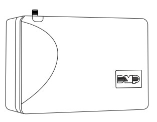 Figure 1: Jam Alert Cellular Detection Module
DESCRIPTION
The JamAlert module is a cellular frequency jamming detector. The module has two onboard outputs that can be connected to zones on a panel or used to trigger peripheral devices. For more information about zone programming, refer to the compatible panel installation guide.
The JamAlert also has an LED to alert when jamming is detected and includes a testing mode to ensure the module is properly detecting frequencies.
What is Included?
▶ One JamAlert Cellular Detection Module
▶ Two 1k Ohm EOL resistors
▶ Four mounting screws
SYSTEM COMPONENTS
Power Connection Terminals
The module may be powered from the 12 VDC auxiliary output of the control panel. Observe polarity and use 18-22 AWG wire to connect the module’s +12 (positive) terminal to the panel’s +12 terminal, and the module’s -12 (negative) terminal to the panel’s -12 terminal. See Figures 2 and 3.
Tamper
The JamAlert module includes a wall and case tamper. The case tamper is pressed when the cover of the module is secured onto the enclosure. The wall tamper is pressed when the back of the cover is mounted onto a wall.
When the cover is removed or the module is removed from the wall, the module sends a tamper trouble message to the monitoring center. 
INSTALLATION
- Select a Location
Install the module away from metal objects and at least 4 to 5 ft. away from any high RF-emitting devices, including high-powered wireless receivers, Wi-Fi routers, and cellular signal boosters, to ensure proper frequency detection. Do not mount the module inside or on a control panel metal enclosure. Mounting the module on or near metal surfaces impairs cellular jamming detection performance. - Mount the Module
The module should be mounted to a wall using the included #6 screws in the mounting holes. See Figure 2. Mount the module in a secure, dry place to protect the module from damage due to tampering or the elements. It is not necessary to remove the PCB when installing the module. - Wire the Module
 Caution: Disconnect all power from the panel before wiring the module. Failure to do so may result in equipment damage or injury. Observe polarity when making power connections.
Use 18 to 22 gauge wire when wiring the module. When routing wires, ensure they do not interfere with the tamper switch. Refer to Figures 3 and 4.
1. Use a wire to connect the module’s 12V positive to terminal 7 on the DMP panel. Use another wire to connect the module’s 12V negative to terminal 10 on the DMP panel.
 Note: If you are connecting to a non-DMP panel, confirm the proper terminals for the positive and negative 12V.
2. On the cell jamming detection output, use a wire to connect the NO terminal to any zone on the panel. Use another wire to connect the C terminal to the panel ground.
Note: If you are connecting to a DMP panel, use a 1k Ohm EOL resistor across the NO and C terminals. If connecting to a non-DMP panel, use the correct resistance value for that panel.
3. On the tamper output, use a wire to connect the C terminal to any zone on the panel. Use another wire to connect the NC terminal to the panel ground. Use a 1k Ohm EOL resistor on the wire connected to the NC terminal.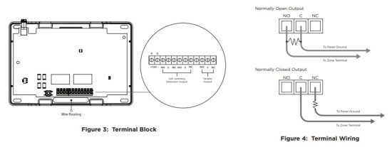
- Connect the Antenna
1. Place the antenna onto the SMA connector. Refer to Figure 2.
2. Twist the antenna until it is securely tightened.
3. Carefully replace the housing cover on the mounted base. Ensure not to damage any PCB components when removing or replacing the housing cover.
PROGRAM THE PANEL
Refer to the compatible panel programming guide for full programming information. After completing each step, press CMD to advance to the next prompt. To program the JamAlert to a DMP panel, complete the following steps:
- Reset the panel. At a keypad, enter 6653 (PROG) to access the PROGRAMMER menu.
- At ZONE INFORMATION, enter the zone number for the cell jamming detection output.
- At *UNUSED*, enter a name for the zone.
- Select a ZONE TYPE.
- At NEXT ZONE, select YES.
- Enter the zone number for the tamper output
- At *UNUSED*, enter a name for the zone.
- Select a ZONE TYPE.
- Press CMD until STOP displays. Press a top row select key or area to save programming.
ADDITIONAL INFORMATION
Module Operation
When cell frequency jamming is detected, the onboard output is activated and sends an alarm to the panel. In addition, if cell jamming is detected, the LED lights red. If power is on, the LED lights green.
Testing Mode
JamAlert uses a local testing operation to ensure the module is properly detecting frequencies. To enter testing mode, complete the following steps:
- Ensure the JamAlert is in its housing and the back case tamper is satisfied.
- Disconnect the antenna, then power on the JamAlert.
- Press the tamper button at least 4 times in a row quickly to enter testing mode.
- Connect the antenna to automatically trigger the detection mode. When the device detects a frequency, the LED turns on.
- To exit testing mode, power cycle the device or press and hold the tamper button for more than 5 seconds. The LED flashes green 3 times to confirm you have exited testing mode.
Compatibility
▶ XTL Series Control Panels
▶ XT Series Control Panels
▶ XF6 Series Control Panels
▶ XR Series Control Panels
▶ TMSentry Control Panels
▶ Com Series Communicators
Ordering Information
JAMALERT Cellular Jamming Detection Module
Specifications
Primary Power 12 VDC from panel
Current Draw
Standby (Tamper On) 131 mA
Alarm (Jammed, Tamper On) 206 mA
![]() Designed, engineered, and
Designed, engineered, and
manufactured in Springfield, MO
using U.S. and global components.
LT-2962 25192
© 2025
INTRUSION • FIRE • ACCESS • NETWORKS
2500 North Partnership Boulevard
Springfield, Missouri 65803-8877
800.641.4282 | DMP.com
Documents / Resources
 |
JamAlert LT-2962 Cellular Detection Module [pdf] Installation Guide LT-2962 Cellular Detection Module, LT-2962, Cellular Detection Module, Detection Module, Module |