![]() SHENZHEN INVT ELECTRIC CO., LTD.
SHENZHEN INVT ELECTRIC CO., LTD.
EC-TX809-U5 Industrial
Ethernet Communication Module
User Manual
EC-TX809-U5 Industrial Ethernet Communication Module
Preface
Thank you for choosing INVT EC-TX809-U5 industrial Ethernet communication module.
The EC-TX809-U5 is an industrial Ethernet communication module that supports multiple protocols and is designed to be integrated into GD880 series VFD control box, enabling communication with Ethernet master stations across various protocols.
This manual provides the product overview, installation, wiring, and commissioning instructions. To ensure safe and proper use of the product and to maximize its performance, please carefully read the manual before installation.
Product features
- Supports protocol selection through function codes.
- Supports up to five protocols, including PROFINET I/O, EtherCAT, EtherNet IP, Modbus TCP, and PowerLink communication protocols.
- Equipped with two RJ45 ports.
- Reaches the communication rate of up to 100 Mbit/s, with a short communication cycle.
- Supports both linear and star network topologies, with certain protocols also accommodating ring network topology.
Product overview
1.1 Product nameplate and model 1.2 Specifications
| Parameter | Specifications |
| Working temperature | -10-+50°C |
| Storage temperature | -20-+60°C |
| Relative humidity | 5%-95% (No condensation) |
| Running environment | No corrosive gas |
| Mounting method | Fixed with snap-fits and screws |
| Ingress protection (IP) rating | IP20 |
| Cooling method | Natural air cooling |
| Communication rate | 100M bit/s |
| Network topology | Supports both linear and star network topologies, with certain protocols also accommodating ring network topology. |
1.3 Structure
 Table 1-1 Product component description
| No. | Name | Description |
| 1 | STATUS bus status indicator (green) | For details about each protocol, see 1.4 Indicator. |
| 2 | FAULT fault indicator (Red) | For details about each protocol, see 1.4 Indicator. |
| 3 | Installation fixing hole | Helps to secure the communication module and ensure a good PE layer connection. |
| 4 | X1 communication network port | Communication interface 1 (IN). |
| 5 | X2 communication network port | Communication interface 2 (OUT). |
| 6 | Programming configuration port | Connects to the host controller through USB Type-C. |
| 7 | Nameplate | Contains communication module model and serial number information. |
| 8 | Connection port | For electrical connection with the control box. |
| 9 | Positioning hole | Helps to align the communication module and control box for easy installation. |
1.4 Indicator
Table 1-2 PROFINET communication indicators
| Indicator | Color | Definition | Function |
| LED1(STATUS) | Green | Steady on | Communication established successfully, with normal 10 data exchange. |
| Blinking (on for 500ms, off for 500ms) | Communication established successfully, but without valid 10 data exchange. | ||
| Blinking (on for 100ms, off for 100ms) | In the communication configuration phase. For example, when DCP configuration commands are triggered, it will blink simultaneously with the FAULT indicator. | ||
| Steady off | The communication between the communication card and PLC is not in Online state. | ||
| LED2(FAULT) | Red | Steady off | No fault |
| Blinking (on for 100ms, off for 100ms) | Communication establishment is abnormal. |
Table 1-3 EtherCAT communication indicators
| Indicator | Color | Definition | Function |
| LED1(STATUS) | Green | Steady off | In ‘nit state. |
| Blinking (on for 200ms, off for 200ms) | In PreOP state. | ||
| Single flash (on for 200ms, off for 1s) | In SafeOP state. | ||
| Steady on | In OP state. | ||
| LED2(FAULT) | Red | Steady off | No fault |
| Blinking (on for 200ms, off for 200ms) | The Init/PreOP fault occurred. | ||
| Single flash (on for 200ms, off for 1s) | The SafeOP fault occurred. | ||
| Steady on | The OP fault occurred. |
Table 1-4 PowerLink communication indicators
| Indicator | Color | Definition | Function |
| LED1(STATUS) | Green | Steady off | In ‘nit state. |
| Blinking (on for 50ms, off for 50ms) |
In NMT CS BASIC ETHERNET state. | ||
| Single flash (on for 500ms, off for 500ms) |
In WIT CS PRE_OPERATIONAL1 state. | ||
| Double flashes (on for 250ms, off for 250ms) |
In NMT_CS_PRE_OPERATIONAL_2 state. | ||
| Triple flashes (on for 125ms, off for 125ms) |
In NMT_CS_READY_TO_OPERATE state | ||
| Steady on | In NMT_CS_OPERATIONAL state | ||
| Blinking (on for 200ms, off for 200ms) |
In NMT_CS_STOPPED state | ||
| LED2(FAULT) | Red | Steady off | No fault |
| Steady on | Data frame lost, communication disconnected, or NMT internal critical error (such as illegal interruption and memory overrun). |
Table 1-5 EtherNet IP communication indicators
| Indicator | Color | Definition | Function |
| LED1(STATUS) | Green | Steady on | The communication between the communication card and the PLC is online, and data exchange is allowed. |
| Blinking (on for 500ms, off for 500ms) |
Abnormal setting of the IP address for either the communication card or the PLC. | ||
| Steady off | The communication between the communication card and PLC is not in Online state. |
||
| LED2(FAULT) | Red | Steady off | No fault |
| Blinking (on for 500ms, off for 500ms) |
Incorrect PLC configuration. | ||
| Blinking (on for 250nns, off for 250ms) |
The communication card failed to send data to the PLC. | ||
| Blinking (on for 125ms, off for 125ms) |
The connection between the communication card and PLC timed out. |
||
| Steady on | Failed to set up data communication between the communication card and PLC. |
Table 1-6 Modbus TCP communication indicators
| Indicator | Color | Definition | Function |
| LED1(STATUS) | Green | Steady on | The communication between the communication card and the PLC is online, and data exchange is allowed. |
| Blinking (on for 500ms, off for 500ms) |
Abnormal setting of the IP address for either the communication card or the PLC. | ||
| Steady off | The communication between the communication card and PLC is not in Online state. | ||
| LED2(FAULT) | Red | Steady on | The communication card and PLC are in Offline state. |
| Blinking (on for 500ms, off for 500ms) |
Unsupported CMD control word command or PR function code value. | ||
| Blinking (on for 62.5ms, off for 62.5ms) |
Non-existent node address. | ||
| Steady off | The connection between the communication card and PLC is normal. |
1.5 Communication protocol selection
Table 1-7 Communication protocol selection
| Function code | Communication protocol | Default |
| P7.83-P7.91 | PROFINET | Factory setting (0) |
| EtherCAT | 1 | |
| PowerLink | 2 | |
| EtherNet IP | 3 | |
| Modbus TCP | 4 |
1.6 Protocol parameter
Table 1-8 Protocol parameter description
| Function code | Communication protocol | Description |
| P7.83— P7 91 |
PROFINET | • Supports the PROFINET protocol, accommodating PROFINET 10 devices, medium redundancy protocol (MRP), and system redundancy protocol (S2). Equipped with the slave station GSDML configuration file, it can communicate with Siemens PLC and other master stations. • Enables basic operations on VFDs, such as reading and writing process values, reading status values, and reading/writing function codes. This communication card supports up to 3210s. • Applicable to linear, star, and ring network topologies. |
| EtherCAT | • Configured with a slave XML configuration file, communication between the master stations (such as Beckhoff PLCs and INVT controllers) and the VFD can be established. It supports up to 32 bytes of I/O data exchange but does not support CiA301 or CiA402 EoE protocols. • Supports PDO services and manufacturer-defined object dictionaries, meeting the EtherCAT compliance testing certification requirements within the factory. • Applicable to linear, star, and ring network topologies. • Equipped with two RJ45 ports, designated for IN and OUT directions. |
|
| PowerLink | • Configured with a slave station XDD configuration file, communication between master stations (such as B&R PLCs) and the VFD can be established. The CiA401 protocol is not supported. • Supports PDO services and manufacturer-defined object dictionaries for communication with the VFD • Applicable to linear and star network topologies. |
|
| EtherNet IP | • Supports ODVA standards and DLR ring protocol. When configured with a slave station EDS configuration file, it can communicate with Rockwell PLC and other master stations. • Enables basic operations on VFDs, such as reading and writing process values, reading status values, and reading/writing function codes. This communication card supports up to 3210s. • Applicable to linear, star, and ring network topologies. |
|
| Modbus TCP | • Supports the Modbus TCP protocol. A Modbus TCP slave station can communicate with multiple master stations simultaneously. It can communicate with Schneider PLC, INVT controllers, and other master stations. • Enables basic operations on VFDs, such as reading and writing process values, reading status values, and reading/writing function codes. • Applicable to linear and star network topologies. |
![]() Note: After each change to P7.8-P7.91, the expansion card will automatically reset and complete the protocol switchover. It will take some time to re-establish communication with the PLC using the new protocol. If a communication timeout fault occurs on the VFD during this period, you can clear it by pressing the reset key on the keypad.
Note: After each change to P7.8-P7.91, the expansion card will automatically reset and complete the protocol switchover. It will take some time to re-establish communication with the PLC using the new protocol. If a communication timeout fault occurs on the VFD during this period, you can clear it by pressing the reset key on the keypad.
Installation and wiring
2.1 Installation precautions
| Make sure the device have been powered off before installation. | |
| Note | • There are three expansion card interfaces (slot 1, slot 2, and slot 3) on the control box. You can use any of these slots based on the actual wiring requirements. • The EC-TX809-U5 industrial Ethernet communication module is recommended to be installed in slot 3. |
Tools required for installation: Phillips screwdriver PH1; slotted screwdriver SL3.
Table 2-1 Screw torque requirements
| Screw requirements | Fastening torque |
| M3 | 0.55 Nm |
2.2 Dimensions
EC-TX809-U5 dimensions are 73.5×74×23.3mm (WXHXD). See Figure 2-1. 2.3 Installation instructions
EC-TX809-U5 is recommended to be installed in slot 3 of the control box. The following describes the installation procedure using slot 3 as an example.
Step 1 Position the communication module in the designated area of slot 3 on the control box, ensuring proper alignment with the slot before securely fastening it together.
Step 2 Guide the communication module into place using the positioning stud.
Step 3 Secure it in position with M3 screws, completing the installation.
![]() Note:
Note:
- The communication module and control box are electrically connected through a slot. Please install them in place..
- To ensure the reliable operation of the communication module and EMC requirements are met, please tighten the screws according to the recommended torque for reliable grounding.
2.4 Disassembly instructions
You can disassembly the product by reversing the order of steps described in section 2.3. Installation instructions.
Step 1 Disconnect the power supply and disassemble all cables connected to the expansion module.
Step 2 Use a Phillips screwdriver to remove the grounding screw of the module.
Step 3 Pull the expansion module out to a suitable position.
2.5 User’s wiring terminals
 Table 2-2 RJ45 terminal functions
| X1-X2 terminals | Pin no. | Definition | Description |
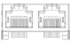 |
1, 9 | TX+ | Transmit Data+ |
| 2,10 | TX- | Transmit Data- | |
| 3,11 | RX+ | Receive Data+ | |
| 4,12 | n/c | Not connected | |
| 5,13 | n/c | Not connected | |
| 6,14 | RX- | Receive Data- | |
| 7,15 | n/c | Not connected | |
| 8,16 | n/c | Not connected |
2.6 Wiring precautions
The communication card uses standard RJ45 interfaces, and its electrical connections are shown in Figure 2-3, Figure 2-4, and Figure 2-5.
![]() Note: It is recommended to use double-twisted shielded Category 5e Ethernet cables, with crystal heads equipped with iron shells to meet the grounding shield protection.
Note: It is recommended to use double-twisted shielded Category 5e Ethernet cables, with crystal heads equipped with iron shells to meet the grounding shield protection.
![]() Note: For the star network topology, you need to prepare switches.
Note: For the star network topology, you need to prepare switches.
Commissioning

Table 3-1 EC-TX809-US related function code settings
| Function code | Name | Parameter description | Setting range | Default | Remarks |
| P37.00 P37.02- P37.13 |
Sent PZD1- PZD12 source |
0: 0 1:Digital (0-65535, 0) 2:Other-C connector (0.00-99.99, 20.34) 3:All 4:Al2 5:HDI1 6:HDI2 7:Multi-step running 8:MOP |
0-8 | 2 | Slave-to- master data source |
| P37.62- P37.77 |
Sent PKW1- PZD12 data display |
Sent PKW1-PKW4 data display Sent PZD1-PZD12 data display |
0x0000- OxFFFF |
0x0000 | Slave-to- master data display |
| P37.78- P37.93 |
P37.78- Received PKW1- data display |
Received PKW1-PKW4 data display Received PZD1-PZD12 data display |
Ox0000- OxFFFF |
Ox0000 | Master-to- slave data display |
| P38.00 | Matching bus type of bus adapter |
0: None 1:PROFIBUS-DP module 2:PROFINET 10 module 3:CANopen module 4:EtherNet IP module 5:EtherCAT module 6:PowerLink module 7:216 communication card module |
0-7 | 2 | – |
| P38.02- P38.13 |
Sent PZD1- PZD12 source |
0: 0 1:Digital (0-65535, 0) 2:Other-C connector (0.00-99.99, 20.34) 3:All 4:Al2 5:HDI1 6:HDI2 7:Multi-step running 8:MOP |
0-8 | 2 | Slave-to- master data source |
| P38.62- P38.77 |
Sent PKW1- PZD12 data display |
Sent PKW1-PKW4 data display Sent PZD1-PZD12 data display |
0x0000- OxFFFF |
Ox0000 | Slave-to- master data display |
| P38.78- P38.93 |
P38.78- Received PKW1- PZD12 data display |
Received PKW1-PKW4 display Received PZD1-PZD12 data display |
Ox0000- OxFFFF |
Ox0000 | Master-to- slave data display |
| P42.14- P42.25 |
Industrial Ethernet communication card IP |
Industrial Ethernet communication card IPaddress, subnet mask, and gateway | 0-255 | – | Modbus TCP, EtherNet/IP |
| P41.00 | Module online state |
Bit0-bit8 EC slot module online state (0: Offline; 1: Online) |
0-1 | 0 | PROFINET 10 |
| P45.03 | Module online state |
Bit0-bit8 EC slot module online state (0: Offline; 1: Online) |
0-1 | 0 | EtherCAT |
| P45.04 | EtherCAT station no. |
Slave station no. setting. | 0-65535 | 1 | |
| P45.06 | Module online state |
Bit0-bit8 EC slot module online state (0: Offline; 1: Online) |
0-1 | 0 | PowerLink |
| P45.08 | PowerLink station no. |
Slave station no. setting. | 1-256 | 1 | |
| P45.00 | Module online state |
BitO-bit8 EC slot module online state (0: Offline; 1: Online) |
0-1 | 0 | Select adapter A for EtherNet/IP |
| P42.11 | Module online state |
Bit0-bit8 EC slot module online state (0: Offline; 1: Online) |
0-1 | 0 | Modbus TCP |
| P42.00 | Local Modbus address |
Slave address | 1-247 | 1 |
![]() Note:
Note:
- When two identical expansion modules are inserted into a VFD simultaneously, only the module in the slot with a smaller number will be active, while the module in the slot with a larger number will be redundant. For example, if two PROFINET expansion modules are inserted into slot 1 and slot 2, the PROFINET module in slot 1 will be active.
- For additional parameter settings for EC-TX809-U5, see the GD880 series product software manuals.
![]()
 Copyright©INVT.
Manual information may be subject
to change without prior notice.
Documents / Resources
 |
INVT EC-TX809-U5 Industrial Ethernet Communication Module [pdf] User Manual TX809-U5, EC-TX809-U5 Industrial Ethernet Communication Module, EC-TX809-U5, Industrial Ethernet Communication Module, Ethernet Communication Module, Communication Module, Module |