intelbras PSR450 Power Module
Overview
PSR450 power module series include PSR450-12A, PSR450-12A1, PSR450-12AHD, and PSR450-12D. The PSR450-12A, PSR450-12A1, and PSR450-12AHD power modules support AC and high-voltage DC inputs, and the PSR450-12AHD supports 240V/336V high-voltage DC input. The PSR450-12D supports DC input. They can provide a maximum output of 450 W. The PSR450-12A provides power module-side intake and port-side exhaust airflows. The PSR450-12A1, PSR450-12AHD, and PSR450-12D provides port-side intake and power module-side exhaust airflows.
The power modules provide the following features:
- Self-protection—The power modules provide output overvoltage, output current limiting, output short circuit, overtemperature, and input undervoltage protections. See the following table for the protection and auto-recovery features of the power Rated input current modules.
- Redundancy—Two power modules can be connected in parallel to achieve 1+1 redundancy and load sharing.
- Hot swapping—You can remove one of the two power modules in 1+1 redundancy while the device is operating.
| Protection function | Protection state | Support for auto-recovery |
| Output overvoltage protection | The power module does not supply power, and the power module status LED is steady red | No. Power supply can restore only when you reconnect the power cord to the power source |
| Output current limiting protection | The power module does not supply power, and the power module status LED is steady red. | Power supply restores after the output current decreases to an acceptable range. |
| Output short circuit protection | The power module does not supply power, and the power module status LED is steady red. | Power supply restores after the output current decreases to an acceptable range. |
| Overtemperature protection | The power module does not supply power, and the power module status LED is steady red | Power supply restores after the output current decreases to an acceptable range. |
| Input undervoltage protection | The power module does not supply power, and the power module status LED is flashing red. | Power supply restores after the output current decreases to an acceptable range. |
Technical Specifications
Whether the power module supports high-voltage DC input depends on the device model. For information, see hardware information and specifications for the device.
| Item | Specifications | ||
| PSR450-12A/PSR450- 12A1 | PSR450-12AHD | ||
| AC input | Rated input voltage | 100 to 240 VAC @ 50 or 60 Hz | 100 to 240 VAC @ 50 or 60 Hz |
| Rated input current | 6 A | 6 A | |
| Max input voltage | 90 to 290 VAC @ 47 to 63 Hz |
90 to 290 VAC @ 47 to 63 Hz |
|
| Max input current | 7 A | 7 A | |
| High-voltage DC input | Rated input voltage | 240 VDC | 240 to 380 VDC |
| Rated input current | 3 A | 3 A | |
| Max input voltage | 180 to 320 VDC | 180 to 400 VDC | |
| Max input current | 3.5 A | 3.5 A | |
| Output voltage | 12 V/3.3 V | 12 V/3.3 V | |
| Output current | 37.5 A (12 V)/2 A (3.3 V) | 37.5 A (12 V)/2 A (3.3 V) | |
| Max output power | 450 W | 450 W | |
| Dimensions (H × W × D) | 40.2 × 50.5 × 221 mm (1.58 × 1.99 × 8.70 in) |
40.2 × 50.5 × 221 mm 1.58 × 1.99 × 8.70 in) |
|
| Operating temperature | –10°C to +55°C (14°F to 131°F) | –10°C to +55°C (14°F to 131°F) | |
| Relative humidity | 5% to 95% | 5% to 95% | |
| AC input | Rated input voltage | 48 to -60 VDC | |
| Rated input current | 12 A (48 VDC) 10 A (60 VDC) |
||
| Max input voltage | -36 to -72 VDC | ||
| Max input current | 15 A | ||
| Output voltage | 12 V/3.3 V | ||
| Output current | 37.5 A (12 V)/2 A (3.3 V) | ||
| Max output power | 450 W | ||
| Dimensions (H × W × D) | 40.2 × 50.5 × 221 mm (1.58 × 1.99 × 8.70 in) | ||
| Operating temperature | –10°C to +55°C (14°F to 131°F) | ||
| Relative humidity | 5% to 95% | ||
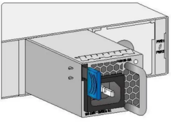
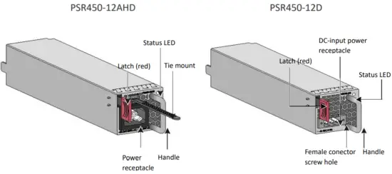
Views
A blue latch indicates power module-side intake and port-side exhaust airflows. A red latch indicates port-side intake and power module-side exhaust airflows.

LEDs
The power module has a status LED on its front panel.
The following table provides the LED description.
| LED status | Description |
| Steady green | The power module is operating correctly. |
| Flashing green | The power module has power input but is not installed in the device. |
| Steady red | |
| Red/Green flashing alternatively | The power module has generated an alarm for power problems (such as output overcurrent, output overload, and overtemperature), but has not entered protection state. |
| Flashing red |
|
| Off | The power module does not have power input. |
Safety guidelines
To prevent device damage and bodily injury, follow these restrictions and guidelines when you install or remove the power module:
- Before you install a power module, make sure its airflow direction is as required.
- Do not install power modules that provide different airflow directions on the same device.
- Always wear an ESD wrist strap and make sure it makes good skin contact.
- Before installing a power module, make sure the voltage of the power source is as required by the power module, and the output voltage of the power module is as required by the device.
- Do not touch any bare cables or terminals.
- Do not place the power module in a wet area, and prevent liquid from flowing into the power module.
- To avoid power module damage, do not open the power module. When the internal circuits or components of the power module fail, contact Intelbras Support
Tools
No ESD wrist strap is provided with the power module. Prepare it yourself.
Installing and removing the power module
- The installation and removal procedures for the PSR450 power modules are similar. The following procedures use a PSR450-12A power module as an example
- Make sure the power module is compatible with the device. For information about the compatibility matrix between power modules and the device, see the installation guide for the device.
Installing the power module
To avoid bodily injury or device damage, follow the steps in the following figure to install the power module.

- Wear an anti-static wrist strap, make sure that the anti-static wrist strap is in good contact with the skin, and confirm that the anti-static wrist strap is well grounded.
- Remove the filler panel, if any, from the target power module slot. Keep the removed filler panel secure for future use.
- Unpack the power module and verify that the power module model is as required. Keep the power Module package secure for future use.
- Correctly orient the power module. Holding the power module handle with one hand and supporting the power module bottom with the other, slide the power module along the guide rails into the slot until you hear a click.

- Make sure the power module makes good contact with the backplane of the device.
- The power module slot has a disorientation rejection structure. If you cannot insert the power module into the slot, re-orient the power module rather than use excessive force to push it in.
Connecting the power cord
- Make sure each power cord has a separate circuit breaker.
- Turn off the circuit breaker before connecting the power cord.
- For a PSR450-12D power module, the power cord connector and the receptacle form a disorientation rejection structure. If you cannot insert the connector into the receptacle, the orientation might be wrong. Re-orient the connector rather than use excessive force to push it in.
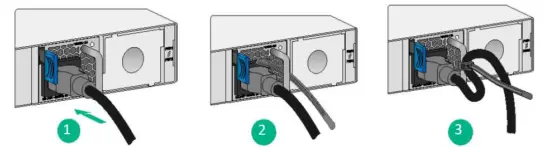
- Connect and secure the power cord to the power module
PSR450-12A/PSR450-12A1 power module
For a PSR450-12A or PSR450-12A1 power module, connect the female connector of the power cord to the power receptacle on the power module, and then use a cable tie to secure the power cord to the handle of the power module.
PSR450-12AHD power module PSR450-12AHD
For a PSR450-12AHD power module, slide the cable clamp onto the tie mount, connect the female connector of the power cord to the power receptacle on the power module, and then close the cable clamp and slide it forward until it is flush against the edge of the female connector.
PSR450-12D power module PSR450-12D
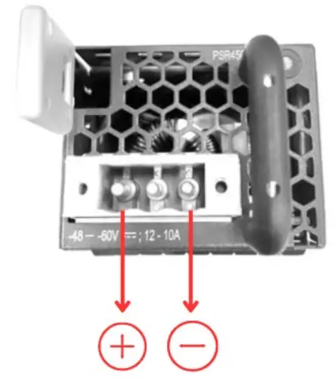
For a PSR450-12D power module, use a flat-head screwdriver to loosen the screws on the protection cover over the power receptacle and then remove the cover. Connect the female connector of the power cord to the power receptacle on the power module, and then fasten the screws on the connector.
- To prevent the power cord from falling off, use a removable cable tie to secure the power cord to the power module handle. For the securing method, see “PSR450-12A/PSR450-12A1 power module.”
- Connect the other end of the power cord to an AC or DC power source, and then turn on the circuit breaker.
- Examine the LED on the power module. If the LED is steady green, the power cord is connected correctly. If the LED is off or red, examine the installation and troubleshoot the problems until the LED becomes steady
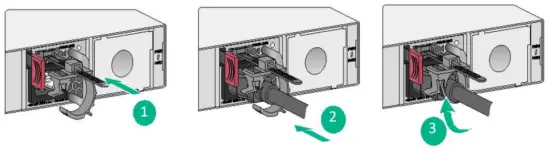
Removing the power module
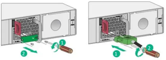
To avoid bodily injury or device damage, follow the steps in the following figure to remove the power module.

- Turn off the circuit breaker for the power feed to the power module.
- Wear an ESD wrist strap, and make sure the strap makes good skin contact and is reliably grounded.
- Loosen the removable cable tie, and remove the power cord connector from the power module.

- For a PSR450-12D power module, use a flat-head screwdriver to loosen the screws on the connector, and then remove the power cord connector from the power module.
For a PSR450-12AHD power module, release the jaw of the cable clamp and open the cable clamp, and then remove the power cord connector from the power module.

- Put the removed power module on an antistatic mat or in its initial package.

If you are not to install a power module in the slot, install a filler panel in the slot to prevent dust from entering the chassis.
Box content: 1 x power supply, 1 x 2 meters Brazil standard power cable
Compatible with: SC 5525 Series, SC 5530 Series.

Documents / Resources
 |
intelbras PSR450 Power Module [pdf] User Manual PSR450, PSR450 Power Module, Power Module, Module |


