Intel E-Series 5 GTS Transceiver
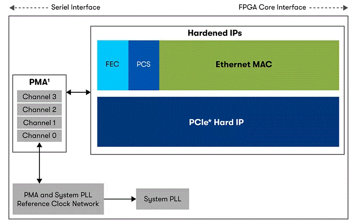
Specifications
- Product Name: GTS Transceiver Dual Simplex Interfaces
- Model Number: 825853
- Release Date: 2025.01.24
Product Information
The GTS transceivers in Agilex 5 FPGAs support various simplex protocol implementations. In simplex mode, the GTS channel is unidirectional, leaving an unused transmitter or receiver. By using the dual simplex mode, you can utilize the unused channel to implement another independent simplex protocol.
Introduction
This user guide describes the method to implement the dual simplex (DS) mode in Agilex™ 5 GTS transceivers.
The dual simplex mode refers to the operating mode of the GTS transceiver channel where you can place an independent transmitter and an independent receiver in the same transceiver channel, thereby maximizing the transceiver resource utilization in Agilex 5 FPGAs. The user guide describes:
- Supported simplex protocol IPs in dual simplex mode
- How to plan for dual simplex interfaces prior to starting your design
- How to implement the dual simplex design flow
You can implement the dual simplex mode in Quartus® Prime Pro Edition software version 24.2 onwards.
Related Information
- GTS Transceiver PHY User Guide
- GTS SDI II Intel FPGA IP User Guide
- GTS SDI II Intel FPGA IP Design Example User Guide
- GTS HDMI Intel FPGA IP User Guide
- GTS HDMI Intel FPGA IP Design Example User Guide
- GTS DisplayPort PHY Altera FPGA IP User Guide
- GTS JESD204C Intel FPGA IP User Guide
- GTS JESD204C Intel FPGA IP Design Example User Guide
- GTS JESD204B Intel FPGA IP User Guide
- GTS JESD204B Intel FPGA IP Design Example User Guide
- GTS Serial Lite IV Intel FPGA IP User Guide
- GTS Serial Lite IV Intel FPGA IP Design Example User Guide
- Quartus Prime Pro Edition User Guide: Design Compilation
© Altera Corporation. Altera, the Altera logo, the ‘a’ logo, and other Altera marks are trademarks of Altera Corporation. Altera and Intel warrant performance of its FPGA and semiconductor products to current specifications in accordance with Altera’s or Intel’s standard warranty as applicable, but reserves the right to make changes to any products and services at any time without notice. Altera and Intel assume no responsibility or liability arising out of the application or use of any information, product, or service described herein except as expressly agreed to inwriting by Altera or Intel. Altera and Intel customers are advised to obtain the latest version of device specifications before relying on any published information and before placing orders for products or services.
Other names and brands may be claimed as the property of others.
Overview
The GTS transceivers in Agilex 5 FPGAs support various simplex protocol implementations. In simplex mode, the GTS channel is unidirectional and that leaves an unused transmitter or receiver. Using the dual simplex mode, you can utilize the unused transmitter or receiver channel to implement another independent simplex protocol as shown in the following figure.

The dual simplex (DS) mode supports the following combination of simplex protocol IPs(1).
Table 1. Supported Protocol IP Combinations for Dual Simplex Mode
| Receiver IP | Transmitter IP | |||||
| SDI | HDMI | DisplayPort | SerialLite IV | JESD204C | JESD204B | |
| SDI | Yes | Yes | Yes | No | No | No |
| HDMI | Yes | Yes | Yes | No | No | No |
| DisplayPort | Yes | Yes | Yes | No | No | No |
| SerialLite IV | No | No | No | Yes | Yes(2) | Yes(2) |
| JESD204C | No | No | No | Yes(2) | Yes | Yes(2) |
| JESD204B | No | No | No | Yes(2) | Yes(2) | Yes |
DS mode can be implemented in the Quartus Prime Pro Edition software by generating a DS IP based on the simplex protocol IPs, and using the DS IP for RTL design as highlighted in the following figure. The generated DS IP comprises of the individual simplex IPs that you want to pair in DS mode and use in your design.
- DS mode is only supported for the specified simplex protocols, and not for custom TX/RX modes with the GTS PMA/FEC Direct PHY Intel FPGA IP (except when the PMA configuration rules parameter is set to SDI or HDMI).
- This combination in DS mode is not supported in the current release of the Quartus Prime Pro Edition software.
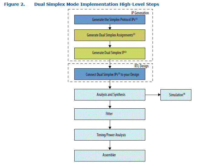
- Any modification or version update to the simplex protocol IPs that you use in the DS flow requires the DS IP to be regenerated.
- If you do not require DS mode, this step is not applicable.
- If you do not require DS mode, connect the simplex IP directly in your design.
- You can simulate the DS IP after Analysis and Elaboration.
Understanding and Planning Dual Simplex Interfaces
Before starting with your DS mode implementation, determine and plan the simplex IPs (transmitter and receiver) that you want to place in the same transceiver channel. If the simplex IPs in your design do not need to be placed in the same transceiver channel, the DS mode flow described in this document is not applicable and you can proceed to integrate the simplex IPs directly into your RTL design.
There are two groups of protocol IPs that can support DS mode:
- SDI, HDMI and DisplayPort
- SerialLite IV, JESD204C and JESD204B
- Upon determining the supported protocol IPs for DS mode, plan how your simplex IPs are paired (transmitter and receiver in the same channel) across the utilized channels. At this point, the planning is based on logical channel placement to establish the DS Group which you can use later for DS IP generation. You can perform the physical pin placement assignment after the IP generation stage.
- The following examples illustrate how to plan for the simplex IPs pairing in DS mode to establish a DS Group. A DS Group is defined as a set of simplex IPs that has at least one channel in DS mode.
Example 1: One SDI Transmitter Paired With One SDI Receiver
In this example, one SDI transmitter is paired with one SDI receiver to form a DS group as shown in the following figure.

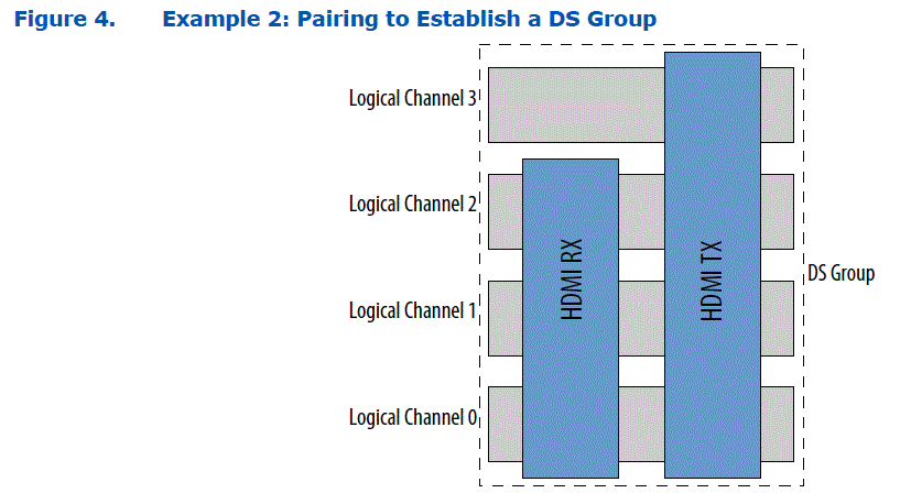
Example 2: One HDMI Transmitter Paired With One HDMI Receiver
In this example, one HDMI transmitter is paired with one HDMI receiver to form a DS group as shown in the following figure. You can place the HDMI receiver in channels 0-2 or channels 1-3.
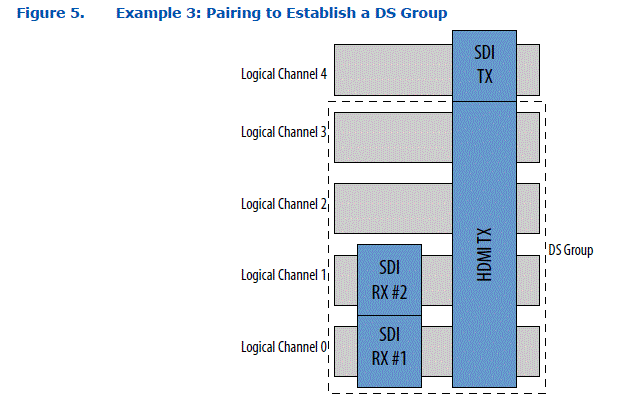
Example 3: One HDMI Transmitter Paired With Two SDI Receivers and a SDI Transmitter
In this example, one HDMI transmitter is paired with two SDI receivers to form a DS group along with one unpaired SDI transmitter as shown in the following figure. You can logically place the two SDI receivers in different locations provided that they pair with the HDMI transmitter channels. Since the SDI transmitter is not paired with another simplex IP, it is not a part of the DS group (you cannot include it in the DS group) and does not require the DS flow.
When planning your simplex IP pairing for DS mode, you must consider the following:
- TX bonding placement—though pairing is based on logical placement, the multi-channel transmitter IPs require bonding, and must meet the physical channel placement requirements as described in Channel Placement for PMA Direct Configuration for Bonded Lane Aggregation figure of the GTS Transceiver PHY User Guide.
- Same System PLL for TX and RX—simplex IPs that are paired in DS mode that use system PLL clocking mode must utilize the same System PLL for that channel. Simplex IPs that use PMA clocking mode can only be paired with another simplex IP with PMA clocking mode. Pairing PMA clocking mode and system PLL mode within a channel is not supported.
- FEC usage for TX and RX—simplex IPs that are paired in DS mode for a channel must have the same FEC setting (either enabled or not used). For example, if you have a GTS SerialLite IV IP TX with FEC enabled, you can only pair it with another GTS SerialLite IV IP RX with FEC enabled.
- Avalon® memory-mapped interface access—the transmitter and receiver share one Avalon memory-mapped interface to access each channel. When simplex IPs are paired in DS mode, the generated DS IP includes an Avalon memory-mapped interface arbiter that retains the individual transmitter IP Avalon memory-mapped interface and receiver IP Avalon memory-mapped interface interfaces. This is the same as when you are not using the DS mode.
Implementing Dual Simplex Interfaces
This chapter describes a dual simplex implementation based on example 2 in the Understanding and Planning Dual Simplex Interfaces chapter. The DS implementation combines the HDMI protocol simplex TX and simplex RX but with different configuration rates.
Generating the Simplex IP
You must first create and generate each individual simplex IP separately by following the IP specific user guide.
Note:
- For SDI, you must create the simplex IP with the Both Base and PHY parameter selected for the SDI_II wrapper option in the GTS SDI II Intel FPGA IP.
- For HDMI, you must create the simplex IP with the HDMI and Transceiver parameter selected for the HDMI wrapper option in the GTS HDMI Intel FPGA IP.
- For DisplayPort, you must create the simplex IP using the GTS DisplayPort PHY Altera FPGA IP.
- For JESD204C, you must create the simplex IP with the Both Base and PHY or the PHY Only parameter selected for the JESD204C wrapper option in the GTS JESD204C Intel FPGA IP.
- For JESD204B, you must create the simplex IP with the Both Base and PHY or the PHY Only parameter selected for the JESD204B wrapper option in the GTS JESD204B Intel FPGA IP.
- For Serial Lite IV, you must create the simplex IP by selecting Rx or Tx option for the PMA mode parameter. For RS-FEC, you must enable the Enable RS-FEC parameter and also enable the RS-FEC enabled on the other Serial Lite IV Simplex IP placed at the same channel(s) parameter under the Simplex Merging pane in the IP tab.
To generate the HDMI simplex IP, follow these steps:
- Create the HDMI simplex TX IP and HDMI simplex RX IP by choosing the HDMI and Transceiver parameter and other relevant parameters for your design using the GTS HDMI Intel FPGA IP.
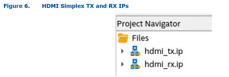
- Generate the IP files for the HDMI simplex IPs by clicking IP Generation step in the Compilation Dashboard of Quartus Prime Pro Edition software as shown in the following figure.

Once the IP generation completes successfully, the IP Generation step turns green with a check mark next to it as shown in the following figure. 
Related Information
- GTS HDMI Intel FPGA IP User Guide
- GTS SDI II Intel FPGA IP User Guide
- GTS DisplayPort PHY Altera FPGA IP User Guide
- GTS JESD204C Intel FPGA IP User Guide
- GTS JESD204C Intel FPGA IP Design Example User Guide
- GTS JESD204B Intel FPGA IP User Guide
- GTS JESD204B Intel FPGA IP Design Example User Guide
- GTS Serial Lite IV Intel FPGA IP User Guide
- GTS Serial Lite IV Intel FPGA IP Design Example User Guide
Using the Dual Simplex Assignment Editor
You can use the DS Assignment Editor tool to arrange and visualize the DS implementation according to the bank and channel arrangements. This section only covers the steps to use the DS Assignments Editor tool specifically for the DS implementation described in this user guide.
Note:
Refer to the HSSI Dual Simplex IP Generation Flow in the Quartus Prime Pro Edition User Guide: Design Compilation for additional details.
To use DS Assignment Editor to assign DS groups and save the dual simplex assignments, follow these steps:
- Click Assignments > Dual Simplex (DS) Assignment Editor in the Quartus Prime Pro Edition software. The DS Assignment Editor opens listing all the supported dual simplex IP in your design in the IP List and any existing DS assignments under DS Groups. In this example, the windows lists the generated HDMI TX and HDMI RX IPs as shown in the following figure.
Note: The DS Assignment Editor only displays the DS supported simplex IPs.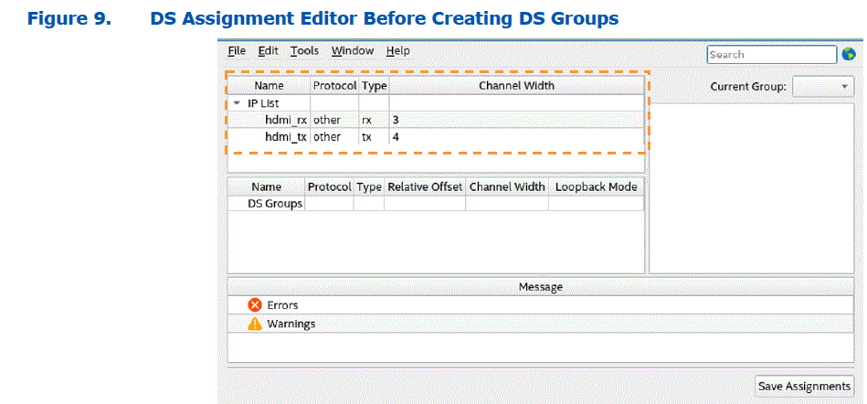
- In the DS Assignment Editor window, right-click the hdmi_rx instance under IP List, and click Create Instance In > New DS Group as shown in the following figure. This creates a new DS group called DS_GROUP_0 and adds the hdmi_rx instance to the DS Groups pane.

- Next, right-click the hdmi_tx instance under IP List, and click Create Instance In > DS_GROUP_0 as shown in the following figure. This adds the hdmi_tx instance to the DS Groups pane created in the previous step.
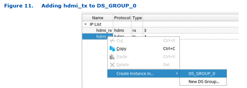
- The visualizer in the right pane of the DS Assignment Editor window displays the DS_GROUP_0 arrangement as shown in the following figure. The lower left pane displays the DS Groups and shows that hdmi_rx is instantiated as
hdmi_rx_inst0 and hdmi_tx is instantiated as hdmi_tx_inst0. If needed, you can rename the DS_GROUP_0, hdmi_rx_inst0, and hdmi_tx_inst0 instances by double-clicking the Name cells highlighted in the following figure. In addition, you can change the location of the instance by updating the Relative Offset setting in units of channels. You can also optionally enable the Loopback Mode to an available loopback mode for debug.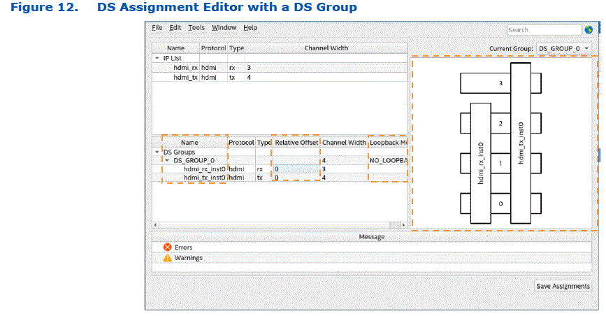
- If your design requires a shared input clock between the RX simplex and TX simplex modes, you can enable the Shared Clock feature by selecting each instantiated IP in the DS_GROUP_0 pane and clicking the Shared Clock checkbox as shown in the following figure. You can then choose the clock port from the IP Port drop down menu and provide a new port name in the Merged Port box.|
Note: Only certain clock ports are available for merging which is dependent on the protocol IP. You must check and confirm whether you can merge the clock ports before you proceed to do this step.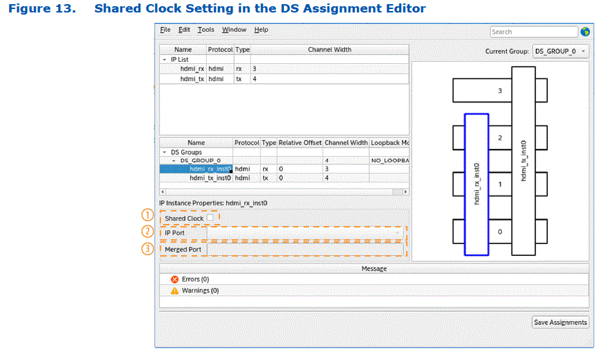
- To save the DS assignments, click Save Assignments and then click OK in the popup window.
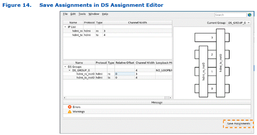
When you save the DS assignments, they are added automatically to the project .qsf file as shown in following figure. 
Generating the Dual Simplex IP
This section describes the steps to generate the previously created dual simplex group (DS_GROUP_0) in the DS Assignment Editor.
To generate the dual simplex IP and check the reports, follow these steps:
- Click HSSI Dual Simplex IP Generation in the Compilation Dashboard of the Quartus Prime Pro Edition software as shown in the following figure. The software first runs the IP Generation step and then runs the HSSI Dual Simplex IP Generation step.

- Click Open Compilation Report icon next to the HSSI Dual Simplex IP Generation step to access the DS IP reports that the Quartus Prime Pro Edition software as shown in the following figure. Successful generation of the DS IP is indicated by a check mark.

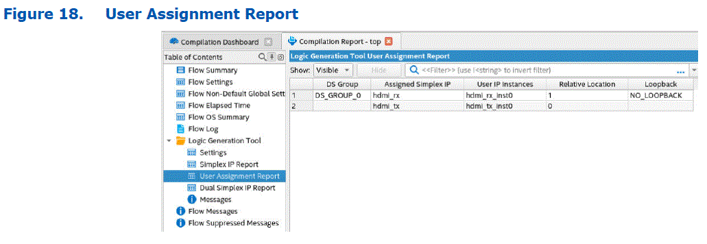
- Review the User Assignment Report (DS Assignment Editor Report) and Dual Simplex IP Report reports that the Quartus Prime Pro Edition software generates as shown in the following figures.

Connecting the Dual Simplex IP
- This section describes the steps to connect the previously generated dual simplex IP to your design.
- The design requires the GTS Reset Sequencer Intel FPGA IP and GTS System PLL Clocks Intel FPGA IP to function correctly, therefore both IPs must be instantiated and connected to the DS IP.
To connect the dual simplex IP, follow these steps:
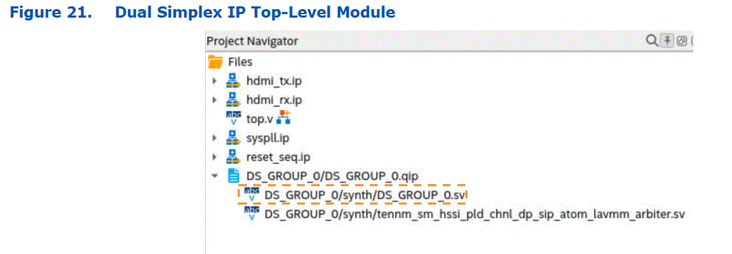
- The Quartus Prime Pro Edition software displays the DS IP and the simplex IPs in the Project Navigator pane as shown in the following figure.
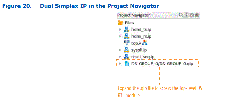 To view the top-level module of the DS IP, expand the DS_GROUP_0.qip file and click the DS_GROUP_0.sv SystemVerilog file as shown in the following figure.
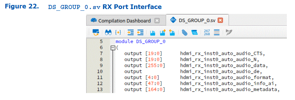
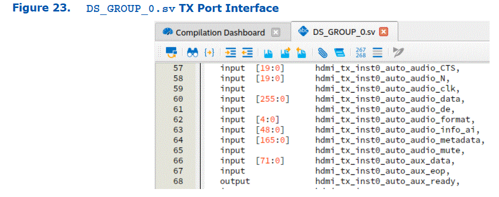
  The Quartus Prime Pro Edition software generates The DS IP port interface in the DS_GROUP_0.sv SystemVerilog file. The generated DS_GROUP_0.sv file retains all the ports as the simplex IPs and also merges the ports associated with the reset sequencer and system PLL (if used) as shown in the following figures.

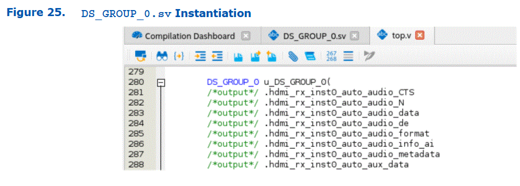
- Next, instantiate the DS IP module in your top-level design file and make the necessary connections as per your design needs as shown in the following figure.
Verifying the Dual Simplex IP Implementation
This section describes the steps to synthesize and verify the previously connected dual simplex IP in your design.
To synthesize and verify the dual simplex IP, follow these steps:
- Synthesize the design by running the Analysis & Synthesis step in the Quartus Prime Pro Edition software Compilation Dashboard. The following figure shows the dashboard after a successful Analysis & Synthesis compile.

- You can verify the DS IP in simulation upon successful completion of the Analysis & Synthesis. The following figure shows an example of the DS IP passing simulation with the HDMI testbench.
Note: You can simulate the DS IP after the Analysis & Elaboration stage completes.
- Perform a pin placement for the design. In the Quartus Prime Pro Edition software, click Assignments > Pin Planner to open the pin planner tool. Set the RX and TX pins to the same bank to combine the simplex TX and simplex RX pins to the same physical channel (for example Bank 4C) as shown in the following figure.
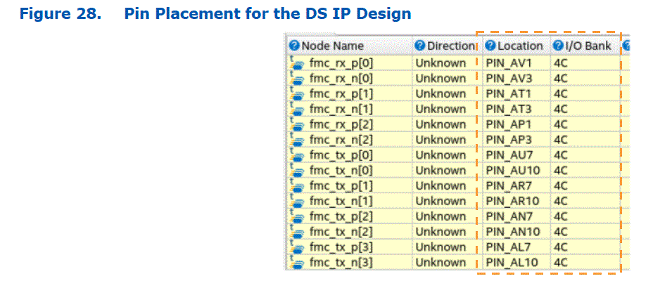
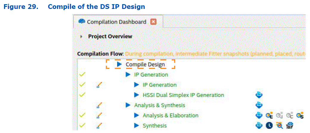
- Run a full compilation of the DS design implementation as shown in the following figure.
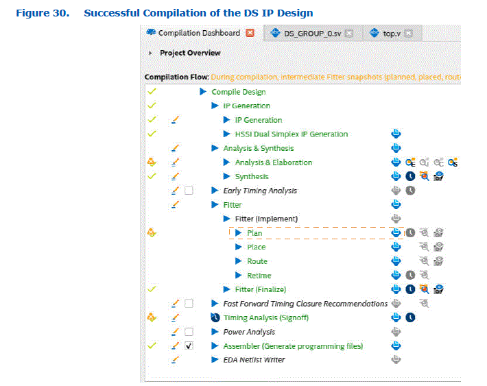
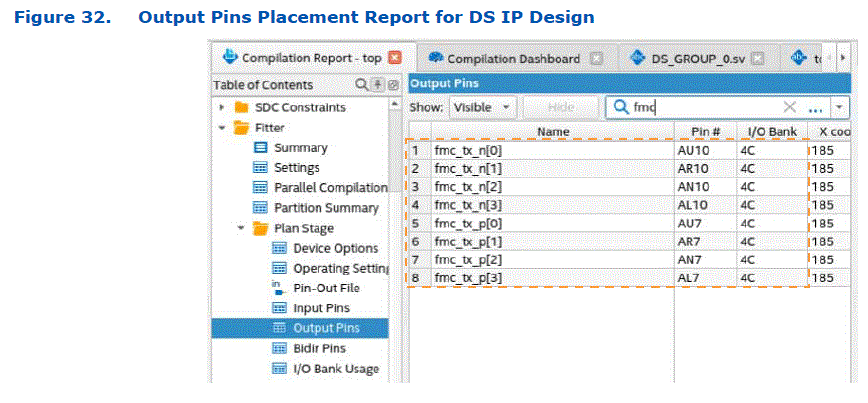
- Once the compile completes successfully, you can check the pin placement of the design by clicking the Fitter > Plan > Open Compilation Report step in the Quartus Prime Pro Edition software Compilation Dashboard as shown in the following figure.
You can then verify that the Quartus Prime Pro Edition software placed the simplex TX and simplex RX pins according to the Pin Planner settings and the pins are successfully combined by checking the reports as shown in the following figures.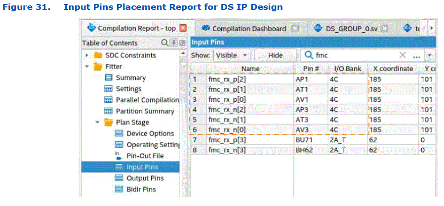
Document Revision History for the GTS Transceiver Dual Simplex Interfaces User Guide
| Document Version | Quartus Prime Version | Changes |
| 2025.01.24 | 24.3.1 | Made the following changes:
|
| 2024.10.07 | 24.3 | Made the following changes:
|
| 2024.08.19 | 24.2 | Initial release. |
FAQ
Q: Can I use custom TX/RX modes with the GTS PMA/FEC Direct PHY Intel FPGA IP in DS mode?
A: DS mode is only supported for specified simplex protocols and not for custom TX/RX modes with the GTS PMA/FEC Direct PHY Intel FPGA IP, except when the PMA configuration rules parameter is set to SDI or HDMI.
Documents / Resources
 |
Intel E-Series 5 GTS Transceiver [pdf] User Guide E-Series, D-Series, E-Series 5 GTS Transceiver, E-Series, 5 GTS Transceiver, GTS Transceiver, Transceiver |
