InoSmart GW710 Gateway Module

Product Information
Specifications
- Model: INOSMART GATEWAY MODUL GW710
- Revision: 3, 19.12.2024
- Minimum Firmware Versions: 1.6.221, 1.0.76, 0.0.56
- Minimum App Version: v4.0.65
- Communication Ports: TCP 8883 and 18083
- Wi-Fi Frequency: 2.4GHz
FAQ
Q: How do I activate additional relays using the Inosmart App?
A: To activate individual relays, navigate to the Inosmart App and follow the specific instructions provided within the app’s interface.
Dear User,
Thank you for choosing to purchase the Gateway Module, which will allow you to connect your Inosmart system to your home Wi-fi network and thus manage it remotely.
Although our devices are easy to use, please take a few minutes to read the instructions below. We have prepared all the information you need to pay attention to, both for the first time and for subsequent use. To help you understand, you can also visit our website www.inosmart.info/bt and watch the accompanying video content on how our system works and how to use it.
We wish you a pleasant and easy use.
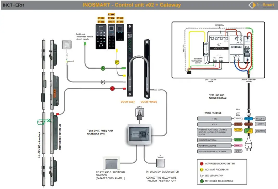
GATEWAY MODULE AND ITS FUNCTIONS
- Remote unlocking via smartphone
- Remote control of the Inosmart system
- 2 additional relays for connecting external devices (250V AC 3A, 30V DC 3A)
- Connection for door open/closed sensor
- Connection to the Internet network: WLAN or RJ-45
- 24V power supply
- Installation on a DIN rail
The Gateway module uses TCP ports 8883 and 18083 for communication, which must be opened on the firewall. In case of connection via WiFi, 2.4Ghz communication must be enabled on the home router (disable 5G).
CONNECTION SCHEME
CONNECTING THE GATEWAY MODULE TO THE INTERNET
After successfully connecting the Inosmart App to the control unit, all that is left to do is to connect to the internet using the Gateway module.
This can be configured in two ways:
- Via a local Wi-Fi network
- Network cable connections
When the Gateway module is detected by the control unit, it offers us a setting to connect to the module when connecting for the first time.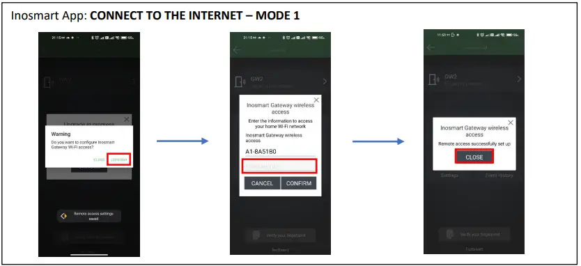
If you don’t set up access immediately, you can do so at any time later.
In the “Settings” menu, click “Inosmart Gateway Settings” and enter the name of the Wi-fi network and its password, then confirm by clicking “Save Settings”.
These are only available when connected via Bluetooth.
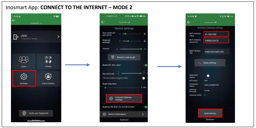
Once the settings are saved, the Gateway module connects to the home Wi-fi network and the MQTT server, signalled by two green LED lights.
In the case of connecting a LAN cable, the connection is made automatically, the green LED for connection on the Gateway module then flashes.
TROUBLESHOOTING PROBLEMS CONNECTING TO THE INTERNET
If the connection does not work, you need to enter the server IP “212.30.76.140” in the MQTT broker URL field instead of “mqtt.inosmart.info”.
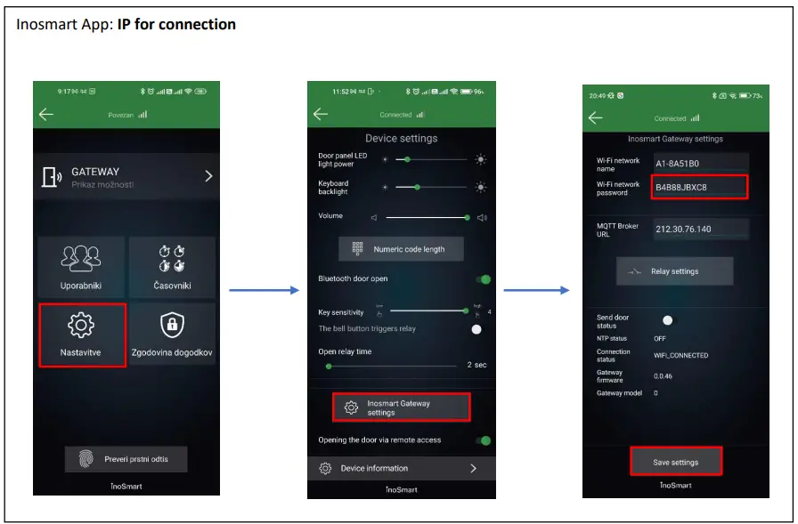
In case of problems connecting to the Internet network, it is necessary to check whether TCP ports 8883 and 18083 are open on the firewall to the URL mqtt.inosmart.info.
RESTORE FACTORY SETTINGS
Hold the reset button on the Gateway module for 10 seconds. After reset, the red LEDs on the Gateway Module will start flashing. All settings are erased and the device is restored to factory settings.
ACTIVATION OF ADDITIONAL RELAYS
In addition to the door in which the device is installed, you can unlock two additional (side or garage) doors or turn on/off any two devices connected to the control unit. You can enable individual people to open either additional e.g. garage door or main door and additional door together. Additional relays can be activated with all user identification methods: FINGERPRINTS, TELEPHONES and NUMERICAL CODES. For the selected persons, under each section, specify what the individual identification enables/disables.
With the Gateway module, additional relays can also be triggered remotely.
The activation of the additional relay can only be set via the Inosmart App.


Documents / Resources
 |
InoSmart GW710 Gateway Module [pdf] Instruction Manual GW710 Gateway Module, GW710, Gateway Module, Module |