![]() Connecting Devices, Enabling Services
Connecting Devices, Enabling Services
InHand Networks Edge Computing Gateway
IG902-FQ39
Quick Installation Manual
InHand Networks
www.inhandnetworks.com
Version: V1.0
February, 2019
IG902-FQ39 Networks Edge Computing Gateway
Copyright © 2019. All rights are reserved by InHand Networks and its licensors. Without the written permission of the Company, no unit or individual is allowed to excerpt, reproduce or transmit in any form part or all of the contents in the manual.
Preface
This document describes how to install and operate the edge computing gateway IG900 series products IG902-FQ39 of Beijing InHand Networks Technology. Before using these products, confirm the product model and the number of accessories inside the package.
Refer to the actual product during operation.
Packing List
Each edge computing gateway product is delivered with accessories (such as standard accessories) frequently used at the customer site. Check the received product against the packing list carefully. If any accessory is missing or damaged, contact the InHand sales personnel promptly.
InHand provides customers with optional accessories based on the characteristics of different sites. For details, see the optional accessories list.
Standard accessories:
| Accessory | Quantity | Description |
| Gateway | 1 | Edge computing gateway |
| Product document | 1 | Quick installation manual and user manual (Obtained by scanning a QR code) |
| Guide rail installation accessory | 1 | Used to fix the gateway |
| Power terminal | 1 | 7-pin industrial terminal |
| Network cable | 1 | 1.5 m long |
| Product warranty card | 1 | Warranty period: 1 year |
| Certificate of conformance | 1 | Certificate of conformance for the edge computing gateway |
Optional accessories:
| Accessory | Quantity | Description |
| AC power cord | 1 | Power cord for American English Australian or European Standard |
| Power Adapter | 1 | VDC Power Adapter |
| Antenna | 1 | Wi-Fi Antenna |
| 1 | GPS Antenna | |
| Serial Port | 1 | Gateway serial port line for debugging |
The following sections describe the panel, structure, and dimensions of the edge computing gateway.
2.1.Panel

![]() Caution
Caution
The IG900 series product is applicable to multiple panel appearances, as they have the same installation method. Refer to the actual product during operation.
2.2. Structure and Dimensions

 Figure 2- 2 Structure size
Installation
Precautions:
- Power supply requirements: 12 V DC (12–48 V DC). Pay attention to the voltage class. The rated current is 0.6 A (1.2–0.3 A).
- Environment requirements: operating temperature –25°C to 75°C; storage temperature –40°C to 85°C; relative humidity 5% to 95% (non-condensing). The temperature on the device surface may be high. Install the device in a restricted area and assess the surrounding environment.
- Avoid direct sunlight and keep away from thermal sources or areas with strong electromagnetic interferences.
- Install the gateway product on an industrial DIN-rail.
- Check whether the required cables and connectors are installed.
3.1.Installing and Uninstalling the Device on a DIN-Rail
3.1.1.Installing with a DIN-Rail
Procedure:
Step 1: Select an installation place and reserve enough space for installation.
Step 2: Insert the upper part of the DIN rail seat onto the DIN rail. Grab the lower end of the device and revolve it upward in the direction indicated by arrow 2 with gentle force, to insert the DIN rail seat onto the DIN rail. Check that the device is installed reliably on the DIN rail, as shown in Figure 3-1 on the right.
 Figure 3- 1 DIN rail installation schematic diagram
3.1.2.Uninstalling with a DIN-Rail
Procedure:
Step 1: Press the device downward in the direction indicated by arrow 1 in Figure 3-2 to create a gap near the lower end of the device so that the device isolates from the DIN rail.
Step 2: Revolve the device in the direction indicated by arrow 2, and grab the lower end of the device and move the device outward. Lift the device when its lower end isolates from the DIN rail. Then, take off the device from the DIN rail.
 Figure 3- 2 DIN rail disassembly schematic diagram
3.2.Installing and Uninstalling the Device in Wall-mounted Mode
3.2.1.Installing in Wall-mounted Mode
Procedure:
Step 1: Select an installation place and reserve enough space for installation.
Step 2: Install the wall mounting bracket on the back of the device by using a screwdriver, as shown in Figure 3-3.
 Figure 3- 3 Wall mounted installation diagram
Step 3: Take out the screws (packaged with the wall mounting bracket), fasten the screws in the installation positions by using the screwdriver, and pull down the device to make it secure, as shown in Figure 3-4.
 Figure 3- 4 Wall mounted installation diagram
3.2.2.Uninstalling in Wall-mounted Mode
Procedure:
Hold the device with one hand and unfasten the screws that fix the upper end of the device with the other hand, to remove the device from the installation place.
3.3.Installing an Antenna
Revolve the movable part of the metal SMAJ interface with gentle force until it cannot be revolved, in which state the outer thread of the antenna connection cable is invisible. Do not wring the antenna with force by grabbing the black plastic cover.
![]() Note
Note
- IG900 supports dual antenna: ANT antenna and AUX antenna. The ANT antenna sends and receives data. The AUX antenna only increases the antenna signal strength and cannot be used independently for data transmission.
- Only the ANT antenna is used in normal cases. It is used with the AUX antenna only when signal is poor and signal strength must be improved.
3.4.Installing the Power Supply
Procedure:
Step 1: Remove the terminal from the gateway.
Step 2: Unfasten the locking screw on the terminal.
Step 3: Connect the power cable to the terminal and fasten the locking screw.
3.5.Installing the Ground Protection
Procedure:
Step 1: Unfasten the ground screw cap.
Step 2: Put the ground loop of the cabinet ground cable onto the ground post.
Step 3: Fasten the ground screw cap.
![]() Caution
Caution
Ground the gateway to improve its interference resistance. Connect the ground cable to the ground post of the gateway based on the operation environment.
3.6.Connecting the Network Cable
Connect the gateway to a PC directly by using the Ethernet cable.
3.7.Connecting Terminals
Terminals provide the RS232 and RS485 interface modes. Connect cables to the corresponding terminals before using the interfaces. During installation, remove the terminals from the device, unfasten the locking screws on the terminals, connect cables to the corresponding terminals, and fasten the screws. Sort the cables in order.
 Figure 3- 9 Terminal line
![]() Note
Note
This section is only applicable to IG900 with industrial interfaces.
Configuring Network Connection for a Wireless Gateway
4.1.Connecting to the Gateway
Set the IP address of the management PC and the IP addresses of the GE interfaces of the gateway to be in the same network segment. The gateway has two GE interfaces: GE0/1 and GE0/2. The initial IP address of GE0/1 is 192.168.1.1, and that of GE0/2 is 192.168.2.1. Both interfaces have the same subnet mask 255.255.255.0. The following describes how to connect GE0/2 to the management PC in the Windows operating system.
(![]() >Network and Sharing Center>Local
>Network and Sharing Center>Local
Connections>Property>TCP/IPv4>Advanced> IP Address>Add)
 Figure 4- 1 Gateway Settings
4.2.Logging in to the Gateway
Connect the PC to the gateway directly by using the network cable, start the web browser, enter https://192.168.2.1 in the address bar, and press Enter to jump to the web login page. Enter the user name (default: adm) and password (default: 123456), and click OK or press Enter to access the web configuration page.
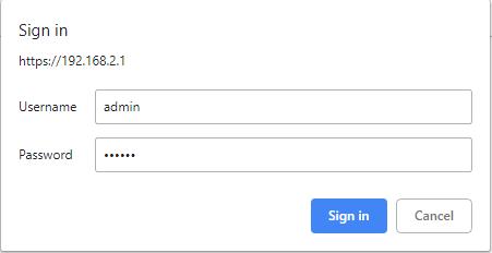 Figure 4-2 Login gateway Web management interface
Caution
By default, the DNS of the PC connected to GE0/1 cannot use the IP address of GE0/1; otherwise, public domain names cannot be accessed. You can enable the DHCP server or configure another DNS for public domain name access.
Quick Start Guide
5.1.Restoring the Default Settings
5.1.1.Web Page Mode
Log in to the web page and choose Administration>Config Management in the navigation tree to access the Config Management page. Click Restore default configuration and click OK. Then, restart the system to restore the default settings.
 Figure 5-1 Restore default configuration
5.1.2.Hardware Mode
Restore the default settings in hardware mode as follows:
Step 1: Find the Reset button on the device panel. For details, see section 2.1 “Panel.”
Step 2: Press and hold the Reset button with a fine pin within 10 seconds after the device is powered on.
Step 3: Release the Reset button after the ERR indicator is turned on.
Step 4: Press and hold the Reset button again when the ERR indicator is turned off several seconds later.
Step 5: Release the Reset button when the ERR indicator blinks. The default settings are restored successfully if the ERR indicatoris turned off later.
5.2.Importing and Exporting Configuration
Log in to the web page and choose Administration>Config Management in the navigation tree to access the Config Management page.
 Figure 5-2 Config Management
- Click Browse to select the configuration file. Then, click Import. After the configuration file is imported, restart the system (Administration>Reboot) to make the configuration take effect.
- Click Back Up running-config to export the currently applied configuration parameter file. Save the file. The exported file is in the .cnf format, and the default file name is running-config.cnf.
- Click Back Up startup-config to back up the configuration parameter file that is applied upon device startup. The exported file is in the .cnf format, and the default file name is startup-config.cnf.
5.3.Logs and Diagnosis Records
Log in to the web page and chooseAdministration>Log in the navigation tree to access the Log page. Click the corresponding buttons to download logs and diagnosis records.
 Figure 5-3 System log
Panel Indicators
6.1.LED Indicator


![]() Note
Note
Two SIM card indicators are provided. The indicator for SIM card 1 is turned on during the startup process and when startup is successful. In the last four situations, the indicator for the used SIM card is turned on. The following figure shows the indicator for SIM card 1.
FCC STATEMENT
This device complies with Part 15 of the FCC Rules. Operation is subject to the following two conditions: (1) This device may not cause harmful interference, and (2) this device must accept any interference received, including interference that may cause undesired operation.
NOTE 1: This equipment has been tested and found to comply with the limits for a Class B digital device , pursuant to part 15 of the FCC Rules. These limits are designed to provide reasonable protection against harmful interference in a residential installation. This equipment generates, uses and can radiate radio frequency energy and, if not installed and used in accordance with the instructions, installed and used in accordance with the instructions, may cause harmful interference to radio communications. However, there is no guarantee that interference will not occur in a particular installation. If this equipment does cause harmful interference to radio or television reception, which can be determined by turning the equipment off and on, the user is encouraged to try to correct the interference by one or more of the following measures:
- Reorient or relocate the receiving antenna.
- Increase the separation between the equipment and receiver.
- Connect the equipment into an outlet on a circuit different from that to which the receiver is connected.
- Consult the dealer or an experienced radio/TV technician for help.
NOTE 2: Any changes or modifications to this unit not expressly approved by the party responsible for compliance could void the user’s authority to operate the equipment.
RF Exposure
The equipment complies with FCC radiation exposure limits set forth for an uncontrolled environment. This device should be installed and operated with minimum distance 20cm between the radiator & your body. This transmitter must not be co-located or operating in conjunction with any other antenna or transmitter. The availability of some specific channels and/or operational frequency bands is country dependent and firmware programmed at the factory to match the intended destination. The firmware setting is not accessible by the end user.
IC STATEMENT
This device complies with Industry Canada license-exempt RSS standard(s): Operation is subject to the following Two conditions: (1) this device may not cause interference, and (2) This device must accept any interference, including interference that may cause undesired operation of the device.
Radiation Exposure Statement:
This equipment complies with IC radiation exposure limits set forth for an uncontrolled environment. This equipment should be installed and operated with minimum distance 20cm between the radiator & your body.
Documents / Resources
 |
inhand IG902-FQ39 Networks Edge Computing Gateway [pdf] Installation Guide IG902-FQ39 Networks Edge Computing Gateway, IG902-FQ39, Networks Edge Computing Gateway, Edge Computing Gateway, Computing Gateway, Gateway |