![]()
![]() Automotive Data Solutions Inc.
Automotive Data Solutions Inc.
INSTALL GUIDE
BLADE-AL(DL)-GM1-EN
GM1
AVAILABLE FOR : ADS-BLADE AL
Rev. Date: March 17, 2023
Doc. No.: ##81703##
PATENT NO. US 8,856,780 CA 2759622
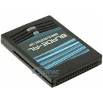
BLADE Series Web Programmable Data Immobilizer Bypass and Doorlock Integration Cartridge
PLEASE VISIT WWW.IDATALINK.COM FOR COMPLETE PRODUCT DETAILS
The brand names and logos found in this guide are property of their respective owners. Automotive Data Solutions Inc. © 2023

TERMS OF USE: automotive Data solutions Inc. (“aDs”) products are strictly intended for installation by Certifi ed technicians who are employed by a registered business specialized in the installation of automotive aftermarket electronics products. Prior to beginning installation of an aDs product in a vehicle, it is the Certifi ed technician’s responsibility to review the most current Product Guide, Install Guide and vehicle-specifi c notes available in Weblink®. aDs is not responsible for any damages whatsoever, including but not limited to any consequential damages, incidental damages, damages for loss of time, loss of earnings, loss of profi t, commercial loss, loss of economic opportunity and the like that may or may not have resulted from the use, misuse, improper installation or operation of its products. Purchasers sole contractual remedy is refund of the purchase price of the aDs product(s). aDs reserves itself the right to suspend any Weblink® account without notice and decline to offer technical support to non-Certifi ed technicians, non-compliant Certified technicians or end users.
NOTICE: The manufacturer will accept no responsibility for any electrical damage resulting from improper installation of this product, be that either damage to the vehicle itself or to the installed device. This device must be installed by a certified technician. This guide has been written for properly trained technicians; a certain level of skill & knowledge is therefore assumed. Please review the Installation Guide carefully before beginning any work.
INSTALL TYPE SELECTION
All in one
General Motors

* See heated accessories notice.
** Tach output is not available on vehicles with a duramax engine.
† The PK3 indicator will remain ON during the remote start sequence and will only turn OFF upon takeover.
§ Tach output is not available on these vehicles if they are equipped with a V8 engine.
INSTALL TYPE SELECTION

* See heated accessories notice.
** Tach output is not available on vehicles with a duramax engine.
† The PK3 indicator will remain ON during the remote start sequence and will only turn OFF upon takeover.
§ Tach output is not available on these vehicles if they are equipped with a V8 engine.
HEATED ACCESSORIES NOTICE
NOTE
I View compatibility chart for applicable vehicles.
II In all supported vehicle, heated accessories will automatically be activated 15 seconds after the remote starter is engaged and this only if the engine temperature is below 0 C (32 F).
- To disable this feature, connect [gray/red] wire to ground.

- To activate applicable heated accessories upon remote start regardless of engine temperature, connect [green/ red] wire to ground.

TYPE 1 – WIRING DIAGRAM
STANDARD 12 VOLT, GROUND AND IGNITION SWITCH CONNECTIONS ARE STILL REQUIRED FROM THE REMOTE STARTER.

TYPE 2 – WIRING DIAGRAM
STANDARD 12 VOLT, GROUND AND IGNITION SWITCH CONNECTIONS ARE STILL REQUIRED FROM THE REMOTE STARTER.

TYPE 3 – WIRING DIAGRAM
STANDARD 12 VOLT, GROUND AND IGNITION SWITCH CONNECTIONS ARE STILL REQUIRED FROM THE REMOTE STARTER.

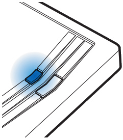
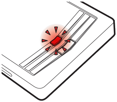
CARTRIDGE INSTALLATION
- Slide cartridge into unit. Notice button under LED.

- Ready for Module Programming Procedure.
MODULE PROGRAMMING PROCEDURE
- Insert key into ignition.
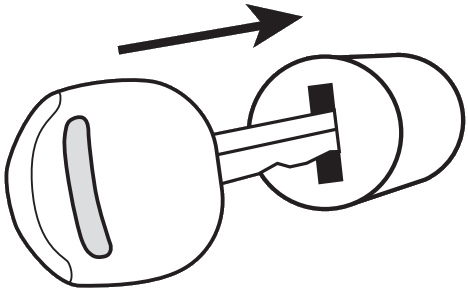
- Turn key to START position.

- Wait, LED will turn solid BLUE for 2 seconds.
- Turn key to OFF position.

- Module Programming Procedure completed.
IDENTIFY VEHICLE YEAR
- Locate the Vehicle Identifi cation Number (VIN), identify the 10th character then match it to its corresponding year.

MODULE DIAGNOSTICS
LED STATUS
 |
Flashing RED |
 |
Solid RED |
 |
Flashing BLUE |
 |
Solid BLUE then OFF |
 |
OFF |
DIAGNOSTICS
| DURING PROGRAMMING | DURING REMOTE START | WITH IGNITION OFF |
| Missing/wrong information from firmware or vehicle | Incorrectly programmed | Incorrectly programmed or connected |
| Waiting for more vehicle information | Incorrectly programmed | Not programmed waiting for more vehicle information |
| Additional steps required to complete programming | Correctly programmed and operational | False ground when running status from remote starter |
| Correctly programmed | Reset in progress | Reset in progress |
| No activity or already programmed | Invalid ground when running status from remote starter | At rest and ready for a remote start sequence |
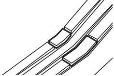
FACTORY RESET PROCEDURE
- DISCONNECT cartridge from remote starter.

- PRESS AND HOLD programming button while re-connecting cartridge to remote starter.

- LED will fl ash red. Immediately RELEASE programming button.
- LED will turn solid red for 2 seconds.
RESET COMPLETED.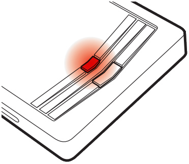
- RECONNECT all connectors.
Repeat programming procedure.
![]() Failure to follow procedure may result with a DTC or a CHECK ENGINE error message.
Failure to follow procedure may result with a DTC or a CHECK ENGINE error message.
Automotive Data Solutions Inc. © 2023
WWW.IDATALINK.COM
Documents / Resources
 |
idatalink BLADE Series Web Programmable Data Immobilizer Bypass and Doorlock Integration Cartridge [pdf] Installation Guide Yukon - Denali 99-02, Yukon - Denali 03-06, BLADE Series, BLADE Series Web Programmable Data Immobilizer Bypass and Doorlock Integration Cartridge, Web Programmable Data Immobilizer Bypass and Doorlock Integration Cartridge, Data Immobilizer Bypass and Doorlock Integration Cartridge, Immobilizer Bypass and Doorlock Integration Cartridge, Bypass and Doorlock Integration Cartridge, Doorlock Integration Cartridge, Integration Cartridge, Cartridge |