Quick Start
for tM-AD2
Dec 2015, Version 1.0.0
tM-AD2 Quick Start 
Congratulation!
Congratulations on purchasing the tM-AD2 the most popular automation solution for remote monitoring and control applications. This Quick Start Guide will provide the information needed to get started with the tM-AD2. Please also consult the User Manual for detailed information on the setup and use of the tM-AD2.
What’s in the shipping box?
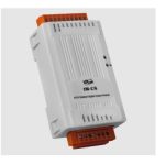
In addition to this guide, the shipping box includes the following items: tM-AD2
Technical Support
- ICP DAS Website
http://www.icpdas.com/
Understanding the Hardware Specifications and Wiring Diagrams
Before installing the hardware, you should have a basic understanding of hardware specifications and the wiring diagrams.
System Specifications
| Communication | |
| Interface | RS-485 |
| Format | (N, 8, 1), (N, 8, 2), (0, 8, 1), (E, 8, 1) |
| Baud Rate | 1200 ~ 115200 bps |
| Protocol | DCON, Modbus/RTU, Modbus/ASCII |
| Dual Watchdog | Yes, Module (2.3 seconds), Communication (Programmable) |
| LED Indicators | |
| Power | 1 LED as Power Indicator |
| Isolation | |
| Intra-module Isolation, Field-to-Logic | 3000 Vdc |
| EMS Protection | |
| ESD (IEC 61000-4-2) | ±4 kV Contact for Each Terminal |
| ±8 kV Air for Random Point | |
| EFT (IEC 61000-4-4) | ±4 kV for Power |
| Surge (IEC 61000-4-5) | ±3 kV for Power |
| Power Requirements | |
| Reverse Polarity Protection | Yes |
| Powered from Terminal Block | Yes, 10 fu 30 Voc |
| Consumption | 0.8 W Max. |
| Mechanical | |
| Dimensions (W x L x H) | 52 mm 98 mm 27 mm |
| Installation | DIN-Rail Mounting |
| Environment | |
| Operating Temperature | -25 ∼ +75°C |
| Storage Temperature | -30 ∼ +75°C |
| Humidity | 10 fu 95% RH, Non-condensing |
I/O Specifications
| Analog Input | ||
| Input Channels | 2 Single-ended | |
| Type | 0 ~ 500 m V, 0~ 1 V, 0~ 2.5 V, 0 ~ 5 V, 0~ 10 V, 0~ 20 mA, 4~ 20 mA | |
| Resolution | Normal Mode | 14-bit |
| Fast Mode | 12-bit | |
| Sampling Rate | Normal Mode | 10 Hz total |
| Fast Mode | 200 Hz total | |
| Accuracy | Normal Mode | +1-0.1% |
| Fast Mode | +/-0.5% | |
| Zero Drift | +/-20 uV/°C | |
| Span Drift | +/-25 ppm/°C | |
| Input Impedance | Voltage 10 Mfg |
|
| Current | 125 Ω | |
| Overvoltage Protection | 120 Vcc | |
| Overcurrent Protection | Yes, 50 mA at 110 VDC | |
| Open Wire Detection for 4 n 20 mA | Yes | |
Wire Connection:

Pin Assignment :
Pin Assignments

Booting the tM-Series in Init Mode
Make sure the switch is placed in the “Init” position. Connecting to the PC and the Power Supply
The TM-Series series is equipped with an RS-485 port for connection to a 232/USB converter to a PC

Installing the DCON Utility
The DCON Utility is an easy-to-use tool designed to enable the simple configuration of I/O modules that use the DCON protocol.
Step 1: Locate the DCON Utility

The DCON utility can be obtained from the companion CD or from the ICPDAS FTP site:
ftp://ftp.icpdas.com/pub/cd/8000cd/napdos/driver/dcon_utility/
CD:\Napdos\Driver\DCON_Utility
Using the DCON Utility to Initialize the TM-Series Module
The M-Series is an I/O module based on the DCON protocol, meaning that you can use the DCON Utility to easily initialize it.
Step 1: Run the DCON Utility_Pro

Step 2: Use the COM1 port to communicate with the TM-Series
Click the “COM Port” option from the menu and a dialog box will be displayed that will allow you to set the communication parameters as described in the table below.

| Communication parameter | Factory default Value |
| Address | 0 |
| Baud Rate | 9600 |
| Protocol | DCON |
| Checksum | Disabled |
| Parity | N,8,1 |
Step 3: Search for the tM-Series module
Click the “Start Search” button from the toolbox to search for the tM-Series module.
After the TM-Series module is displayed in the list, click the “Stop Search” button.

Step 4: Connect to the TM-Series
After clicking on the name of the module in the list, a dialog box will be displayed.

Step 5: Initialize the TM-Series module
Set the “Address” field in the dialog box to 1 and then click the “Setting Module Configurations ” button to save the settings.

Rebooting the TM-SeriesModule in Normal Mode
Make sure the INIT switch is placed in the “Normal” position.
Starting the Module Operation
After rebooting the TM-Series module, search for the module to make sure the settings have been changed. You can double click on the name of the module in the list to open

Modbus Address Mapping
| Address | Description | Attribute | ||||||||||||||||||||
| 30001 – 30002 40001 – 40002 |
Analog input value of channel 0 to 1 | R | ||||||||||||||||||||
| 40257 – 40258 | Analog input type code of channel 0 to 1 | R/W | ||||||||||||||||||||
| 40481 | Firmware version (low word) | R | ||||||||||||||||||||
| 40482 | Firmware version (high word) | R | ||||||||||||||||||||
| 40483 | Module name (low word) , 0x2001 | R | ||||||||||||||||||||
| 40484 | Module name (high word) , 0x0700 | R | ||||||||||||||||||||
| 40485 | Module address, valid range: 1 – 247 | R/W | ||||||||||||||||||||
| 40486 | Bits 5:0 Baud rate, 0x03 – OxOA
Bits 7:6 |
R/W | ||||||||||||||||||||
| 40488 | Modbus response delay time in ms, valid range: 0 – 30 | R/W | ||||||||||||||||||||
| 40489 | Host watchdog timeout value, 0 – 255, in 0.1s | R/W | ||||||||||||||||||||
| 40490 | Channel enable/disable, 00h – 03h | R/W | ||||||||||||||||||||
| 40492 | Host watchdog timeout count, write 0 to clear | R/W | ||||||||||||||||||||
| 40494 | 4mA under range threshold in 0.1 mA, 0 – 40 | R/W |
| 10129 – 10130 00129 – 00130 |
Over/under range status of channel 0 to 1 for 4 – 20mA or 0 – 20mA ranges | R |
| 257 | Protocol, 0: DCON, 1: Modbus RTU | R/W |
| 258 | Protocol, 0: determined by 00257, 1: Modbus ASCII | R/W |
| 261 | 1: enable, 0: disable host watchdog | R/W |
| 269 | Modbus data format, 0: hex, 1: engineering | R/W |
| 270 | Host watchdog timeout status, write 1 to clear the host watchdog timeout status | R/W |
| 271 | 1: enable, 0: disable fast mode | R/W |
| 273 | Reset status, 1: first read after powered on, 0: not the first read after powered on | R |
Copyright © 2015 ICP DAS Co., Ltd. All Rights Reserved. E-mail: service@icpdas.com
Documents / Resources
 |
ICP DAS tM-AD2 2-Channel Analog Input [pdf] User Guide tM-AD2, 2-Channel Analog Input, tM-AD2 2-Channel Analog Input |