ICON Process Controls TI3B Series Insertion Paddle Wheel Flow Meter Sensor
![]()
Product Usage Instructions
Before installation or removal, ensure to de-pressurize and vent the system. Confirm chemical compatibility before use. Do not exceed maximum temperature or pressure specifications. Always wear safety goggles or a face shield during installation and service. Do not alter product construction.
Installation
- Lubricate O-rings with a compatible viscous lubricant.
- Carefully lower the sensor into the fitting using an alternating or twisting motion. Do not force it.
- Ensure the tab or notch on the sensor is parallel to the flow direction.
- Hand tighten the sensor cap without using any tools to prevent damage to threads.
- Lubricate the inside of the insertion fitting with silicone.
Safety Information
- De-pressurize and vent system prior to installation or removal
- Confirm chemical compatibility before use
- DO NOT exceed maximum temperature or pressure specifications
- ALWAYS wear safety goggles or face-shield during installation and/or service
- DO NOT alter product construction
![]() Warning | Caution | Danger
Warning | Caution | Danger
Indicates a potential hazard. Failure to follow all warnings may lead to equipment damage, injury, or death.
![]() Note | Technical Notes
Note | Technical Notes
Highlights additional information or detailed procedure.
![]() Hand Tighten Only
Hand Tighten Only
Over tightening may permanently damage product threads and lead to failure of the retaining nut.
![]() Do Not Use Tools
Do Not Use Tools
Use of tool(s) may damage produced beyond repair and potentially void product warranty.
![]() Personal Protective Equipment (PPE)
Personal Protective Equipment (PPE)
Always utilize the most appropriate PPE during installation and service of Truflo® products.
![]() Pressurized System Warning
Pressurized System Warning
Sensor may be under pressure. Take caution to vent system prior to installation or removal. Failure to do so may result in equipment damage and/or serious injury.![]()
Display Characteristics
![]()
Technical Specifications
| General | ||
| Operating Range | 0.3 to 33 ft/s | 0.1 to 10 m/s |
| Pipe Size Range | ½ to 24″ | DN15 to DN600 |
| Linearity | ±0.5% of F.S @ 25°C | 77°F | |
| Repeatability | ±0.5% of F.S @ 25°C | 77°F | |
| Wetted Materials | ||
| Sensor Body | PVC (Dark) | PP (Pigmented) | PVDF (Natural) | 316SS | |
| O-Rings | FKM | EPDM* | FFKM* | |
| Rotor Pin | Bushings | Zirconium Ceramic | ZrO2 | |
| Paddle | Rotor | ETFE Tefzel® | |
| Electrical | ||
| Battery | 5000 | 9000 mAh | |
| Display | ||
| LCD | Flow Rate + Flow Totalizer | ||
| Max. Temperature/Pressure Rating – Standard and Integral Sensor | Non-Shock | ||
| PVC | 180 Psi @ 68°F | 40 Psi @ 140°F | 12.5 Bar @ 20°C | 2.7 Bar @ 60°F |
| PP | 180 Psi @ 68°F | 40 Psi @ 190°F | 12.5 Bar @ 20°C | 2.7 Bar @ 88°F |
| PVDF | 200 Psi @ 68°F | 40 Psi @ 240°F | 14 Bar @ 20°C | 2.7 Bar @ 115°F |
| 316SS | 200 Psi @ 180°F | 40 Psi @ 300°F | 14 Bar @ 82°C | 2.7 Bar @ 148°F |
| Operating Temperature | ||
| PVC | 32°F to 140°F | 0°C to 60°C |
| PP | -4°F to 190°F | -20°C to 88°C |
| PVDF | -40°F to 240°F | -40°C to 115°C |
| 316SS | -40°F to 300°F | -40°C to 148°C |
| Standards and Approvals | ||
| CE | FCC | RoHS Compliant | ||
See Temperature and Pressure Graphs for more information
Product Description
The TI Series insertion plastic paddle wheel flow meter has been engineered to provide long-term accurate flow measurement in tough industrial applications. The paddle wheel assembly consists of a engineered Tefzel® paddle and micro-polished zirconium ceramic rotor pin and bushings. High performance Tefzel® and Zirconium materials have been selected due to their excellent chemical and wear resistant properties.
![]()
Features
- ½” – 24” Line Sizes
- Flow Rate | Total
New ShearPro® Design
- Contoured Flow Profile
- Reduced Turbulence = Increased Longevity
- 78% Less Drag than Old Flat Paddle Design*
*Ref: NASA “Shape Effects on Drag”
![]()
360º Shielded Rotor Design
- Eliminates Finger Spread
- No Lost Paddles
Installation
Very Important
- Lubricate O-rings with a viscous lubricant, compatible with the materials of construction.
- Using an alternating | twisting motion, carefully lower the sensor into the fitting. | Do Not Force | Fig-3
- Ensure tab | notch are parallel to flow direction | Fig-4
![]()
Hand tighten the sensor cap. DO NOT use any tools on the sensor cap or the cap threads or fitting threads may be damaged. | Fig-5 ![]()
![]()
Correct Sensor Position
- Locate the flow meter positioning tab and clamp saddle notch.
- Engage one thread of the sensor cap, then turn the sensor until the alignment tab is seated in the fitting notch. Ensure tab is parallel to flow direction.
- Hand tighten the screw cap.
- DO NOT use any tools — threads may be damaged.
- Ensure meter is firmly in place.
![]()
Correct Sensor Position Setup
TI Series flow meters measure liquid media only. There should be no air bubbles and the pipe must always remain full. To ensure accurate flow measurement, the placement of the flow meters needs to adhere to specific parameters. This requires a straight run pipe with a minimum number of pipe diameters distance upstream and downstream of the flow sensor.![]()
![]()
![]()
Maximum % of solids: 10% with particle size not exceeding 0.5mm cross section or length
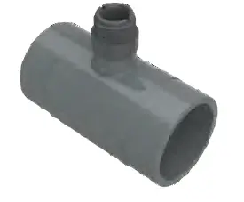
Fittings and K-Factor
| TEE FITTINGS | ||||
| Tee Fitting | K-Factor |
Sensor Length |
||
| IN | DN | LPM | GPM | |
| ½” (V1) | 15 | 156.1 | 593.0 | S |
| ½” (V2) | 15 | 267.6 | 1013.0 | S |
| ¾” | 20 | 160.0 | 604.0 | S |
| 1″ | 25 | 108.0 | 408.0 | S |
| 1½” | 40 | 37.0 | 140.0 | S |
| 2″ | 50 | 21.6 | 81.7 | S |
| 2½” | 65 | 14.4 | 54.4 | S |
| 3″ | 80 | 9.3 | 35.0 | S |
| 4″ | 100 | 5.2 | 19.8 | S |
| CLAMP-ON SADDLES | ||||
| Clamp Saddles | K-Factor |
Sensor Length |
||
| IN | DN | LPM | GPM | |
| 2″ | 50 | 21.6 | 81.7 | S |
| 3″ | 80 | 9.3 | 35.0 | S |
| 4″ | 100 | 5.2 | 19.8 | S |
| 6″ | 150 | 2.4 | 9.2 | L |
| 8″ | 200 | 1.4 | 5.2 | L |
| CPVC SOCKET WELD-ON ADAPTERS | ||||
| Weld On
Adapter |
K-Factor |
Sensor Length |
||
| IN | DN | LPM | GPM | |
| 2″ | 50 | 14.4 | 54.4 | S |
| 2½” | 65 | 9.3 | 35.5 | S |
| 3″ | 80 | 9.3 | 35.0 | S |
| 4″ | 100 | 5.2 | 19.8 | S |
| 6″ | 150 | 2.4 | 9.2 | L |
| 8″ | 200 | 1.4 | 5.2 | L |
| 10″ | 250 | 0.91 | 3.4 | L |
| 12″ | 300 | 0.65 | 2.5 | L |
| 14″ | 400 | 0.5 | 1.8 | L |
| 16″ | 500 | 0.4 | 1.4 | L |
| 18″ | 600 | 0.3 | 1.1 | L |
| 20″ | 800 | 0.23 | 0.9 | L |
| 24″ | 1000 | 0.16 | 0.6 | L |
Pressure vs. Temperature![]()
Min/Max Flow Rates
| Pipe Size (O.D.) | LPM | GPM | LPM | GPM |
| 0.3m/s min. | 10m/s max | |
| ½” | DN15 | 3.5 | 1.0 | 120.0 | 32.0 |
| ¾” | DN20 | 5.0 | 1.5 | 170.0 | 45.0 |
| 1″ | DN25 | 9.0 | 2.5 | 300.0 | 79.0 |
| 1 ½” | DN40 | 25.0 | 6.5 | 850.0 | 225.0 |
| 2″ | DN50 | 40.0 | 10.5 | 1350.0 | 357.0 |
| 2 ½” | DN60 | 60.0 | 16.0 | 1850.0 | 357.0 |
| 3″ | DN80 | 90.0 | 24.0 | 2800.0 | 739.0 |
| 4″ | DN100 | 125.0 | 33.0 | 4350.0 | 1149.0 |
| 6″ | DN150 | 230.0 | 60.0 | 7590.0 | 1997.0 |
| 8″ | DN200 | 315.0 | 82.0 | 10395.0 | 2735.0 |
Unit Selection![]()
Programming
![]()
![]()
![]()
Flow Totalizer – Full Digit Display
In the Totalizer Mode (GAL, LTR, KL)
- Hold the
 key for 3 seconds to show current value of the 7th – 8th digits
 - After releasing the key the current value of the 1st – 6th digits will be displayed
Flow Totalizer Reset
![]()
Visual Alarm Settings
![]()
![]()
Battery Status Indicator
| Voltage of Battery | Symbol | Status |
| 3.0V | Full Scale | |
| < 3.0V | Mild Scale | |
| < 2.8V | Low Scale (Pilot BAT Flashing) | |
| < 2.6V | Low Voltage (Pilot BAT & Display Flashing) |
Sleep Settings![]()
Dimensions (mm)
![]()
Rotor Pin | Paddle Replacement
![]()
![]()
Battery Replacement
![]()
Model Selection
| PVC | PP | PVDF | ||
| Size | Part Number | Material |
| ½” – 4″ | TIB-P-S | PVC |
| 6″ – 24″ | TIB-P-L | PVC |
| 1″ – 4″ | TIB-PP-S | PP |
| 6″ – 24″ | TIB-PP-L | PP |
| 1″ – 4″ | TIB-PF-S | PVDF |
| 6″ – 24″ | TIB-PF-L | PVDF |
| 316 SS | ||
| Size | Part Number | Material |
| ½” – 4″ | TI3B-SS-S | 316 SS |
| 6″ – 24″ | TI3B-SS-L | 316 SS |
- Add Suffix –
- ‘E’ – EPDM Seals
Installation Fittings![]()
SA
Clamp-On Saddle Fittings
- PVC Material
- Viton® O-Rings
- Available in Metric DIN
- Will Accept Signet® Type Flow Meter
| PVC | |
| Size | Part Number |
| 2″ | SA020 |
| 3″ | SA030 |
| 4″ | SA040 |
| 6″ | SA060 |
| 8″ | SA080 |
PT | PPT | PFT
Installation Fittings
- PVC | PP | PVDF
- Socket End Connections
- Will Accept Signet® Type Flow Meter
- True-Union Design
| PVDF | PVC | PP | |
| Size | Part Number | Part Number | Part Number |
| ½” | PFT005 | PT005 | PPT005 |
| ¾” | PFT007 | PT007 | PPT007 |
| 1” | PFT010 | PT010 | PPT010 |
| 1½” | PFT015 | PT015 | PPT015 |
| 2” | PFT020 | PT020 | PPT020 |
Add Suffix –
- ‘E’ – EPDM Seals
- ‘T’ – NPT End Connectors
- ‘B’ – Butt Fused End Connections for PP or PVDF
![]()
SAR
Clamp-On Saddle Fittings (SDR Pipe)
- PVC Material
- Viton® O-Rings
- Available in Metric DIN
- Will Accept Signet® Type Flow Meter

| PVC | |
| Size | Part Number |
| 2″ | SAR020 |
| 3″ | SAR030 |
| 4″ | SAR040 |
| 6″ | SAR060 |
| 8″ | SAR080 |
| 10″ | SAR100 |
| 12″ | SAR120 |
| 14″ | SAR140 |
| 16″ | SAR160 |
CT
CPVC Tee Installation Fitting
- 1”-4” Pipe Sizes
- Easy to Install
- Will Accept Signet® Flow Meter
| CPVC | |
| Size | Part Number |
| 1″ | CT010 |
| 1 ½” | CT015 |
| 2″ | CT020 |
| 3″ | CT030 |
| 4″ | CT040 |
PG
Glue-On Adapter
- 2”-24” Pipe Sizes
- Easy to Install
- Will Accept Signet® Flow Meter
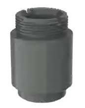
| Glue-On Adapter – CPVC | |
| Size | Part Number |
| 2”- 4” | PG4 |
| 6”- 24” | PG24 |
- Add Suffix –
- ‘E’ – EPDM Seals
- ‘T’ – NPT End Connectors
- ‘B’ – Butt Fused End Connections for PP or PVDF
SWOL
Weld-On Adapter
- 2”-12” Pipe Sizes
- 316SS Weld-o-let with PVDF insert
- Easy to Install
- Will Accept Signet® Flow Meter
![]()
| Weld-On Adapter – 316 SS | |
| Size | Part Number |
| 3” | SWOL3 |
| 4” | SWOL4 |
| 6” | SWOL6 |
| 8” | SWOL8 |
| 10” | SWOL10 |
| 12” | SWOL12 |
SST
316SS TI3 Series NPT Tee Fittings
Will Accept Signet® Type Flow Meter![]()
| Threaded Tee Fitting – 316 SS | |
| Size | Part Number |
| ½” | SST005 |
| ¾” | SST007 |
| 1″ | SST010 |
| 1 ½” | SST015 |
| 2″ | SST020 |
| 3″ | SST030 |
| 4″ | SST040 |
SSS
316SS TI3 Series Sanitary Tee Fittings
Will Accept Signet® Type Flow Meter![]()
| Sanitary Tee Fitting – 316 SS | |
| Size | Part Number |
| ½” | SSS005 |
| ¾” | SSS007 |
| 1″ | SSS010 |
| 1 ½” | SSS015 |
| 2″ | SSS020 |
| 3″ | SSS030 |
| 4″ | SSS040 |
SSF
316SS TI3 Series Flanged Tee Fittings
Will Accept Signet® Type Flow Meter![]()
| Flanged Tee Fitting – 316 SS | |
| Size | Part Number |
| ½” | SSF005 |
| ¾” | SSF007 |
| 1″ | SSF010 |
| 1 ½” | SSF015 |
| 2″ | SSF020 |
| 3″ | SSF030 |
| 4″ | SSF040 |
Warranty, Returns and Limitations
Warranty
Icon Process Controls Ltd warrants to the original purchaser of its products that such products will be free from defects in material and workmanship under normal use and service in accordance with instructions furnished by Icon Process Controls Ltd for a period of one year from the date of sale of such products. Icon Process Controls Ltd obligation under this warranty is solely and exclusively limited to the repair or replacement, at Icon Process Controls Ltd option, of the products or components, which Icon Process Controls Ltd examination determines to its satisfaction to be defective in material or workmanship within the warranty period. Icon Process Controls Ltd must be notified pursuant to the instructions below of any claim under this warranty within thirty (30) days of any claimed lack of conformity of the product. Any product repaired under this warranty will be warranted only for the remainder of the original warranty period. Any product provided as a replacement under this warranty will be warranted for the one year from the date of replacement.
Returns
Products cannot be returned to Icon Process Controls Ltd without prior authorization. To return a product that is thought to be defective submit a customer return (MRA) request form and follow the instructions therein. All warranty and non-warranty product returns to Icon Process Controls Ltd must be shipped prepaid and insured. Icon Process Controls Ltd will not be responsible for any products lost or damaged in shipment.
Limitations
This warranty does not apply to products which:
- are beyond the warranty period or are products for which the original purchaser does not follow the warranty procedures outlined above;
- have been subjected to electrical, mechanical or chemical damage due to improper, accidental or negligent use;
- have been modified or altered;
- anyone other than service personnel authorized by Icon Process Controls Ltd have attempted to repair;
- have been involved in accidents or natural disasters; or
- are damaged during return shipment to Icon Process Controls Ltd
Icon Process Controls Ltd reserves the right to unilaterally waive this warranty and dispose of any product returned to Icon Process Controls Ltd where:
- there is evidence of a potentially hazardous material present with the product;
- or the product has remained unclaimed at Icon Process Controls Ltd for more than 30 days after Icon Process Controls Ltd has dutifully requested disposition.
This warranty contains the sole express warranty made by Icon Process Controls Ltd in connection with its products. ALL IMPLIED WARRANTIES, INCLUDING WITHOUT LIMITATION, THE WARRANTIES OF MERCHANTABILITY AND FITNESS FOR A PARTICULAR PURPOSE, ARE EXPRESSLY DISCLAIMED. The remedies of repair or replacement as stated above are the exclusive remedies for the breach of this warranty. IN NO EVENT SHALL Icon Process Controls Ltd BE LIABLE FOR ANY INCIDENTAL OR CONSEQUENTIAL DAMAGES OF ANY KIND INCLUDING PERSONAL OR REAL PROPERTY OR FOR INJURY TO ANY PERSON. THIS WARRANTY CONSTITUTES THE FINAL, COMPLETE AND EXCLUSIVE STATEMENT OF WARRANTY TERMS AND NO PERSON IS AUTHORIZED TO MAKE ANY OTHER WARRANTIES OR REPRESENTATIONS ON BEHALF OF Icon Process Controls Ltd. This warranty will be interpreted pursuant to the laws of the province of Ontario, Canada.
If any portion of this warranty is held to be invalid or unenforceable for any reason, such finding will not invalidate any other provision of this warranty.
For additional product documentation and technical support visit:
24-0407 © Icon Process Controls Ltd.Find Quality Products Online at: info@valuetesters.com
FAQ
- Q: What should I do if the product threads are damaged?
- A: Over tightening may permanently damage product threads. In case of damage, contact customer support for assistance.
- Q: Can I use tools during installation?
- A: Do not use tools during installation as they may damage the product beyond repair and void the warranty.
Documents / Resources
 |
ICON Process Controls TI3B Series Insertion Paddle Wheel Flow Meter Sensor [pdf] User Guide TIB, TI3B, TI3B Series Insertion Paddle Wheel Flow Meter Sensor, TI3B Series, Insertion Paddle Wheel Flow Meter Sensor, Paddle Wheel Flow Meter Sensor, Flow Meter Sensor, Meter Sensor, Sensor |