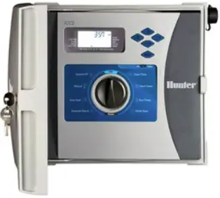
Hunter I2CF-800 Series Flow Instruction Card Instruction Manual

ICC2 FLOW INSTRUCTION CARD
12CF-800 Series Controllers include built-in flow monitoring capabilities and two sensor inputs: one dedicated for a flow sensor connection and the other for a Clik/Solar Sync sensor.
These sensor inputs wire separately across the Common terminal on the Power Module, designated by a flow icon and a weather icon.
All flow monitoring is enabled and configured at the ICC2 Controller face pack.
New Power Module
With Jumper Wire for Clik/Solar Sync only

| TERMINALS | SENSOR | |
| C | Flow Sensor Connection | |
 |
C | Clik/Solar Sync® Sensor Connection |
NOTE: All stations that will be flow monitored must have a Run Time set prior to the flow learning process. Any stations without a Run Time will not be included in the calibration.
Scan for Help ![]()

Flow Setup Menu
- Hold + button and turn dial to Pump, then release the + button to access Flow Setup menu.
- Use + and – buttons to enable flow monitoring, and select units of measure (gallons/min or liters/min).

- Press the right arrow button to configure the flow sensor.
- If the sensor is frequency/ velocity-based (i.e., Hunter HFS), input the manufacturer-specified K-Factor value. Use the + and – buttons to input the values.
- Press right arrow button to input Offset value (if applicable).
- If using a scaled-pulse type flow sensor (i.e., Hunter HC Flow Meter), press the right arrow button until “Pulse” is shown in the display.
Use the + and – buttons to input the manufacturer-specified pulse rate.
NOTE: For calibration values using Hunter flow sensors, please scan the QR code
Flow Monitor Menu
- Hold – button and turn dial to Pump, then release the – button to access the Flow Monitor menu.
- High-flow shutdown threshold can be set from 110% to 200% using the + and – buttons. This applies to each individual station.

When this threshold is exceeded, the individual station will shut down, an alarm will appear in the display, and the system will continue running the remaining stations in the program. - Low-flow shutdown threshold is accessed by pressing the right arrow button from the high-flow setup.

This also applies to each individual station and can be set from 20% to 90% using the + and – buttons. When this threshold is exceeded, the individual station will be shut down, an alarm will appear in the display, and the system will continue running the remaining stations in the program. - Press the right arrow button to access the Total Overflow setting.

Total Overflow threshold is for catastrophic high-flow shutdown, and can be set from 1 to 1,000 GPM or l/min. This alarm applies to all stations and programs, shutting down all irrigation when the maximum threshold is exceeded. - Press the right arrow button to access the Delay setting.

This can be set from 1 to 1,000 seconds and is useful in preventing false flow alarms during station startup. For the high- and low-flow alarm conditions, these have a preset 60-second delay to help with hydraulic fluctuations. You can use this additional Delay factor to confirm the flow condition is accurate. This helps any abnormal flow rates detected are persistent throughout the Delay duration and aren’t due to pump or pressure ramp up. - The last step in the Flow Monitoring setup is Station Level Flow Learning.

To access the nominal flows for each station in the system, press the right arrow button from the Delay menu. Cycle through all stations using the left and right arrow buttons to view or manually input all expected flow rates. - To enable the flow learning process, press the PRG button at any time within the Flow Monitoring menu.

This will initiate a flow reading/calibration for each individual station and takes approximately 45 to 60 seconds per station. If there are individual stations that should be left out of the flow monitoring analysis, they can be set to OFF. You can also manually input or edit the nominal flows using the + and – buttons. To cancel the flow learning process, press the PRG button again to revert to the flow monitoring menus.
Flow Reading and Alarms
To view real-time flow rates while the controller is running manual or automatic irrigation, press the PRG button on the face pack. The controller will display the flow rate for any active stations. Press the PRG button again to return to the Run screen. - “H St. # Err” = High-flow alarm detected for that station
- “L St. # Err” = Low-flow alarm detected for that station
- “FL Err” = Total overflow threshold has been exceeded

Documents / Resources
 |
Hunter I2CF-800 Series Flow Instruction Card [pdf] Instruction Manual I2CF-800 Series Flow Instruction Card, I2CF-800 Series, Flow Instruction Card, Instruction Card, Card |


