![]()
![]() X200 Input Monitor
X200 Input Monitor
Expansion Module
Installation Guide
ADC-AC-X200
ADC-AC-X200 X200 Input Monitor Expansion Module
Only compatible with HID Aero Series controllers
![]() Have you taken the Smarter Access Control training course yet?
Have you taken the Smarter Access Control training course yet?
This course is recommended for every installer and is required for three reps per Service Provider before Access Control hardware can be added to an Alarm.com account. The course should be completed at least 48 hours before the first customer installation begins. type:1_key:6dbc83b6406b4d75b5dd6550a846dede
Already familiar with Smarter Access Control? Great! You can take the Fast Track training assessment to complete the training requirement.
All training can be found here: https://academy.alarm.com/series/ access-control or by scanning the QR code above in MobileTech.
X200 Input Monitor Expansion Module
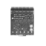
The ADC-AC-X200 expansion module provides a solution for controlling sixteen additional inputs. Two Form-C relay outputs may be used to control locking hardware or other devices. Three dedicated inputs are provided for Tamper, AC Fail, and Battery Fail. Input circuits can be configured as unsupervised or supervised using end-of-line resistors. Communication to the X1100 Door Controller is accomplished using a 2-wire RS-485 interface. The ADC-AC-X200 requires 12-24 VDC for power. See the following figure for component location.
Wiring
Connections
| TB1-1 | INPUT 1 | IN+ | INPUT 1 |
| TB1-2 | IN- | ||
| TB1-3 | INPUT 2 | IN+ | INPUT 2 |
| TB1-4 | IN- | ||
| TB1-5 | INPUT 3 | IN+ | INPUT 3 |
| TB1-6 | IN- | ||
| TB1-7 | INPUT 4 | IN+ | INPUT 4 |
| TB1-8 | IN- | ||
| TB1-9 | INPUT 5 | IN+ | INPUT 5 |
| TB1-10 | IN- | ||
| TB2-1 | INPUT 6 | IN+ | INPUT 6 |
| TB2-2 | IN- | ||
| TB2-3 | INPUT 7 | IN+ | INPUT 7 |
| TB2-4 | IN- | ||
| TB2-5 | INPUT 8 | IN+ | INPUT 8 |
| TB2-6 | IN- | ||
| TB3-1 | NOT USED | ||
| TB3-2 | RELAY 1 | NO | Relay 1 Normally Open Contact |
| TB3-3 | C | Relay 1 Common Contact | |
| TB3-4 | NC | Relay 1 Normally Closed Contact | |
| TB4-1 | INPUT 9 | IN+ | INPUT 9 |
| TB4-2 | IN- | ||
| TB4-3 | INPUT 10 | IN+ | INPUT 10 |
| TB4-4 | IN- | ||
| TB4-5 | INPUT 11 | IN+ | INPUT 11 |
| TB4-6 | IN- | ||
| TB4-7 | INPUT 12 | IN+ | INPUT 12 |
| TB4-8 | IN- | ||
| TB4-9 | INPUT 13 | IN+ | INPUT 13 |
| TB4-10 | IN- | ||
| TB5-1 | INPUT 14 | IN+ | INPUT 14 |
| TB5-2 | IN- | ||
| TB5-3 | INPUT 15 | IN+ | INPUT 15 |
| TB5-4 | IN- | ||
| TB5-5 | INPUT 16 | IN+ | INPUT 16 |
| TB5-6 | IN- | ||
| TB6-1 | NOT USED | ||
| TB6-2 | RELAY 2 | NO | Relay 2 Normally Open Contact |
| TB6-3 | C | Relay 2 Common Contact | |
| TB6-4 | NC | Relay 2 Normally Closed Contact | |
| TB7-1 | TMP | TMP+ | Tamper |
| TB7-2 | TMP- | ||
| TB7-3 | AC | AC+ | AC Fail |
| TB7-4 | AC- | ||
| TB7-5 | BT | BT+ | Battery Fail |
| TB7-6 | BT- | ||
| TB7-7 | 12-24 VDC | GND | Input Power Ground |
| TB7-8 | VIN | Input Power Ground (from local power) | |
| TB8-1 | EXPANSION IN | TR+ | IO Module Port 1 |
| TB8-2 | TR- | ||
| TB8-3 | GND | ||
| TB8-4 | EXPANSIONOUT | TR+ | IO Module Port 2 |
| TB8-5 | TR- | ||
| TB8-6 | GND | ||
| TB8-7 | 12-24 VDC | GND | Input Power Ground |
| TB8-8 | VIN | Input Power Ground (from local power) |
Status LEDs
| LED Label | Represents | Initialization | Normal Operation |
| A | ONLINE | ON then OFF | Heartbeat and Online status Offline = 1 sec rate, 20% ON Online = Blinks ON/OFF for 0.7s, ON for 0.3s |
| B | COMM | ON then OFF | Indicates communication activity on expansion module communication port |
| BAT | BATT FAIL | ON then OFF | OFF = Inactive, ON = Active, Flash = Fault* |
| AC | AC FAIL | ON then OFF | OFF = Inactive, ON = Active, Flash = Fault* |
| TMP | TAMPER | ON then OFF | OFF = Inactive, ON = Active, Flash = Fault* |
| IN1 | IN 1 | ON then OFF | OFF = Inactive, ON = Active, Flash = Fault* |
| IN2 | IN 2 | ON then OFF | OFF = Inactive, ON = Active, Flash = Fault* |
| IN3 | IN 3 | ON then OFF | OFF = Inactive, ON = Active, Flash = Fault* |
| IN4 | IN 4 | ON then OFF | OFF = Inactive, ON = Active, Flash = Fault* |
| IN5 | IN 5 | ON then OFF | OFF = Inactive, ON = Active, Flash = Fault* |
| IN6 | IN 6 | ON then OFF | OFF = Inactive, ON = Active, Flash = Fault* |
| IN7 | IN 7 | ON then OFF | OFF = Inactive, ON = Active, Flash = Fault* |
| IN8 | IN 8 | ON then OFF | OFF = Inactive, ON = Active, Flash = Fault* |
| IN9 | IN 9 | ON then OFF | OFF = Inactive, ON = Active, Flash = Fault* |
| IN10 | IN 10 | ON then OFF | OFF = Inactive, ON = Active, Flash = Fault* |
| IN11 | IN 11 | ON then OFF | OFF = Inactive, ON = Active, Flash = Fault* |
| IN12 | IN 12 | ON then OFF | OFF = Inactive, ON = Active, Flash = Fault* |
| IN13 | IN 13 | ON then OFF | OFF = Inactive, ON = Active, Flash = Fault* |
| IN14 | IN 14 | ON then OFF | OFF = Inactive, ON = Active, Flash = Fault* |
| IN15 | IN 15 | ON then OFF | OFF = Inactive, ON = Active, Flash = Fault* |
| IN16 | IN 16 | ON then OFF | OFF = Inactive, ON = Active, Flash = Fault* |
| D22 | RELAY 1 | OFF | ON = Energized |
| D23 | RELAY 2 | OFF | ON = Energized |
Communication wiring
The ADC-AC-X200 communicates to an X1100 Door Controller using a 2-wire RS-485 interface.
The ADC-AC-X200 allows for multi-drop communication on a bus of up to 4,000 feet (1,219 m). Use twisted pair (minimum 24 AWG) with drain wire and shield for communication.
If the ADC-AC-X200 is the last device on the communication bus, jumper J1 must be set to “IN”.
Note: Both Port 1 and Port 2 terminals for the Expansion Module ports are the same port and are internally connected.
RS-485 Wiring using the ADC-AC-X1100 Door Controller For ease of install, daisy chain expansion modules together. Wire each expansion module to the next module instead of wiring directly back to the controller.
Install jumpers according to the selected configuration
If there are additional downstream expansion modules, set jumper to “OUT” ∙ If this is the last device on the communication bus, set jumper to “IN”
Addressing
Flip the DIP switches on the the ADC-AC-X200 expansion module according to the “Jumpers/Switches ON” column in the Access Control Devices table on the Alarm.com Partner Portal (or MobileTech). These DIP switches are also displayed in the “Add Expansion Module” installation wizard. If these DIP switches are not set according to the Partner Portal (or MobileTech), the device and its connected readers and door hardware will not function properly with Alarm.com.
Relay Wiring
Two Form-C contact relays are provided for controlling door lock mechanisms. Each relay has a Common pole (C), a Normally Open pole (NO), and a Normally Closed pole (NC). When momentarily delivering power to unlock the locking hardware (fail secure), the Normally Open and Common poles are used. When momentarily removing power to unlock the locking hardware (failsafe), the Normally Closed and Common poles are used. Check with local building codes for proper egress door installation. 18 AWG minimum recommended for electric locking hardware.
Note: Load switching can cause abnormal contact wear and premature contact failure. Switching of inductive loads (strike) also causes EMI (electromagnetic interference), which may interfere with normal operation of other equipment.
To minimize premature contact failure and to increase system reliability, a contact protection circuit may be used. The following circuit is recommended. Locate the protection circuit as close to the load as possible (within 12 inches [30 cm]), as the effectiveness of the circuit will decrease if it is located further away.
Use sufficiently large gauge wires for the load current to avoid voltage loss.
Diode Selection
- Diode current rating: 1x strike current
- Diode breakdown voltage: 4x strike voltage
- For 12 VDC or 24 VDC strike, diode 1N4002 (100 V / 1 A) typical
Input Wiring
There are sixteen inputs that can be used to monitor door position, request-to-exit, or alarm contact devices.
Input circuits can be configured as Unsupervised (2 states):
reporting as open or closed contact, or Supervised (6 states):
reporting as open or closed contact, open circuit, shorted circuit, grounded circuit, or foreign voltage.
A supervised input circuit requires adding two resistors with value of 1k ohm, 1% to the circuit to facilitate proper reporting and should be located as close to the sensor as possible.
The input circuit wiring configurations shown are supported but may not be typical.
22 AWG minimum required for input wiring. 18 AWG recommended if wiring request-to-exit devices in series with locking hardware. Note: Either the top or bottom 12-24 V terminals can be used to power the board.
Specifications
The interface is for use in low voltage, Class 2 circuits only. The installation of this device must comply with all local fire and electrical codes.
Input power
12 to 24 VDC ±10%, 300 mA max input current
Communication
2-Wire RS-485
Inputs
16 unsupervised/supervised programmable inputs, standard EOL: 1k/1kΩ, 1%, ¼ watt One dedicated input for each:
Tamper, AC Fail, Batt Fail
Outputs
Two Form-C relay outputs: 2 A @ 30 VDC resistive
Certifications
UL 294 and UL1076 recognized
CE compliant
FCC Class A ICES-003
Dimensions (L x W x H)
6.46 × 5.51 × 1.02” (16.4 x 14.0 x 2.6 cm)
Temperature
32°F to 158°F (0°C to 70°C) (operational)
-67°F to 185°F (-55°C to 85°C) (storage)
Operating humidity
5% to 85% (non-condensing) RH
Warranty
Alarm.com warrants the product is free from defects in material and workmanship under normal use and service with proper maintenance for one year from the date of factory shipment. Alarm.com assumes no responsibility for products damaged by improper handling or installation. This warranty is limited to the repair or replacement of the defective unit.
There are no expressed warranties other than set forth herein. Alarm.com does not make, nor intends, nor does it authorize any agent or representative to make any other warranties, or implied warranties, and expressly excludes and disclaims all implied warranties of merchantability or fitness for a particular purpose. Returns must be accompanied by a Return Material Authorization (RMA) number obtained from customer service, and prepaid postage and insurance.
Liability
The Interface should only be used to control exits from areas where an alternative method for exit is available. This product is not intended for, nor is rated for operation in life-critical control applications. Alarm.com is not liable under any circumstances for loss or damage caused by or partially caused by the misapplication or malfunction of the product. Alarm com’s liability does not extend beyond the purchase price of the product.
This device complies with part 15 of the FCC Rules. Operation is subject to the following two conditions:
- This device may not cause harmful interference, and
- this device must accept any interference received, including interference that may cause undesired operation.
![]()
![]() 8281 Greensboro Drive
8281 Greensboro Drive
Suite 100
Tysons, VA 22102
210406
© 2021 Alarm.com. All rights reserved.
Designed in the USA. Made in USA.
Documents / Resources
 |
HID ADC-AC-X200 X200 Input Monitor Expansion Module [pdf] Installation Guide ADC-AC-X200 X200 Input Monitor Expansion Module, ADC-AC-X200, X200 Input Monitor Expansion Module, Monitor Expansion Module, Expansion Module |