Hi-Link HLK-LD2451 Vehicle Status Detection Module
Product Information
Specifications
- Product Name: HLK-LD2451 Vehicle Status Detection Module
- Manufacturer: Shenzhen Hi-Link Electronic Co., Ltd
- Sensing Technology: FMCW FM continuous wave radar signal processing
- Sensing Distance: Up to 100m
- Output: Speed, angle, distance, and other auxiliary information
- Output Interface: GPIO and UART
- Frequency Band: 24GHz ISM band
- Certifications: FCC and CE
Product Usage Instructions
Installation
Ensure the module is securely mounted in a location with a clear line of sight to the area where vehicle detection is required. Connect the necessary power supply and communication cables.
Configuration
Use the provided mobile software to configure parameters such as sensing distance, speed, target direction, and sensitivity according to your application requirements.
Integration
Utilize the GPIO or UART output to integrate the detection module with your desired intelligent scenes or terminal products. The plug-and-play feature allows for flexible application.
Operation
Monitor the real-time output detection results to identify vehicles close or far away from the area. Utilize the provided tools for mobile debugging and configuration as needed.
Frequently Asked Questions (FAQ)
- What is the maximum sensing distance of the HLK-LD2451 module?
The module can sense vehicles at distances of up to 100 meters. - Can the detection parameters be customized?
Yes, the mobile software provided allows for easy configuration of parameters such as sensing distance, speed, and target direction to meet specific application needs. - In which scenarios can the HLK-LD2451 module be used?
The module can be used in various scenarios including highway intersections, non-motorized roads, motorways, and smart scenes to detect vehicles and assist in various applications.
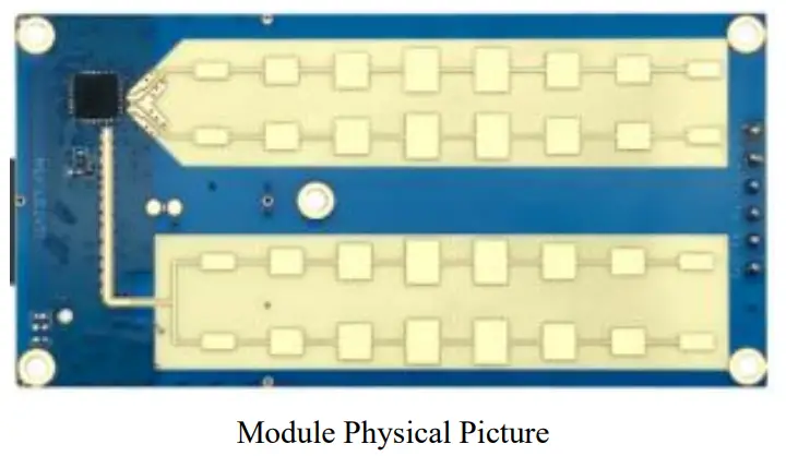
Product Profile
- HLK-LD2451 is a high-sensitivity 24GHz mobile vehicle status sensing module developed by Hi-Link Electronics. Its working principle is to use FMCW FM continuous wave to detect the target within the detection range, combined with radar signal processing, and accurate algorithm recognition, to realize high-sensitivity vehicle status detection, which can identify the vehicles close or far away, and calculate the output of the target’s speed, angle, distance and other auxiliary information.
- This product is mainly used in outdoor scenes, sensing whether there is a vehicle close to or far away from the area, real-time output detection results, and the longest sensing distance up to 100m. The longest sensing distance can be up to 100 m. Mobile software is provided to easily configure parameters such as sensing distance, speed, target direction, and sensitivity to meet different application requirements.
- Support GPIO and UART output, plug and play, can be flexibly applied to different intelligent scenes and terminal products.
Product Characteristics
- Plug and play, easy assembly method
- Sensing distance up to 100m
- Multi-level intelligent parameterization to meet the needs of scene changes
- Mobile debugging and configuration tools
- Configurable detection distance (10-100m freely adjustable)
- Wide detection angle covering up to 3 lanes of traffic
- 24GHz ISM band, FCC and CE spectrum regulation certifiable
- The Ultimate Cost-Effective Choice
Application Scenarios
HLK-LD2451 vehicle sensing module can detect and recognize vehicles close to or far away from the vehicle, supports multi-level parameterization, and can be widely used in various intelligent products and terminal products, commonly used types are as follows
- Highway intersection
Installed at highway intersections, it senses the direction of vehicles traveling on the highway as close or far away, speed, distance, etc. - Non-motorized road
Detecting the blind spot in the rear field of vision, avoiding a car accident caused by a vehicle approaching from behind and changing lanes suddenly - Motorway
Detecting distant vehicles behind, assisting the driver to determine the trajectory of the vehicle behind them - Smart Scene
Sensing the approach of vehicles, automatic control of road gates, garage doors and other scenes automatically opened or closed
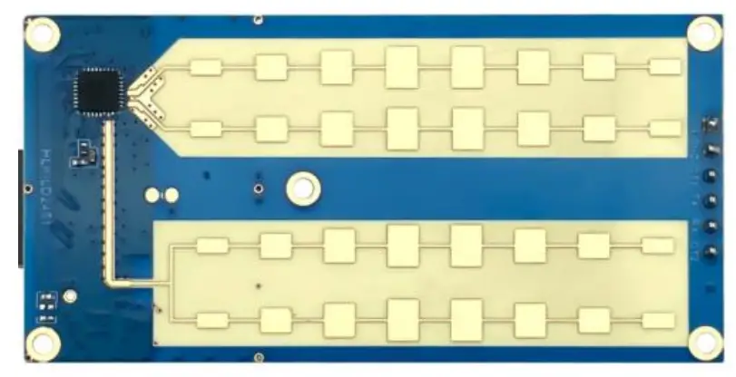
Hardware Description
External dimensions
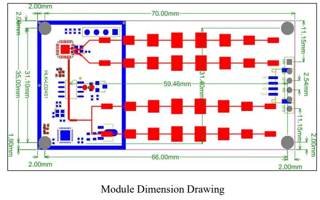
- Module size: 70mm x 35mm
- Pinhole spacing: 2.54mm
Pin Definitions

| Pin
Number |
notation | name (of a thing) | functionality |
| 1 | VIN | Power Input | Power supply input 5V |
| 2 | GND | POWER GROUND | POWER GROUND |
| 3 | OT1 | GPIO1 | Indicator pin, 3 consecutive high and low outputs on first startup Outputs high level when a person is detected approaching |
| 4 | TX | Serial TX | Serial TX Pin |
| 5 | RX | Serial port RX | Serial RX Pin |
| 6 | OT2 | GPIO2 | Temporarily unavailable |
Utilization and configuration
Typical Application Circuit
- LD2451 module mainly through the serial port by the prescribed protocol for the detection of the results of the data output, the serial port output data contains a target of the alarm information (with or without the target close) angle, distance, speed direction (close or far away) and other information, but also through the Bluetooth to accept the results of the detection of the data, the contents of the serial port part of the output and the same. Users can use it flexibly according to specific application scenarios.
- The module supply voltage is 5V, and the palace capacity of the input power supply is required to be more than 300mA.
- The module IO output level is 3.3V, the default baud rate of the serial port is 115200, 1 stop bit, no parity bit.
Role of Configuration Parameters
- Users can modify the configuration parameters to the module through the serial port of LD2451 or Bluetooth to adapt to different application requirements, and the configuration content will not be lost after power-down.
- Configurable parameters include the following:
- Maximum detection distance
- Set the farthest detection distance, only targets appearing within this farthest distance will be detected and the result will be output.
- Setting range 0~100m
- Inspection Direction
Configurable to detect only targets that are near or far and near and far.
- Maximum detection distance
- Set to close and only output the target when the vehicle traveling in the same direction approaches and meets certain conditions, set to far away and only output the target when the opposite vehicle or the surrounding environment enters the radar detection range, close and far away regardless of whether the vehicle in the same direction or in the opposite direction enters the detection range will be outputting the detected target information.
- Detection speed
- The detected target speed is greater than the set detection speed before it will be judged as having a target, otherwise, it is ignored
- Detecting speed can be set range 0~120km/h
- Detection delay
Alarm delay time after radar detects a target approaching, range 1~30s, e.g. if the time is set to 5s, if the radar detects a target approaching, it will output a delayed alarm message of 5s, and if the radar detects a target approaching again within this period, it will refresh this time. - Sensitivity
- This parameter has two sub-parameters, cumulative trigger count and signal-to-noise ratio threshold. Both word parameters can be set independently, the trigger count parameter setting range is 1~10, and the signal-to-noise ratio parameter setting range is 1~255.
- If the Trigger Count is set to 3, the detected target is triggered 3 times consecutively before the detection information of the target is reported.
- The signal-to-noise ratio parameter determines the detection sensitivity of the radar, the lower the value of the detection sensitivity the higher the trigger is sensitive, the higher the value of the detection sensitivity the lower the trigger is more difficult (the default value is 4, no special circumstances this parameter is not recommended to modify)
- Detection speed
Description of the mobile app tool
To facilitate users to quickly and efficiently test and configure the module, to provide mobile APP configuration and detection tools, users can use this tool software link module Bluetooth, the module for parameter configuration, and reading, but also can receive the module to report the detection results of the data, real-time display of the detection of the target’s information, greatly facilitating the use of the user.
- Download Address:
- Android APP download link: https://www.pgyer.com/Lq8p
- IOS APP: Search for: HLKRadarTool in the App Store App Store
- APP Usage:
- After powering up the module normally, it will send out a Bluetooth with the name “LD2451_XXXX”;
- After opening the APP to enable the corresponding permissions, click Connect Module Bluetooth;
- The detected target data information will be displayed to this interface as well as the corresponding protocol data after a successful connection;
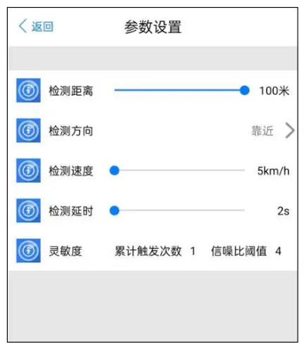
- Click on the upper right corner of the settings interface to enter the parameter setting interface, the parameters that can be set, and the role of the above “configuration parameters role”.
The APP detection data information is shown below:

Parameter setting interface:
Installation Schematic and Mounting Orientation
Installation Placement:

Installation conditions
Verify minimum mounting clearance
If the radar is to be fitted with an enclosure, the enclosure must have good wave-transmission characteristics at 24 GHz and must not contain metallic materials or materials that are shielding against electromagnetic waves.
Precautions for installation
- Ensure that the radar antenna is facing the area to be detected as much as possible and that the area around the antenna is open and unobstructed.
- Ensure that the sensor is mounted in a firm and stable position, as shaking of the radar itself will affect the detection results.
- It is important to ensure that the back of the radar is not subject to object movement or vibration. Because radar waves are penetrating, the antenna signal back flap may detect moving objects on the back of the radar. A metal shield or metal backing plate can be used to shield the radar back flap and attenuate the effect caused by objects on the back of the radar.
Performance and electrical parameters
| Operating frequency | 24GHz~24.25GHz
Complies with FCC, CE, No Commission certification standards |
| Power requirements | DC 5V, power supply capacity >300mA |
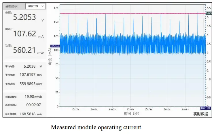
| Average operating current | 107mA |
| Modulation method | FMCW |
| Connector | 2 GPIOs, IO level 3.3V
1 UART |
| Target application | Outdoor vehicle target detection |
| Detection distance | Up to 100m |
| Detection angle | ±20° |
| Sweep bandwidth | <200MHz
Meets FCC, CE, and No Commission certification standards |
| Operating temperature | -40 ~85°C |
| Overall dimensions | 70mm x 35mm |
Revised records
| Revision date | Releases | Content of the modification |
| 2024-5-7 | 1.0 | Initial version |
Technical support and contacts
- Shenzhen Hi-Link Electronic Co., Ltd
- Address:17F,Building E, Xinghe WORLD, Minzhi Street, Long
- Hua district,Shenzhen 51813
- Email: sales@hlktech.com
- Website: www.hlktech.net
Documents / Resources
 |
Hi-Link HLK-LD2451 Vehicle Status Detection Module [pdf] User Manual HLK-LD2451 Vehicle Status Detection Module, HLK-LD2451, Vehicle Status Detection Module, Status Detection Module, Detection Module, Module |