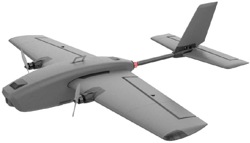
HEE WING T-1 VTOL FPV Plane
Product Information
Specifications:
- Model: FX-405 Flight Controller
- Compatibility: T1 Ranger RC Plane
- Receiver Compatibility: SBUS, CRSF, ELRS
Product Usage Instructions
Setting Up the Flight Controller:
- Remove all contents from the box and locate the provided USB wires.
- Connect your preferred receiver to the RC-In port of the FX-405 Flight Controller, noting the Ground, 5V & Signal lines.
- Turn on your radio and connect the battery to your T1 Ranger.
- Connect the USB cable provided to the flight controller’s USB port and the other end to your PC.
- Open the Mission Planner software on your PC and select the correct COM port.
- Click Connect to establish a connection with the flight controller.
SBUS Receiver Setup:
- Click CONFIG and then Full Parameter List in Mission Planner.
- Type BRD_ALT_CONFIG in the search box, change the value to 0, and write the changes to the flight controller.
- Type SERIAL6_PROTOCOL in the search box, change the value to -1, and write the changes.
- Click Disconnect, unplug the USB cable, and disconnect the battery before reconnecting.
Radio Calibration:
- Turn on the radio, connect the battery, and USB to the flight controller and PC.
- In Mission Planner, click Setup, then Mandatory Hardware, and Radio Calibration.
- Follow on-screen instructions to calibrate your radio inputs/stick values.
- Click when Done to complete calibration.
Assembly of the Plane:
- Gather tail boom, stabilizers, guide wire, screws, and a screwdriver.
- Pull the servo connector through the tail boom using the guide wire.
FAQs
- Q: How do I know if my SBUS setup is working?
A: After completing the SBUS receiver setup steps, reconnect the battery. If SBUS is working properly, you should see successful communication between your radio and the flight controller. - Q: Do I need to perform receiver setup for CRSF or ELRS receivers?
A: No, Ardupilot automatically recognizes Crossfire (CRSF) or ELRS input. You only need to follow receiver setup steps if you are using an SBUS receiver.
Package Content

Remove the content out of the box including the provided USB wires for the Flight Controller. Also, prepare your radio, receiver and battery.
Product Instruction
Connect your preferred receiver to the RC-In port of the FX-405 Flight Controller.
*Note the Ground, 5V & Signal line.
Turn on your radio and hook up battery to your T1 Ranger.
Then connect the USB cable provided to the flight controller’s USB port and the other end to your PC.
Open the Mission Planner software on your pc. If you do not have one yet, visit our website for the download link here > https://www.heewing.com/pages/fx-405-vtol-flight-controller
On the top right of the window, select the correct COM port. *every PC has a different COM number, it will be a different COM number on your PC.
Then click Connect.
After successfully connecting to the flight controller, please ignore any errors and proceed to next step.
Note: Ardupilot automatically recognizes Crossfire or ELRS input, you do not need to perform receiver setup if you are using Crossfire or ELRS receiver. For SBUS receiver, please follow steps below.
Setting up of the receiver
- Click CONFIG on the top left of the screen.

- Click Full Parameter List on the left menu.

- On the Search box on the right side, type BRD_ALT_CONFIG.

- The corresponding parameter will be displayed.

- Change the “Value” from “1” to “0”, then click “Write Params” to write the changes to the flight controller. Click “Ok” to confirm.

- Again, on the Search box, type SERIAL6_PROTOCOL The corresponding parameter will be displayed.

- Change the “Value” from “23” to “-1”. Click “Write Params”, then click “Ok”.
Congratulation! You are done!
Below are the relevant parameters for your reference. Please make sure it’s correct.
- SBUS receiver setup: BRD_ALT_CONFIG = 0 ; SERIAL6_PROTOCOL = -1
- CRSF/ELRS receiver setup: BRD_ALT_CONFIG = 1 ; SERIAL6_PROTOCOL = 23
IMPORTANT, after the above is completed, before we proceed to next step, click “Disconnect” on the top right of the screen > disconnect the USB cable from the Flight controller and the PC > disconnect the battery.
When you connect the battery again, SBUS should be working now.
Radio Calibration
- Turn on the radio, connect battery to your T1 Ranger, connect USB to the flight controller and your PC.
Then open Mission Planner and click Setup.
- Click “Mandatory Hardware” on the top left.

- Click “Radio Calibration”.

- Click “Radio Calibration” as shown in the picture below.

- Follow the instructions as shown on the screen. Click OK.

- Click OK and perform the instructions as shown. Move all your control sticks and flight modes switches to their max.

- Click OK. Now observe Mission Planner recognizing the new inputs/stick values of your own radio.

- When you are done, click “Click when Done”.

- Follow the instructions shown and click OK.

- Mission Planner now displays the MIN and MAX of the PWM values of your Radio. Click OK again.

- It will then display “Completed”.

- You have completed the Ardupilot/Mission Planner setup.
Assembly of the plane
- a. Prepare the tail boom, horizontal stabilizer, vertical stabilizer, guide wire, 2×20 screw, 2×6 screw and a Philips screwdriver.

- b. Using the provided guide wire, pull the servo connector through from one end of the tail boom to the other end of the tail boom.

Tips: using the U shape of the wire and clip it onto the servo connector.
Gently pull the servo connector through the tail boom to the other end as shown.
- c. Observe the U Shape cut on the tail boom and align it to the stop inside the horizontal stabilizer mount.

- d. After inserting the tail boom, ensure the U-shaped cut is centered and is not pushing onto any wires. If installed correctly, the hole is clearly see through and the servo wire is visible as well.

- e. Align the vertical stabilizer onto the clip of the horizontal stabilizer as shown below and install it.


- f. Rotate to the other side and install the corresponding screws according to the marking on the mount.


- g. Now let’s assemble our completed tail onto the main fuselage. This is to be secured with the provided nut.

- h. Slot the red color nut onto the tail boom first, and observe the direction as shown below.

- I. Slot in the wires into the fuselage together with the tail boom and secure it with the nut. Do not need to over tighten the nut as long as it’s not loose.

- j. Connect the elevator servo into S2 port on the flight controller. Observe the Ground, 5V & Signal orientation.

- k. Now connect the 3 motor wires together. Just follow the color of the wire ie black to black, red to red and orange to orange.

- l. Now we are gonna install the battery mount. Prepare the battery mount, fuselage, battery strap, 2×6 screw and screwdriver.

- m. Slot the battery strap through the battery mount, organize the wires to one side to prevent the wires getting squashed.

- n. Place the battery mount onto the wooden rail, align the screw holes and secure it with 4pcs of 2×6 screw.

- o. Now let’s install the Control Horns.

- p. After installing the steel linkage into the latch, place it in the opening of a vernier caliper, the end-to-end length should be 46mm. If you do not have a vernier caliper, you may use a ruler. Repeat the same thing for the other 2 linkages.

- q. On the main wing, install the control horn through the slit of the control surface and secure it with the latch.

- r. Slot the steel linkage into the hole on the servo horn that is furthest away from the center, then secure the other end onto the control horn.

- s. The servo horn angle should be parallel to the wing surface. With the servo centered(best when it’s powered), you may adjust the linkage length accordingly to ensure that the control surface is align with the wing surface as shown on the 2nd photo.

- t. Install the control horn onto the elevator and secure it with the latch.

- u. Install the linkage the same way as on the main wing previously.

- v. Ensure that the elevator is parallel to the horizontal stabilizer by adjusting the linkage length.

- x. Installing wings onto the main body/fuselage.

- y. Slot the carbon rod into the main wing.

- z. Carefully attach the main wing onto the fuselage and ensure that it’s properly clipped onto.
*Do not attach or detach the main wing while it’s powered as this can damage the electronics.
- ab. Installing the latch of the canopy.

- ac. Slot the latch through the canopy and secure it with the clip. The flat side of the clip facing outside.

- ad. Slide the smaller rear canopy towards the rear of the fuselage and ensure no wire between the canopy and the carbon rod.

- ae. Now slide the canopy with the hatch towards the front, gently press the latch onto the carbon rod to secure it onto the fuselage.

- af. Installing the propellers.

- ag. Prepare your propellers, 2×8 screws and an allen key.

- ah. Secure the propeller onto the motor with the screws. Observe the orientation of the propeller.

- ai. Rotation of left and right side of the propeller.

- aj. The build is completed! You may install the decal or the landing gear according to your personal preference.

Documents / Resources
 |
HEE WING T-1 VTOL FPV Plane [pdf] Instruction Manual FX-405, T-1 VTOL FPV Plane, T-1 VTOL, FPV Plane, Plane |