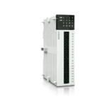
S08AO2-E PLC Analog Module
Haiwell PLC User Manual
Classic Programmable Logic Controller
Analog Module User Manual & Application Case

Xiamen Haiwell Technology Co., Ltd. www.haiwell.com
www.haiwell.com
Haiwell PLC – Analog Module User Manual & Application Case
Analog Module User Manual
1. Product Model List and Dimension
Ethernet Model 24VDC Ethernet Model 220VAC
| Ethernet Model | 24VDC | Ethernet Model | 220VAC | Model | 24VDC | Model | 220VAC | Dimension |
| S04AI | 0.07A | S04AI2 | 7W |
70×95×82mm
|
||||
| S04AO | 0.15A | S04AO2 | 8.8W | |||||
| S04XA | 0.1A | S04XA2 | 7.8W | |||||
| S08AI-e | 0.11A | S08AI2-e | 7.9W | S08AI | 0.08A | S08AI2 | 7.3W |
93×95×82mm
|
| S08AO-e | 0.25A | S08AO2-e | 12.4W | S08AO | 0.22A | S08AO2 | 11.8W | |
| S08XA-e | 0.18A | S08XA2-e | 10.4W | S08XA | 0.15A | S08XA2 | 9.8W |

- Fixed hole
- Removable terminal screw
- Terminal definition
- Module expansion port
- DIP switch4-channel module without DIP switch
- External power supply terminal (DC24V and AC220V, Generally powered by the host PLC)
- Guide rail buckle
- Removable terminal
- Analog input channel indicator
- RS485 communication port
- PWR power indicator, LINK module communication indicator
- Module expansion port
- Transparent cover of module terminal
- Module nameplate
- 35mm DIN guide rail
2. Indicator Description
- PWR: power indicator. green, constant light -Power normal; Not light – Power abnormal.
- LINK: multi-status indicator . three colors (Red. Yellow. Green), as follow:
| Reference processing mode | Module bus state |
LINK indicator state
|
|
Normal
|
No communication of module | No light |
| MPU has identified the module but no communication |
Constant light in green
|
|
| Serial or parallel port in communication |
Green jitter: indicator on 30ms and off 30ms
|
|
|
Parallel power supply not
enough, must connect to external power supply |
Without serial or parallel port in communication |
Yellow flicker: indicator on 0.5s and off 0.5s
|
| With serial or parallel port in communication |
Yellow is darkened and jitter alternately: indicator off 0.5s and
jitter 0.5s |
|
|
Firmware upgrade failed,
reupgrade the module firmware |
Without serial or parallel port in communication |
Red flicker: indicator on 0.5s and off 0.5s
|
| With serial or parallel port in communication |
Red is darkened and jitter alternately: indicator off 0.5s and
jitter 0.5s |
|
|
Hardware failure and
maintenance |
Without serial or parallel port in communication |
Constant light in red
|
| With serial or parallel port in communication |
Red jitter quickly: indicator on 30ms and off 30ms
|
3 RJ45 Ethernet indicator: there are two Ethernet LEDs, green and yellow, as shown on the picture:
Color
Green light is long bright Green light goes out
Yellow light blinks
Yellow light goes out
Status description
Physical connection of TCP module and external device is normal;
TCP module fails to connect with external device or the module itself is abnormal TCP module is connected to an external device normally, and blinking frequency indicates the data transmission speed. When speed is fast, human eye is not easy to distinguish, at this time, yellow light is long bright. No data transmission communication of TCP module and external device
3. Power Supply Specification
Item Power supply voltage Power supply frequency Instantaneous surge Power loss time Fuse 24V Output voltage (for input and expansion)
Isolation Type
Power Protection
DC Power Supply 24VDC -15%~+20% —- MAX 20A 1.5ms @24VDC 10ms or less 0.3A, 250V None
No Electrical isolation
DC input power polarity reverse, over voltage protection
AC Power Supply 100~240VAC 50~60Hz 20A 1.5ms MAX @220VAC 20ms or less @220VAC 2A, 250V 24V, -15%~+15%, 200mA (Max) Transformer isolation or optoelectronic isolation,1500VAC/1 minute
DC 24V output over current protection
4. Environmental Specifications for Product
Item Temperature/Humidity Vibration Resistance Impact Resistance Interference Immunity Over Voltage Resistance Insulation Impedance Operating environment
Environment Specification Operating temperature:0~+55 Storage temperature:-25~+70 Humidity: 5~95%RH, No condensation 10~57 HZ, amplitude=0.075mm, 57HZ~150HZ acceleration=1G, 10 times each for X-axis, Y-axis and Z-axis 15G, duration=11ms, 6 times each for X-axis, Y-axis and Z-axis DC EFT:±2500V Surge:±1000V 1500VAC/1min between AC terminal and PE terminal, 500VAC/1min between DC terminal and PE terminal Between AC terminal and PE terminal @500VDC,>=5M ,all input/output points to PE terminal @500VDC Avoid dust, moisture, corrosion, electric shock and external shocks
5. Analog Input (AI) Specification
Item Input range Resolution Input impedance
Maximum input range
Input indication Response time Digital input range Precision Power supply Isolation mode Power consumption
Voltage input
Current input
0V~+10V
0V~+5V
1V~+5V
0~20mA 4~20mA
2.5mV
1.25mV
1.25mV
5A
6M
250
±13V
±30mA
LED light ON means normal ,OFF means external disconnect
5ms/4 Channel
12 bits,Code range:0~32000(H series module 16 bits A/D convert)
0.2% F.S
MPU use internal power supply, extend module use external power supply 24VDC ±10% 5VA
Optoelectronic isolation,Non-isolation between Channels, between analog and digital is optoelectronic isolation
24VDC ±20%,100mA(maximum)
6. Analog Output (AQ) Specification
Item Output range Resolution Output load impedance Output indication Drive capability Response time Digital output range Precision Power supply Isolation mode Power consumption
| Item | Voltage output | Current output | |||
| Output range | 0V~ +10V | 0V~+5V | 1V~+5V | 0~20mA | 4~20mA |
| Resolution | 2.5mV | 1.25mV | 1.25mV | 5uA | 5uA |
| Output load impedance | 1KΩ@10V | ≥500Ω@10V | ≤500Ω | ||
| Output indication | LED ON means normal | ||||
| Drive capability | 10mA | ||||
| Response time | 3ms | ||||
| Digital output range | 12 bits,Code range:0~32000(H series module 16 bits D/A convert) | ||||
| Precision | 0.2% F.S | ||||
| Power supply | MPU use internal power supply, expansion modules use external power supply 24VDC ±10% 5VA | ||||
| Isolation mode | Optoelectronic isolation,Non-isolation between Channels ,between analog and digital is optoelectronic isolation | ||||
| Power consumption | 24VDC ±20%,100mA(maximum) | ||||
7. Analog Input (AI) Wiring Diagram

8. Analog Output (AQ) Wiring Diagram

9. MPU Terminal Wiring Diagram


10. Module Parameter Table
(CR code is corresponding to the Modbus register address)
4-channel analog module parameter table Note: CR code is corresponding to the Modbus register address, the ray parts are read-only ,the white parts are readable and writable.
|
CR |
code Function description |
||
|
S04AI |
S04AO |
S04XA |
|
|
00H |
Low byte for module code, and high byte for module version number. |
||
|
01H |
Communication address |
||
|
02H |
Communication protocol: The low 4-bit of the low byte: 0 – N,8,2 For RTU, 1 – E,8,1 For RTU, 2 – O,8,1 For RTU, 3 – N,7,2 For ASCII, 4-E,7,1 For ASCII, 5 – O,7,1 For ASCII, 6 – N,8, 1 For RTU The high 4-bit of the low byte: 0 – 2400, 1 – 4800, 2 – 9600, 3 – 19200, 4 – 38400, 5 – 57600, 6 – 115200 |
||
|
03H~06H |
Module name |
||
|
07H~08H |
Default IP address: 192.168.1.111 |
||
|
09~0AH |
Reserve |
||
|
0BH |
High byte subnet mask (b3~b0,1 indicates 255, 0 indicates 0, for example subnet mask 255.255.255.0, b3~b0=1110), lowbyte |
||
|
0CH-0EH |
Reserve |
||
|
0FH |
Error code: 0-Normal, 1-Illegal firmware identity, 2-Incomplete firmware, 3-System data access exception, 4-No external 24Vpowersupply |
||
|
10H |
channel 1 input value |
channel 1 output value |
input channel 1 input value |
|
11H |
channel 2 input value |
channel 2 output value |
input channel 2 input value |
|
12H |
channel 3 input value |
channel 3 output value |
input channel 1 signal type, note 2 |
|
13H |
channel 4 input value |
channel 4 output value |
input channel 2 signal type, note 2 |
|
14H |
channel 1 signal type, note 2 |
channel 1 signal type, note 2 |
Use the engineering value mark, note 6 |
|
15H |
channel 2 signal type, note 2 |
channel 2 signal type, note 2 |
input channel 1 engineering lower limitingvalue |
|
16H |
channel 3 signal type, note 2 |
channel 3 signal type, note 2 |
input channel 2 engineering lower limitingvalue |
|
17H |
channel 4 signal type, note 2 |
channel 4 signal type, note 2 |
input channel 1 engineering upper limitingvalue |
|
18H |
Use the engineering value mark, note |
6 Use the engineering value mark, note |
6 input channel 2 engineering upper limitingvalue |
|
19H |
channel 1 engineering lower limitingvalue |
channel 1 engineering lower limitingvalue |
input channel 1 sampling frequency, note1 |
|
1AH |
channel 2 engineering lower limitingvalue |
channel 2 engineering lower limitingvalue |
input channel 2 sampling frequency, note1 |
|
1BH |
channel 3 engineering lower limitingvalue |
channel 3 engineering lower limitingvalue |
input channel 1 zero point correction value |
|
1CH |
channel 4 engineering lower limitingvalue |
channel 4 engineering lower limitingvalue |
input channel 2 zero point correction value |
|
1DH |
channel 1 engineering upper limitingvalue |
channel 1 engineering upper limitingvalue |
Channel 1~2 input disconnection alarm, note5 |
|
1EH |
channel 2 engineering upper limitingvalue |
channel 2 engineering upper limitingvalue |
output channel 1 output value |
|
1FH |
channel 3 engineering upper limitingvalue |
channel 3 engineering upper limitingvalue |
output channel 2 output value |
|
20H |
channel 4 engineering upper limitingvalue |
channel 4 engineering upper limitingvalue |
output channel 1 signal type, note 2 |
|
21H |
channel 1 sampling frequency, note |
1 power-off output mark, note 8 |
output channel 2 signal type, note 2 |
|
22H |
channel 2 sampling frequency, note |
1 channel 1 power-off output value |
Use the engineering value mark, note 6 |
|
23H |
channel 3 sampling frequency, note |
1 channel 2 power-off output value |
output channel 1 engineering lower limitingvalue |
|
24H |
Channel 4 sampling frequency, note |
1 channel 3 power-off output value |
output channel 2 engineering lower limitingvalue |
|
25H |
channel 1 zero point correction |
value channel 4 power-off output value |
output channel 1 engineering upper limitingvalue |
|
26H |
channel 2 zero point correction |
value Channel indicator status, note |
7 output channel 2 engineering upper limitingvalue |
|
27H |
channel 3 zero point correction |
value Reserve |
power-off output mark, note 8 |
|
28H |
channel 4 zero point correction |
value |
output channel 1 power-off output value |
|
29H |
Channel 1~4 input disconnectionalarm, note 5 |
|
output channel 2 power-off output value |
|
2AH |
Reserve |
|
output channel indicator, note 7 |
|
2BH~2FH |
|
|
Reserve |
8-channel analog module parameter table
Note: CR code is corresponding to the Modbus register address, the gray parts are read-only, the white parts are readableandwritable.
|
CR |
code Function description |
||
|
S08AI |
S08AO |
S08XA |
|
|
00H |
Low byte for module code, and high byte for module version number. |
||
|
01H |
Communication address |
||
|
02H |
Communication protocol: The low 4-bit of the low byte: 0 – N,8,2 For RTU, 1 – E,8,1 For RTU, 2 – O,8,1 For RTU, 3 – N,7,2 For ASCII, 4-E,7,1 For ASCII, 5 – O,7,1 For ASCII, 6 – N,8, 1 For RTU The high 4-bit of the low bytes: 0 – 2400, 1 – 4800, 2 – 9600, 3 – 19200, 4 – 38400, 5 – 57600, 6 – 115200 |
||
|
03H~06H |
Module name |
||
|
07H~08H |
Default IP address: 192.168.1.111 |
||
|
09~0AH |
Reserve |
||
|
0BH |
High byte subnet mask(b3~b0,1 indicates 255,0 indicates 0 , for example, subnet mask 255.255.255.0, b3~b0=1110), lowbyte |
||
|
0CH~0EH |
Reserve |
||
|
0FH |
Error code: 0-Normal, 1-Illegally firmware identity, 2-Incomplete firmware, 3-System data access exception, 4-No external 24Vpowersupply |
||
|
10H |
channel 1 input value |
channel 1 output value |
input channel 1 input value |
Reserved
6 / 18
www.haiwell.com Haiwell PLC – Analog Module User Manual
|
CR |
code Function description |
||
|
S08AI |
S08AO |
S08XA |
|
|
11H |
channel 2 input value |
channel 2 output value |
input channel 2 input value |
|
12H |
channel 3 input value |
channel 3 output value |
input channel 3 input value |
|
13H |
channel 4 input value |
channel 4 output value |
input channel 4 input value |
|
14H |
channel 5 input value |
channel 5 output value |
input channel 1 signal type, note 2 |
|
15H |
channel 6 input value |
channel 6 output value |
input channel 2 signal type, note 2 |
|
16H |
channel 7 input value |
channel 7 output value |
input channel 3 signal type, note 2 |
|
17H |
channel 8 input value |
channel 8 output value |
input channel 4 signal type, note 2 |
|
18H |
channel 1 signal type, note 2 |
channel 1 signal type, note 2 |
Use the engineering value mark, note 6 |
|
19H |
channel 2 signal type, note 2 |
channel 2 signal type, note 2 |
input channel 1 engineering lower limiting value |
|
1AH |
channel 3 signal type, note 2 |
channel 3 signal type, note 2 |
input channel 2 engineering lower limiting value |
|
1BH |
channel 4 signal type, note 2 |
channel 4 signal type, note 2 |
input channel 3 engineering lower limiting value |
|
1CH |
channel 5 signal type, note 2 |
channel 5 signal type, note 2 |
input channel 4 engineering lower limiting value |
|
1DH |
channel 6 signal type, note 2 |
channel 6 signal type, note 2 |
input channel 1 engineering upper limiting value |
|
1EH |
channel 7 signal type, note 2 |
channel 7 signal type, note 2 |
input channel 2 engineering upper limiting value |
|
1FH |
channel 8 signal type, note 2 |
channel 8 signal type, note 2 |
input channel 3 engineering upper limiting value |
|
20H |
Use the engineering value mark, note |
6 Use the engineering value mark, note |
6 input channel 4 engineering upper limiting value |
|
21H |
channel 1 engineering lower limiting value |
channel 1 engineering lower limiting value |
input channel 1 sampling frequency, note1 |
|
22H |
channel 2 engineering lower limiting value |
channel 2 engineering lower limiting value |
input channel 2 sampling frequency, note1 |
|
23H |
channel 3 engineering lower limiting value |
channel 3 engineering lower limiting value |
input channel 3 sampling frequency, note1 |
|
24H |
channel 4 engineering lower limiting value |
channel 4 engineering lower limiting value |
input channel 4 sampling frequency, note1 |
|
25H |
channel 5 engineering lower limiting value |
channel 5 engineering lower limiting value |
input channel 1 zero point correction value |
|
26H |
channel 6 engineering lower limiting value |
channel 6 engineering lower limiting value |
input channel 2 zero point correction value |
|
27H |
channel 7 engineering lower limiting value |
channel 7 engineering lower limiting value |
input channel 3 zero point correction value |
|
28H |
channel 8 engineering lower limiting value |
channel 8 engineering lower limiting value |
input channel 4 zero point correction value |
|
29H |
channel 1 engineering upper limiting value |
channel 1 engineering upper limiting value |
Channel 1~4 input disconnection alarm, note5 |
|
2AH |
channel 2 engineering upper limiting value |
channel 2 engineering upper limiting value |
output channel 1 output value |
|
2BH |
channel 3 engineering upper limiting value |
channel 3 engineering upper limiting value |
output channel 2 output value |
|
2CH |
channel 4 engineering upper limiting value |
channel 4 engineering upper limiting value |
output channel 3 output value |
|
2DH |
channel 5 engineering upper limiting value |
channel 5 engineering upper limiting value |
output channel 4 output value |
|
2EH |
channel 6 engineering upper limiting value |
channel 6 engineering upper limiting value |
output channel 1 signal type, note 2 |
|
2FH |
channel 7 engineering upper limiting value |
channel 7 engineering upper limiting value |
output channel 2 signal type, note 2 |
|
30H |
channel 8 engineering upper limiting value |
channel 8 engineering upper limiting value |
output channel 3 signal type, note 2 |
|
31H |
channel 1 sampling frequency, note |
1 power-off output mark, note 8 |
output channel 4 signal type, note 2 |
|
32H |
channel 2 sampling frequency, note |
1 channel 1 power-off output value |
Use the engineering value mark, note 6 |
|
33H |
channel 3 sampling frequency, note |
1 channel 2 power-off output value |
output channel 1 engineering lower limitingvalue |
|
34H |
channel 4 sampling frequency, note |
1 channel 3 power-off output value |
output channel 2 engineering lower limitingvalue |
|
35H |
channel 5 sampling frequency, note |
1 channel 4 power-off output value |
output channel 3 engineering lower limitingvalue |
|
36H |
channel 6 sampling frequency, note |
1 channel 5 power-off output value |
output channel 4 engineering lower limitingvalue |
|
37H |
channel 7 sampling frequency, note |
1 channel 6 power-off output value |
output channel 1 engineering upper limitingvalue |
|
38H |
channel 8 sampling frequency, note |
1 channel 7 power-off output value |
output channel 2 engineering upper limitingvalue |
|
39H |
channel 1 zero point correction |
value channel 8 power-off output value |
output channel 3 engineering upper limitingvalue |
|
3AH |
channel 2 zero point correction |
value Channel indicator status, note |
7 output channel 4 engineering upper limitingvalue |
|
3BH |
channel 3 zero point correction |
value Reserve |
power-off output mark, note 8 |
|
3CH |
channel 4 zero point correction |
value |
output channel 1 power-off output value |
|
3DH |
channel 5 zero point correction |
value |
output channel 2 power-off output value |
|
3EH |
channel 6 zero point correction |
value |
output channel 3 power-off output value |
|
3FH |
channel 7 zero point correction |
value |
output channel 4 power-off output value |
|
40H |
channel 8 zero point correction |
value |
output channel indicator, note 7 |
|
41H |
Channel 1~8 input disconnectionnote 5 |
alarm, |
Reserve |
|
42H~4FH |
Reserve |
|
|
Note:
1. Sampling frequency:0 – 2 times, 1 – 4 times, 2 – 8 times, 3 – 16 times, 4 – 32 times, 5 – 64 times, 6 – 128 times, 7- 256times2. Signal type: 0 – [4,20]mA, 1 – [0,20]mA, 2 – [1,5]V, 3 – [0,5]V, 4 – [0,10]V
3. Disconnection alarm:Each bit indicates 1 channel, 0-normal, 1-disconnection
4. Use the engineering value mark:Each bit indicates 1 channel, 0-No, 1-Yes
5. Channel indicator status:Each bit indicates 1 channel, 0-off, 1-on
6. Power-off output mark:Each bit indicates 1 channel, 0-No, 1-Yes
11. Mounting and installation
The PLC should be secured to an enclosed cabinet while mounting. For heat dissipation, make sure to provide a minimum clearance of 50mm between the unit and all sides of the cabinet. (See the figure.)
Rail Mounting: Use standard 35 mm rail.
Screw Mounting: Each MPU or expansion module has two positioning screw holes, the diameter of the hole is 4.5mm. Please refer to the dimension figure for the location of the positioning holes and their spacing. To avoid over temperature and for a better heat dissipation, do not mount PLC to a position near to the bottom/top of the cabinet. Do not mount PLC in vertical direction.
Expansion Module Wiring: Connections between expansion modules and connections between module and MPU are achieved through bus. One expansion cable will be configured to every expansion module, for the connection between two different modules.Connection methods: turn the right side of extended interface(the last MPU or expansion module) over, plug the expansion cable in the extended interface, then press down the cover of the extended interface to reset the interface, the extended interface at the right side of the module will be reserved for expansion of the next module. Connect all expansion modules in turn in the same way.

www.haiwell.com
Haiwell PLC – Analog Module Application Case
Analog Module Application Case
1. Expand module through the host PLC parallel port
1.1. Module power supply
Analog module can be the expansion module for any host PLC; When the module is directly hung behind the host PLC by parallel bus, no need to take external power supply, the module is powered by host PLC’ parallel port, if the power supply of module is insufficient (the PWR power indicator does not light), then according to different models, the module can be powered by 24VDC or 220VAC. When the module is extended through the parallel port, it is recommended to use 24VDC module. Module power supply example:
1 When the host PLC can be expanded to 7 modules, the PWR indicators of frist five modules are long bright, indicating the modules power supply are normal, and if the PWR indicators of the 6th and 7th modules are not light, appearing insufficient power supply, as long as the 6th and 7th modules are taken external power supply.
2 When the host PLC with 1 expansion module, because the host PLC provides power supply through the parallel port, the PWR indicator of modue will light; If the module is added external power supply, it can still work, this time the module will automatically determine and give priority to external power supply.
1.2. The analog need’t be written any conversion program, read the analog register value directly.
For example, the host PLC T16S2T, respectively, is expanded with three modules of S04AI, S04AO and S08XA through the parallel port from left to right, assuming the scene:
- Analog module S04AI input channel 1, signal type is 4-20mA, used to measure the pressure, the pressure range of 0.0~3.0Mpa;
- Analog module S04AO input channel 1, signal type is 0-10V, used to control the inverter frequency of 0.0~50.0Hz;
First enter the PLC programming software menu bar – view – hardware configuration, in accordance with the external order of actual modules to add the module models, after added, the analog address will be automatically arranged, as shown below:

Haiwell analog module need’t be written any conversion program, as for above pressure measurement, we only need to check the use of engineering value, set the lower limit value of 0 corresponding 0.0Mpa, set the upper limit value of 3000 indicating 3.000Mpa, the upper limit value 3000 hidden three decimal places can achieve magnification times and improve accuracy. Then we read the value of the analog input register AI0, if AI0 = 1234, then the actual value is 1.234Mpa.

Similarly, for the analog output, check the use of engineering value, set the lower limit value of 0 indicating 0.0Hz, set the upper limit value of 500 indicating 50.0Hz, if you want the inverter frequency output is 25.6Hz, as long as force the AQ0 value as 256 or through other logic instructions to output the AQ0 value of 256. As shown below:

1.3. Programming skills
If you want to write the alarm program that pressure exceeds the setting value,for example, when the pressure is more than 1.25Mpa, it will alarm, the program of PLC can be written as follows:
 1.4. Display analog value on SCADA, HMI
If the configuration, touch screen, text and other PC software want to display the current pressure, only need to set three decimal places on the numerical display primitive, then the read value will be automatically reduced 1000 times in the configuration, that is the actual temperature value, for example, you can set 3 on decimal places of Haiwell Cloud SCADA settings.
So that when the PLC read AI0 value, AI0=1234, that is the actual value of 1.234Mpa, there is no need to have data processing in PLC and configuration, only set the 3 decimal places on the numerical display primitive, then it will be automatically reduced by 1000 times, displaying value of 1.234, that is the actual value of 1.234Mpa.
1.5. When the engineering value is not used, the default code value is 0 ~ 32000
When using the engineering value, the linear transformation is specified by the lower limit and the upper limit value, and the program is automatically transformed. When the engineering value is not used, all types are unified to correspond with 0 ~ 32000 code value. The same case of pressure measurement, this time can according to the linear transformation formula: Out = (In – InDw) * (OutUp- OutDw) / (InUp- InDw) + OutDw to write the conversion program, or use the SC linear transformation instructions to calculate directly.
Haiwell analog used easily, it is recommended to check the use of engineering value, so that the analog will be very convenient without writing any program.
1.6. Module CR code application example: Read the module channel disconnection alarm
In this example, in order to read the external sensor disconnection information of S08XA module, the disconnection alarm data of S08XA module input channel 1-4 is stored in CR29, that is, 29H (hexadecimal), decimal 41. (More CR contents can be found in the software online help – hardware manual – expansion module parameters within the corresponding model). This program is as follows:
Slot: Position number, S08XA is the third module, so fill in 3; CR: Module disconnection alarm CR41, that is, 29H (hexadecimal) = 41 (decimal), it can be directly input 41 or 0x29 into the instruction CR terminal; N: Number for readings, 1 register for 16 bits, low 4 bits corresponding channel 1-4, disconnection for 1 (ON), normal for 0 (OFF).
2. Module used as remote IO
Haiwell PLC expansion module is built-in one RS485 communication port(Some models with Ethernet communication port), which not only supports parallel bus(Use the expansion bus to connect with the parallel interface of host PLC), but also supports serial bus(Use the RS485 communication port of module networking with communication port of host PLC, and host PLC controls the remote module by communication instructions), when using the serial bus to expand (that is, remote IO module), it doesn’t have expansion limit of system points and can be distributed installation.
Distributed installation is very important for the system which needs to collect and monitor a large number of decentralized digital or analog signals(temperature, humidity, differential pressure, blowing rate, flow, fan speed, valve opening, etc.), it can easily achieve distributed installation control and unlimited points of expansion, greatly improving the control system configuration flexibility and future control expansion capabilities, reducing the number of signal wiring, also reducing the interference problem of too long analog signal line, saving the project investment costs.
The following will introduce the operation key points and techniques.
2.1. Module power supply
When the module is used as remote IO, there are two optional models of 24VDC and 220VAC, such as S08AI model for the DC 24V power supply. S08AI2 for AC 220V power supply. If the module is powered normally, the PWR indicator will light.
2.2. Communication port introduction 1
All analog modules are built-in RS485 port. 2 As for 8-point analog module, you can choose the Ethernet port. 3 RS485 communication port and Ethernet port can be used at the same time, for example, the RS485 of module communicates with PLC, Ethernet port can also communicates with multiple host computers (up to 7).
2.3. Communication protocols and default parameters RS485:
Support standard Modbus RTU / ASCII protocol, it can communicate with the configuration, touch screen, text, PLC and other third-party host computer, which must support Modbus protocol. Among them: Address: 1 ~ 254 can be set; module address is divided into soft address and hard address, hard address has the highest
priority. Soft address: The address set through programming software – remote tool, address range 1-254; Hard address: The address set through the 4-bit DIP switch of module hardware, address range 1-15. Hardware address
setting example:
Baud rate: 2400, 4800, 9600, 19200, 38400, 57600, 115200 optional; Data format : N, 8, 2 RTU, E, 8, 1 RTU, O, 8, 1 RTU, N, 8, 1 RTU, E, 7, 1 ASCII, O, 7, 1 ASCII, N, 7, 2 ASCII optional. RS485 default parameter: 19200, N 8 2 RTU, station number is 1.
Ethernet +: Support the standard Modbus TCP protocol, it can communicate with the configuration, touch screen, PLC and other third-party host computers, which must support Modbus TCP protocol. Among them:
Ethernet default parameters: IP: 192.168.1.111 Subnet mask: 255.255.255.0 Gateway: 192.168.1.1
2.4. Module parameter configuration method introduction, when the module is used as remote IO There are three ways to configure remote IO parameters:
1 It can be configured via programming software – tools – remote modules (recommended); 2 It can be configured via the hardware configuration and TO instructions, when the module is hung behind the host PLC
through the parallel port; 3 It can be configured via MODW instructions through the serial communication.
2.5. Parameter configuration example:
The module is configured by programming software remote module tool Hardware connection
1 Through the RS485 communication port (the terminals of A +,B- on the module) connection: If the computer has a serial port, you can use the converter of 232 to 485 connecting with the module; if it has one USB interface, you can use the converter of USB to 485 connecting with the module.
2 Through the connection of Ethernet + communication interface: You can connect the module with the computer’s network port directly by the standard network cable, or take the computer and module connected to the switch.
Software operation steps Click on the the menu bar tool of programming software- “remote module”:
Click the button in the pop-up window to open the “Online” window. The module default address is 1,19200, N 8 2 RTU, the online success is as follows:
13 / 18
www.haiwell.com
Haiwell PLC – Analog Module Application Case
If there is only one machine connected with 485 line, then check “stand-alone search”; if there are more than one, then remove the button of “stand-alone search”, and set the start address and end address, so that all the machines connected with 485 line can be found and achieve parameter configuration.
Click to exit, enter the configuration interface, as shown below:
We can change the module name, address, IP, subnet mask, baud rate, data format and other communication parameters in the communication parameter area.
In the external analog input area, we can set the signal type of each channel, choose whether to use engineering value or not, the upper and lower limits of engineering value(it can be set if you check the use of engineering value), sampling times and zero correction.
14 / 18
www.haiwell.com
Haiwell PLC – Analog Module Application Case
After setting, select the “parameter download” to download the parameter into the module.
In addition, we can do the following operations through the remote module tool: Online monitoring the channel value of module, error code. Upload the module paramater, upgrade the module firmware, then make the module support new features. It can export the module configuration to save or import and restore the default value.
2.6. Remote IO application example(RS485 mode):
The PLC read the 4 communication temperature values of S04AI module 1 Hardware wiring: PLC connects to 485 port of module by shielded twisted pair, A + connects to A +, B- connects to B-, if the PLC connects to multiple remote IO modules, it needs to use Hand in hand way to connect. 2 Modbus address: From the above 4-channel analog CR parameter table shows that, the channel 1 ~ 4 input values are stored in 10H ~ 13H of S04AI module. 3 PLC program: Host PLC wants to read the 4-channel liquid level values of remote IO module S04AI, 0 ~ 1000 indicates that 0 ~ 1.0m. In this example, S04AI communication is the default parameter: Station number address is 1, baud rate is 19200, data format is N 8 2 RTU. The program of PLC reads the 4-channel liquid level values is as follows:
The host PLC reads the 4-channel liquid level values of S04AI by Modbus read instruction MODR, the start address is 10H (hexadecimal), that is, the decimal value is 16. When the communication is successful, M0 is ON, the liquid level values which are read back will be stored in V0-3, V0=235, indicating that the actual temperature of the first channel is 0.235m, the same as V3=867, indicating that the actual temperature of the fourth channel is 0.867m.
2.7. Remote IO application example (RS485 mode):
The PLC writes the 8-channel output values of S08AO module 1 Hardware wiring: PLC connects to 485 port of module by shielded twisted pair, A + connects to A +, B- connects to B-, if the PLC connects to multiple remote IO modules, it needs to use Hand in hand way to connect. 2 Modbus address: From the above 8-channel analog CR parameter table shows that, the channel 1 ~ 8 output values of S08AO module are stored in address 10H~17H . 3 PLC program: Host PLC wants to write the 8-channel analog output values of remote IO module S08AO. In this example, S08AO communication parameters: Station number address is 2 (set by DIP switch), baud rate 19200, data format N 8 2 RTU. The program of writing 8-channel analog output values is as follows:
Host PLC writes the 8-channel analog output values of S08AO by Modbus write instruction MODW, the start address is 10H(hexadecimal), that is, the decimal value is 16. When writing successfully, M1 is ON, the 8-channel values which will be written into are stored in V1000-1007.
In this example, for the channel 1 of analog output, check the use of engineering value, the lower limit value is 0, the upper limit value is 3600, indicating that the valve opening is 0.0~360.0 ° , this case V1000=500, so the first output channel value is 500, that is, the valve opening is 50.0°.
2.8. Remote IO application example(Ethernet mode):
PLC read and write each channel input and output values of S08XA-e
- Hardware wiring: PLC and module Ethernet port connected with a shielded network cable, they can be connected directly or through the switch.
- Modbus address: From the above S08XA-e analog module CR parameter table shows that the input values of module input channel 1 ~ 4 are stored in the address 10H ~ 13H. The output values of module output channel 1-4 are stored in 2AH ~ 2DH.
- PLC program: Read the 4-channel measurements of remote Ethernet module S08XA-e and write the 4-channel output values of S08XA-e, if the module IP address is 192.168.1.112, station number address is 1, the read results are stored in the V0 ~ V3, the values to be written are stored in the register V10-V13. As follows:

2.9. Haiwell Cloud configuration communicates directly with S08AI module example
Open Haiwell SCADA software, select the “new project”, choose to add the device in the “device”, then choose serial port or Ethernet according to the module which supports the Ethernet or RS485, this example for serial port, the serial port number of USB to 485 is COM6, as shown below:
Default parameter 19200 N 8 2 RTU for the module, station number address is 1. And directly select Haiwell remote module driver in serial port

Click OK, then we are prompted to start set up variables, the establishment of eight variables indicates 8 channels:

www.haiwell.com
Haiwell PLC – Analog Module Application Case
Then set up the screen, we can use the display primitives to bind the corresponding channel variable values. If you need to display the decimal places, it can set the corresponding decimal places on the display primitive. As shown below:

Thanks for choosing Haiwell PLC, If you have any questions about our products or services, please let us know! Haiwell website: www.haiwell.com Copyright © 2005 Xiamen Haiwell Technology Co.,Ltd.
Documents / Resources
 |
Haiwell S08AO2-E PLC Analog Module [pdf] User Manual S08AO2-E, PLC Analog Module |
 |
Haiwell S08AO2-E PLC Analog Module [pdf] User Manual S08AO2-E, PLC Analog Module |