![]()
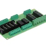
MAKER FACTORY 2134131 4 Channel Relay
Module Instructions
BN 2134131
Version: 2
Safety Instructions
![]() Do not touch connections carrying voltages above 25 V/AC or 35 V/DC.
Do not touch connections carrying voltages above 25 V/AC or 35 V/DC.
- Be especially careful when dealing with voltages higher than 25 V alternating (AC) or 35 V direct voltage (DC)! Even at these voltages, it is possible to receive a fatal electric shock if you touch electrical conductors.
Delivery Content
- Product
Description
Use the product to switch components integrated into your circuits that require high power. The circuits are optoisolated.
The module features 4 high-current rated relays:
- l 250 V/AC / 10 A
- 125 V/AC / 10 A
- 30 V/DC / 10 A
- 28 V/DC / 10 A
Each relay comes with a status indicator light. The board has a power indicator light. The board can be directly controlled through a micro-controller, including
- Arduino®, Raspberry Pi®, 8051, AVR, PIC, DSP, ARM, MSP430, TTL logic
Pinout / Pin Map
| Pin | Description |
| VCC | Power (5/12 V/DC) |
| GND | Ground |
| IN-1 | Signal pin. Arduino® and control circuit 1 |
| IN-2 | Signal pin. Arduino® and control circuit 2. |
| IN-3 | Signal pin. Arduino® and control circuit 3. |
| IN-4 | Signal pin. Arduino® and control circuit 4. |
| COM | Common pin. Usually, directly connects to < GND > unless you intend to change the TTL mode(default: HIGH level). |
| NO | Normally Open Connection |
| NC | Normally Closed Connection |
| C | Middle pin: Common connection. Connects to load. |
Note: There are no NO, NC, and C imprints on the product. Instead, observe the diagrams near the relay terminals.
Example Application
In this example, we will switch on and off two lights.
Each light comes with its own power supply as indicated in the diagram.
The left light connects to Relay 1 and the light on the right to Relay 4. In a real application, you may be switching a fridge, TV, or industrial appliance instead of battery-powered lights.
The instructions use the Arduino® platform to illustrate product use. You can also use an Arduino derivative or another platform that supports this type of product.
Connection
Control circuit:
| Module | VCC | GND | IN1 | IN4 |
| Arduino® | 5V | GND | ~6 | 7 |
Power circuit:

Code
#define RELAY1 6
#define RELAY4 7
void setup( ) {
// Initialise the Arduino data pins for OUTPUT
pinMode (RELAY1, OUTPUT);
pinMode (RELAY4, OUTPUT); }
void loop() {
// Turns ON Relays 1
digitalWrite (RELAY1,LOW);
// Wait 2 seconds
delay (2000);
// Turns Relay Off
digitalWrite (RELAY1, HIGH);
// Turns ON Relays 4
digitalWrite (RELAY4, LOW);
// Wait 2 seconds
delay (2000);
// Turns Relay Off
digitalWrite (RELAY4, HIGH); }
Procedure
- Prepare a sketch with the given code and upload it to your board.
- Connect the module/component to the board as shown in the connection diagram or table.
- The relays are switched according to the settings in your code.
Specifications
| Platform/Microcontroller support |
Arduino®, Raspberry Pi®, 8051, AVR, PIC,DSP, ARM, ARM, MSP430, TTL logic |
| Switching Voltage/Current | 250 V/AC / 10 A 125 V/AC / 10 A 30 V/DC / 10 A 28 V/DC / 10 A |
| Control circuit voltage | 12 V/DC or 5 V/DC |
| Control current (Relay 1 – 4) | 15 – 20 mA |
| Isolation | Opto-isolated |
| Dimensions (approx.) | 77 x 55 x 20 mm |
| Weight (approx.) | 60 g |
Disposal
![]() Electronic devices are recyclable waste and must not be disposed of in the household waste. At the end of its service life, dispose of the product in accordance with applicable regulatory guidelines. You thus fulfill your statutory obligations and contribute to the protection of the environment.
Electronic devices are recyclable waste and must not be disposed of in the household waste. At the end of its service life, dispose of the product in accordance with applicable regulatory guidelines. You thus fulfill your statutory obligations and contribute to the protection of the environment.
Legal Notice
This is a publication by Conrad Electronic SE, Klaus-Conrad-Str. 1, D92240 Hirschau ( www.conrad.com ).
All rights including translation reserved. Reproduction by any method, e.g. photocopy, microfilming, or the capture in electronic data processing systems requires prior written approval by the editor. Reprinting, also in part, is prohibited.
 This publication represents the technical status at the time of printing. Copyright 2022 by Conrad Electronic SE.
Documents / Resources
 |
MAKER FACTORY 2134131 4 Channel Relay Module [pdf] Instructions 2134131 4 Channel Relay Module, 2134131, 4 Channel Relay Module |