GRAPHTEC GL260 Multi Channel Data Logger
Product Information
Specifications
- Model: GL260
- Quick Start Guide: GL260-UM-801-7L
- Power Source: AC adapter or battery pack (option B-573)
- Input Channels: 10 analog input channels
- Connectivity: USB interface terminal, Wireless LAN (with option B-568)
Product Usage Instructions
Confirmation of the Exterior
Before using the GL260, ensure that there are no cracks, defects, or damages on the unit.
User’s Manual and Software Installation
- Download the USER’S MANUAL (PDF) and software from the manufacturer’s website.
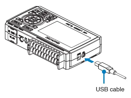
- Connect the GL260 to your PC using the USB cable while the device is powered off.
- Access the GL260’s internal memory on your PC to copy necessary files.
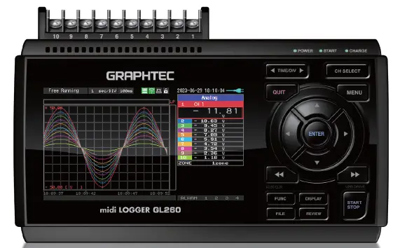
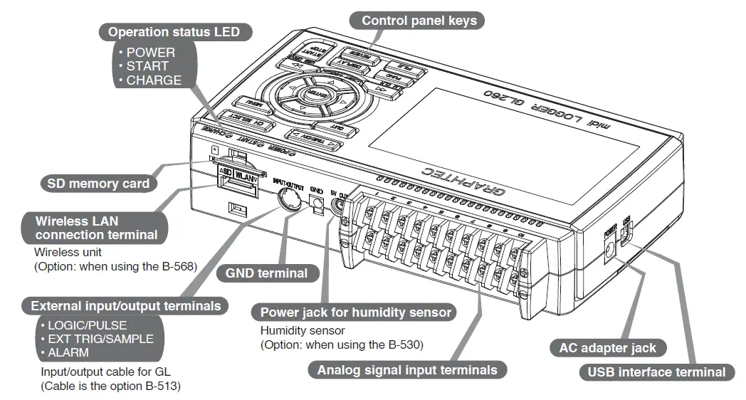
Nomenclature
Top Panel
- Control panel keys
- SD memory card slot
- Wireless LAN connection terminal (with option B-568)
- GND terminal
- External input/output terminals
- Analog signal input terminals
- AC adapter jack
- USB interface terminal
Bottom Panel
- Tilt foot
- Battery cover (option B-573 battery pack compatible)
Connection Procedures
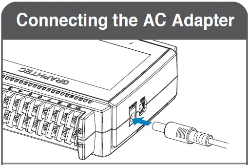
Connecting the AC Adapter
Connect the DC output of the AC adapter to the DC LINE connector on the GL260.
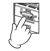
Connecting the Grounding Cable
Use a flathead screwdriver to push the button above the GND terminal while connecting the grounding cable to the GL260. Connect the other end of the cable to ground.
Connecting to Analog Input Terminals
Follow the channel assignments for voltage input, DC voltage input, current input, and thermocouple input. Use shunt resister for current signal conversion to voltage.
Connecting the External Input/Output Terminals
Refer to the signal assignments for logic/pulse input and alarm output. Use designated cables such as B-513 for pulse/logic inputs.
Frequently Asked Questions (FAQ)
- Q: How do I access the GL260’s internal memory on my PC?
- A: Connect the GL260 to your PC using a USB cable while the device is powered off. The internal memory will be recognized by your PC for file access.
- Q: Can I use a battery pack with the GL260?
- A: Yes, you can install a battery pack (option B-573) on the bottom panel of the GL260 for portable power.
Quick Start Guide
First
Thank you for choosing Graphtec midi LOGGER GL260.
The Quick Start Guide is to assist with the basic operations.
Please refer to the USER’S MANUAL (PDF) for more in-depth information.
Confirmation of the exterior
Check the exterior of the unit to ensure that there are no cracks, defects, or any other damages before use.
Accessories
- Quick Start Guide: 1
- Ferrite core: 1
- AC cable/AC adapter: 1
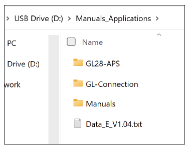
Files stored in the internal memory
- GL260 User’s Manual
- GL28-APS (Windows OS software)
- GL-Connection (Waveform viewer and Control software)*
When the internal memory is initialized, the included files are deleted. If you have deleted the User’s Manual and the supplied software from the internal memory, please download them from our website.
Registered trademarks
- Microsoft and Windows are registered trademarks or brands of the US Microsoft Corporation in the USA and other countries..
- NET Framework is a registered trademark or trademark of US Microsoft Corporation in the USA and other countries.
About the User’s Manual and Included Software
The user’s manual and accompanying software are stored in the internal memory of the instrument.
Please copy it from the internal memory to your computer. To copy, see the next section. When you initialize the internal memory, the bundled files are also deleted.
Deleting the included files will not affect the operation of the instrument, but we recommend that you copy the files to your computer beforehand.If you have deleted the user’s manual and attached software from the internal memory, please download them from our website.
GRAPHTEC Website: http://www.graphteccorp.com/
To copy bundled files in USB DRIVE mode
- Connect the AC adapter cable with the power off, and then connect the PC and the GL260 with the USB cable.
- While holding down the START/STOP button, turn on the GL260’s power switch.
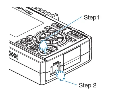
- The GL260’s internal memory is recognized by the PC and can be accessed
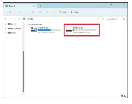
- Copy the following folders and files to your
Nomenclature

Connection Procedures
- Connect the DC output of the AC adapter to the connector indicated as “DC LINE” on the GL260.
- Use a flathead screwdriver to push the button above the GND terminal while connecting the grounding cable to the GL260.
Connect the other end of the cable to ground.

Connect to the Analog Input Terminals

CAUTION: Connect wire to the designated channel, where individual channels are numbered.
Connect the External Input/Output Terminals
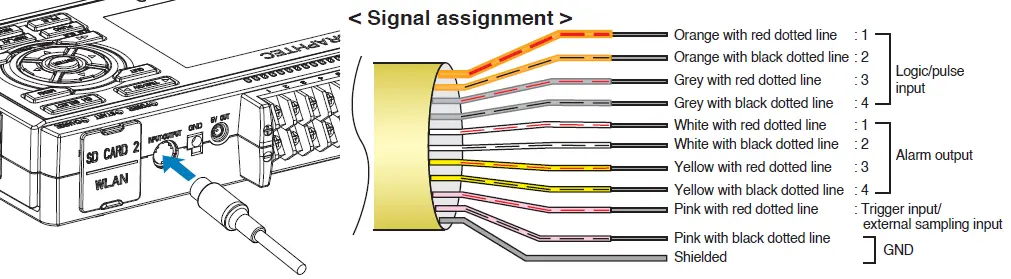
(For logic/pulse input, alarm output, trigger input, external sampling pulse input) * Requires B-513 pulse/logic cable.
Internal memory
The internal memory is not removable.
Mounting SD Card

< How to remove >
The SD memory card is released by pushing gently on the card. Then, pull to remove the card.
CAUTION: To remove a SD memory card, push in gently to release the card before pulling. When the optional wireless LAN unit is installed, the SD memory card cannot be mounted. The POWER LED blinks while accessing the SD memory card.
Connect with PC
- To connect a PC using a USB cable, attach the supplied ferrite core to the USB cable as shown.

- To connect GL260 and PC, use a cable with A-type and B- type connectors.

GL260 midi LOGGER complies with the EMC Directive when the supplied ferrite core is attached to a USB cable.
Safety Guide for using GL260
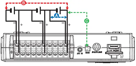
Maximum input voltage
If a voltage exceeding the specified value goes into the instrument, the electrical relay in the input will be damaged. Never input a voltage exceeding the specified value at any moment.
< Between +/– terminals(A) >
Maximum input voltage: 60Vp-p (Range of 20mV to 1V) 110Vp-p (Range of 2V to 100V)
< Between Channel to channel (B) >
- Maximum input voltage: 60Vp-p
- Withstand voltage: 350 Vp-p at 1 minute
< Between Channel to GND (C) >
- Maximum input voltage: 60Vp-p
- Withstand voltage: 350 Vp-p at 1 minute
Warm-up
GL260 requires approximately 30 minutes warm-up time to deliver the optimum performance.
Unused channels
The analog input section can frequently have cases of impedance.
Left open, measured value may fluctuate due to noise.
To rectify, set unused channels to “Off” in the AMP setting menu or short the + and – terminals for better result.
Noise countermeasures
If measured values fluctuate due to extraneous noise, run the following countermeasures. (Results may vary according to noise type.)
- Ex 1 : Connect the GL260’s GND input to ground.
- Ex 2 : Connect GL260’s GND input to measurement object’s GND.
- Ex 3 : Operate GL260 with batteries (Option: B-573).
- Ex 4 : In the AMP settings menu, set filter to any setting other than “Off”.
- Ex 5 : Set the sampling interval which enables GL260’s digital filter (see table below).
| Number of Measuring Channels *1 | Allowed Sampling Interval | Sampling Interval which enables Digital Filter |
| 1 Channel or less | 10 msec or slower *2 | 50 msec or slower |
| 2 Channel or less | 20 msec or slower *2 | 125 msec or slower |
| 5 Channel or less | 50 msec or slower *2 | 250 msec or slower |
| 10 Channel or less | 100 msec or slower | 500 msec or slower |
- Number of Measuring Channels is the number of active channels in which input settings are NOT set to “Off”.
- Temperature cannot be set when the active sampling interval is set to 10 ms, 20 ms or 50 ms.
Descriptions of the Control Panel Keys
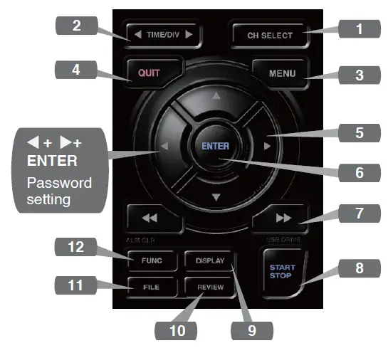
- CH SELECT
Switches between analog, logic pulse, and calculation display channels. - TIME/DIV
Push the [TIME/DIV] key to change the time axis display range on the waveform screen. - MENU
Push the [MENU] key to open a setup menu. As you push the [MENU] key the setup screen tabs change in the sequence shown below.
- QUIT (LOCAL)
Push the [QUIT] key to cancel the settings and return to the default status.
If GL260 is in a Remote (Key Lock) status and is run by a computer via a USB or WLAN interface, push the key to return to a normal operating status. (Local).  Keys (DIRECTION KEYS)
Direction keys are used to select menu setup items, to move the cursors during a data replay operation.- ENTER
Push the [ENTER] key to submit the setting and to confirm your settings.  Keys (KEY LOCK)
Fast forward and rewind keys are used to move the cursor at high speed during replay or change the operation mode in the file box. Hold down both keys simultaneously for at least two seconds to lock the key buttons. (Orange key at the top right of window indicates locked status).
To cancel key lock status, push both key again for at least two seconds.
* Pushing these keys simultaneously with the key enables password protection for the key lock operation.
- START/STOP (USB DRIVE MODE)
Push the [START/STOP] key to initiate start and stop of a recording when GL260 is in the Free Running mode.
If the key is pushed while turning the power to the GL260 on, the unit will switch from the USB connection to USB DRIVE mode.
For more information about the Drive Mode of the USB, refer to the User’s Manual. - DISPLAY
Push the [DISPLAY] key.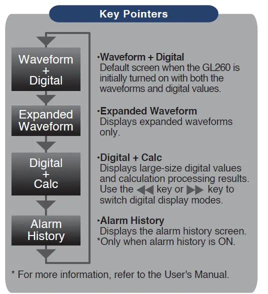
- REVIEW
Push the [REVIEW] key to replay recorded data.
If the GL260 is in the Free Running mode, data files that have already been recorded will be displayed.
If the GL260 is still recording data, the data is replayed in a 2-screen format.
Press the [REVIEW] button to switch between the recorded data and real time data.
A data replay operation will not be performed if data has not been recorded. - FILE
This is used to operate the internal memory and SD memory card, or for file operation, screen copy and save/load current settings. - FUNC
Functional operations allow you to perform frequently used functions every time.

- Status message display area : Displays the operating status.
- Time/DIV display area : Displays the current time scale.
- Sampling interval display : Displays the current sampling interval
- Device access display : Displayed in red when accessing the internal memory.
(Internal memory) - Device access display (SD memory card / wireless LAN display) : Displayed in red when accessing the SD memory card. When the SD memory card is inserted, it is displayed in green.
(In station mode, the signal strength of the connected base unit is displayed. Also, in access point mode, the number of connected handsets is displayed. It turns orange when the wireless unit is operating.) - Remote lamp : Displays the remote status. (Orange = Remote status, white = Local status)
- Key lock lamp : Displays the key lock status. (Orange = keys locked, white = not locked)
- Clock display : Displays the current date and time.
- AC/Battery status indicator : Displays the following icons to indicate the operating status of the AC power and the battery.
Note: Use this indicator as a guideline because remaining battery power is an estimate. This indicator does not guarantee the operating time with battery.
- CH select : Displays analog, logic, pulse, and calculation.
- Digital display area : Displays the input values for each channel. The and keys can be used to select the active channel (enlarged display). The selected active channel is displayed at the very top of the waveform display.
- Quick settings : Displays items that can be easily set. The
 keys can be used to activate a Quick settings item, and the
 keys to change the values.
 - Alarm display area : Displays the status of the alarm output. (Red = alarm generated, white = alarm not generated)
- Pen display : Displays the signal positions, trigger positions, and alarm ranges for each channel.
- File name display area: Displays the recorded file name during the recording operation. When data is being replayed, the display position and cursor information are displayed here.

- Scale lower limit : Displays the lower limit of the scale of the currently active channel.
- Waveform display area : The input signal waveforms are displayed here.
- Scale upper limit : Displays the upper limit of the scale of the currently active channel.
- Recording bar : Indicates the remaining capacity of the recording medium during data record.
When data is being replayed, the display position and cursor information are displayed here.

Included Software
The GL260 comes with two Windows OS-specific software applications.
Please use them as appropriate.
- For simple control, use “GL28-APS”.
- For control of multiple models, use GL-Connection.
The latest version of the included software and USB driver can also be downloaded from our website.
GRAPHTEC Website: http://www.graphteccorp.com/
Install USB Driver
To connect the GL260 to the computer via USB, a USB driver must be installed on the computer. The “USB Driver” and “USB Driver Installation Manual” are stored in the built-in memory of the GL260, so please install them according to the manual. (Location of the manual: “Installation_manual” folder in “USB Driver” folder)
GL28-APS
The GL260, GL840, and GL240 can be connected via USB or LAN to control and operate settings, recording, data playback, etc. Up to 10 devices can be connected.
| Item | Required environment |
| OS | Windows 11 (64Bit)
Windows 10 (32Bit/64Bit) * We do not support OSs for which support by the OS manufacturer has ended. |
| CPU | Intel Core2 Duo or higher recommended |
| Memory | 4GB or more recommended |
| HDD | 32GB or more free space recommended |
| Display | Resolution 1024 x 768 or higher,65535 colors or more (16Bit or more) |
GL-Connection
Various models such as GL260, GL840, GL240 can be controlled and operated via USB or LAN connection for setting, recording, data playback, etc.
Up to 20 devices can be connected.
| Item | Required environment |
| OS | Windows 11 (64Bit)
Windows 10 (32Bit/64Bit) * We do not support OSs for which support by the OS manufacturer has ended. |
| CPU | Intel Core2 Duo or higher recommended |
| Memory | 4GB or more recommended |
| HDD | 32GB or more free space recommended |
| Display | Resolution 800 x 600 or higher,65535 colors or more (16Bit or more) |
Installation Instructions
- Download the latest installer from our website.
- Unzip the compressed file and double-click “setup.exe” in the folder to start the installer.
- From this point on, follow the instructions of the installation program to continue.
Specifications are subject to change without notice.
GL260 Quick Start Guide (GL260-UM-801-7L)
April 24, 2024 1st editon-01
Documents / Resources
 |
GRAPHTEC GL260 Multi Channel Data Logger [pdf] User Guide GL260, GL260 Multi Channel Data Logger, GL260, Multi Channel Data Logger, Channel Data Logger, Data Logger, Logger |