ScanLog Multi-Channel Data-Logger

Product Information: ScanLog (PC) 4 / 8 / 16 Channel Recorder + PC Interface
- Jan 2022
- Operation Manual
- Designed for quick reference to wiring connections and parameter searching
- For more details on operation and application, visit www.ppiindia.net
- Located at 101, Diamond Industrial Estate, Navghar, Vasai Road (E), Dist. Palghar – 401 210
- Sales: 8208199048 / 8208141446
- Support: 07498799226 / 08767395333
- Email: sales@ppiindia.net, support@ppiindia.net
Product Usage Instructions:
To use the ScanLog (PC) 4 / 8 / 16 Channel Recorder + PC Interface, follow the steps below:
Operator Parameters:
Set batch start, balance slot time batch stop, and read-only settings. Choose whether or not to enable batch start and batch stop.
Alarm Settings
Select the channel and alarm type. Choose between “None,” “Process Low,” or “Process High” for AL1 type. Set the AL1 setpoint and hysteresis. Choose whether or not to enable AL1 inhibit. The actual available options depend on the numbers of alarms set per channel on the Alarm configuration page.
Device Configuration:
Choose whether or not to delete records. Set the recorder ID from 1 to 127.
Channel Configuration:
Choose whether or not to use all Chan Common settings. Select the channel and input type. Refer to Table 1 for input type settings. Set the signal low, signal high, range low, range high, low clipping, low clip value, high clipping, high clip value, and zero offset.
Alarm Configuration:
Set the number of alarms per channel from 1 to 4.
Recorder Configuration:
Set the normal interval from 0:00:00 (H:MM:SS) to 2:30:00 (H:MM:SS). Choose whether or not to enable zoom interval, alarm toggle, and recording mode. Choose between “Continuous” or “Batch” mode. Set the batch time, and choose whether or not to enable batch start and batch stop.
RTC Setting:
Set the time (HH:MM), date, month, year, and unique ID number (ignore).
Utilities:
Choose whether or not to lock or unlock the device.
ScanLog (PC)
4 / 8 / 16 Channel Recorder + PC Interface
This brief manual is primarily meant for quick reference to wiring connections and parameter searching. For more details on operation and application; please log on to www.ppiindia.net
| OPERATOR PARAMETERS | |
| Parameters | Settings |
| Batch Start | No Yes |
| Balance Slot Time | Read Only |
| Batch Stop | No Yes |
| ALARM SETTINGS | |
| Parameters | Settings (Default Value) |
| Select Channel | PC Version
For 4C : Channel-1 to Channel-4 For 8C : Channel-1 to Channel-8 For 16C : Channel-1 to Channel-16 |
| Select Alarm | AL1, AL2, AL3, AL4
(The actual available options depends on the numbers of Alarms set per channel on Alarm configuration page) |
| AL1 Type | None Process Low Process High (Default : None) |
| AL1 Setpoint | Min. to Max. of selected input type range (Default : 0) |
| AL1 Hysteresis | 1 to 30000 (Default : 20) |
| AL1 Inhibit | No Yes (Default : No) |
| DEVICE CONFIGURATION | |
| Parameters | Settings (Default Value) |
| Delete Records | No Yes
(Default : No) |
| Recorder ID | 1 to 127
(Default : 1) |
| CHANNEL CONFIGURATION | |
| Parameters | Settings (Default Value) |
| All Chan Common | No Yes (Default : No) |
| Select Channel | PC Version
For 4C : Channel-1 to Channel-4 For 8C : Channel-1 to Channel-8 For 16C : Channel-1 to Channel-16 |
Parameters: Settings (Default Value)
Input Type: Refer Table 1 (Default : 0 to 10 V)
Resolution: Refer Table 1
Signal Low
| Input Type | Settings | Default |
| 0 to 20mA | 0.00 to Signal High | 0.00 |
| 4 to 20mA | 4.00 to Signal High | 4.00 |
| 0 to 80mV | 0.00 to Signal High | 0.00 |
| 0 to 1.25V | 0.000 to Signal High | 0.000 |
| 0 to 5V | 0.000 to Signal High | 0.000 |
| 0 to 10V | 0.00 to Signal High | 0.00 |
| 1 to 5V | 1.000 to Signal High | 1.000 |
Signal High
| Input Type | Settings | Default |
| 0 to 20mA | Signal Low to 20.00 | 20.00 |
| 4 to 20mA | Signal Low to 20.00 | 20.00 |
| 0 to 80mV | Signal Low to 80.00 | 80.00 |
| 0 to 1.25V | Signal Low to 1.250 | 1.250 |
| 0 to 5V | Signal Low to 5.000 | 5.000 |
| 0 to 10V | Signal Low to 10.00 | 10.00 |
| 1 to 5V | Signal Low to 5.000 | 5.000 |
Range Low: -30000 to +30000 (Default : 0)
Range High: -30000 to +30000 (Default : 1000)
Low Clipping: Disable Enable (Default : Disable)
Low Clip Val: -30000 to High Clip Val (Default : 0)
High Clipping: Disable Enable (Default : Disable)
High Clip Val: Low Clip Val to 30000 (Default : 1000)
Zero Offset: -30000 to +30000 (Default : 0)
| ALARM CONFIGURATION | |
| Parameters | Settings (Default Value) |
| Alarms/Chan | 1 to 4
(Default : 4) |
| RECORDER CONFIGURATION | |
| Parameters | Settings (Default Value) |
| Normal Interval | 0:00:00 (H:MM:SS) to 2:30:00 (H:MM:SS) (Default : 0:00:30) |
| Zoom Interval | 0:00:00 (H:MM:SS) to 2:30:00 (H:MM:SS) (Default : 0:00:10) |
| Alarm Toggl Rec | Disable Enable (Default : Enable) |
| Recording Mode | Continuous Batch (Default : Continuous) |
| Batch Time | 0:01 (HH:MM) to 250:00 (HHH:MM) (Default : 1:00) |
| Batch Start Batch Stop | No Yes |
| RTC SETTING | |
| Parameters | Settings |
| Time (HH:MM) | 0.0 to 23:59 |
| Date | 1 to 31 |
| Month | 1 to 12 |
| Year | 2000 to 2099 |
| Unique ID Number (Ignore) |
|
| UTILITIES | |
| Parameters | Settings (Default Value) |
| Lock Unlock | No Yes (Default : No) |
| Factory Default | No Yes (Default : No) |
| TABLE 1 | ||
| Option | Range (Min. to Max.) | Resolution & Unit |
| Type J (Fe-K) | 0.0 to +960.0°C |
1 °C or 0.1 °C |
| Type K (Cr-Al) | -200.0 to +1376.0°C | |
| Type T (Cu-Con) | -200.0 to +387.0°C | |
| Type R (Rh-13%) | 0.0 to +1771.0°C | |
| Type S (Rh-10%) | 0.0 to +1768.0°C | |
| Type B | 0.0 to +1826.0°C | |
| Type N | 0.0 to +1314.0°C | |
| Reserved for customer specific Thermocouple type not listed above. The type shall be specified in accordance with the ordered (optional on request) Thermocouple type. | ||
| RTD Pt100 | -199.9 to +600.0°C | 1°C or 0.1 °C |
| 0 to 20 mA |
-30000 to 30000 units |
1 0.1 0.01 0.001 units |
| 4 to 20 mA | ||
| 0 to 80 mV | ||
| Reserved | ||
| 0 to 1.25 V |
-30000 to 30000 units |
|
| 0 to 5 V | ||
| 0 to 10 V | ||
| 1 to 5 V | ||
| FRONT PANEL KEYS | ||
| Symbol | Key | Function |
 |
Scroll | Press to scroll through various Process Information Screens in Normal Operation Mode. |
 |
Alarm Acknowledge | Press to acknowledge / mute alarm output (if active) & to view Alarm Status screen. |
 |
DOWN |
Press to decrease the parameter value. Pressing once decreases the value by one count; keeping pressed speeds up the change. |
 |
UP |
Press to increase the parameter value. Pressing once increases the value by one count; keeping pressed speeds up the change. |
 |
SET-UP | Press to enter or exit set-up mode. |
 |
ENTER | In Run Mode, press to toggle between Auto & Manual Scan Mode. (Only for 16 Channel version)
In Set-up Mode, press to store the set parameter value and to scroll to the next parameter. |
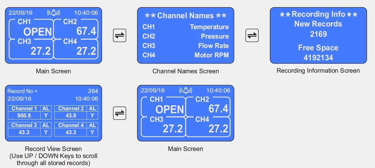
SCROLLING THROUGH VARIOUS SCREENS
The screen shown below are for 4 Channel Version. The sequence is the same for 8 & 16 Channel Version.
VIEWING ALARM STATUS SCREEN 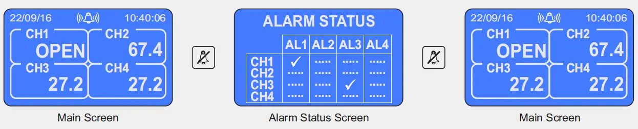
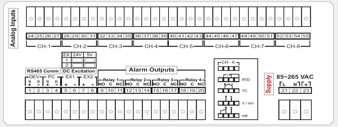
16 Channel With Alarm Relay Outputs 
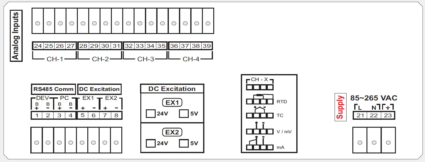
ELECTRICAL CONNECTIONS
4 Channel Without Alarm Relay Outputs
4 Channel With Alarm Relay Outputs 
8 Channel Without Alarm Relay Outputs 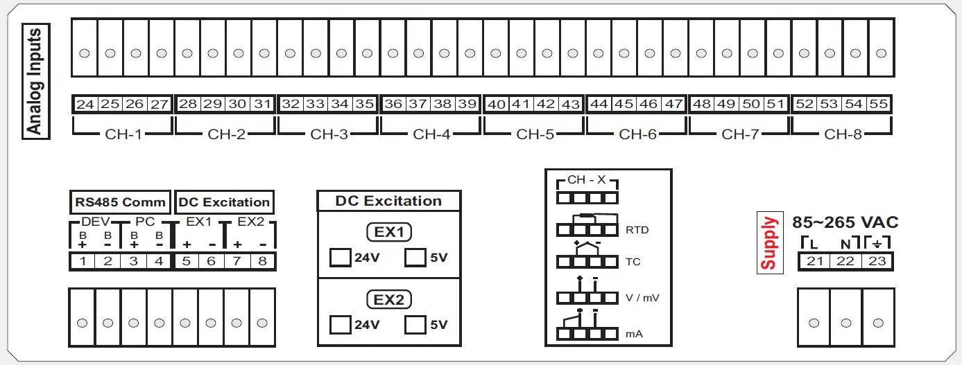
8 Channel With Alarm Relay Outputs
Documents / Resources
 |
PPI ScanLog Multi-Channel Data-Logger [pdf] Instruction Manual ScanLog Multi-Channel Data-Logger, Multi-Channel Data-Logger, Channel Data-Logger, Data-Logger, Logger |


