![]()
 WLED Series LED Strip Controller
User Instruction
GL-C-014WL, GL-C-015WL
GL-C-015WL-M, GL-C-015WL-D
ESP8266 WLED Digital LED Controller
Model: GL-C-014WL
Output Current/Channel: 10A Max
Temperature: -20~45°C
Dimensions: 108x45x18mm
Input Voltage: DC 5-24V
Total Output Current: 15A Max
Wireless Communication: WiFi Wiring Terminal Instructions
The WLED controller can support a total of three output channels. The output terminal connections “G D V” correspond to the “GND DATA VCC” pins of the digital LED strips. Among them, D refers to the default output group for GPIO2, so please prioritize using this group. The other group, D for GPIO1, can only be used after configuration in the APP. I014 is an extended GPIO signal port that can be customized for use.
ESP32 WLED Digital LED Controller
Model: GL-C-015WL
Output Current/Channel: 10A Max
Temperature: -20~45°C
Dimensions: 108x45x18mm
Input Voltage: DC 5-24V
Total Output Current: 15A Max
Wireless Communication: WiFi Wiring Terminal Instructions
The WLED controller can support a total of three output channels. The output terminal connections “G D V” correspond to the “GND DATA VCC” pins of the digital LED strips. Among them, D refers to the default output group for GPIO16, so please prioritize using this group. The other group, D for GPIO2, can only be used after configuration in the APP. I033 is an extended GPIO signal port that can be customized for use.
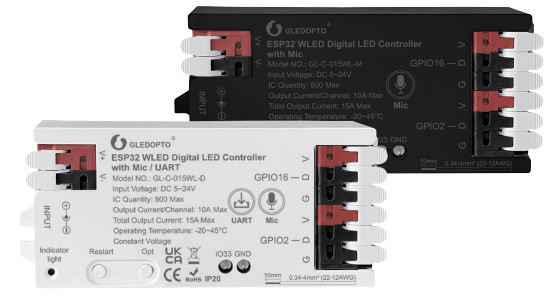
ESP32 WLED Digital LED Controller with Mic
Model: GL-C-015WL-M/GL-C-015WL-D
Output Current/Channel: 10A Max
Temperature: -20-45°C
Dimensions: 108x45x18mm
Input Voltage: DC 5-24V
Total Output Current: 15A Max
Wireless Communication: WiFi
 Wiring Terminal Instructions
The WLED controller can support a total of three output channels. The output terminal connections “G D V” correspond to the “GND DATA VCC” pins of the digital LED strips. Among them, D refers to the default output group for GPIO16, so please prioritize using this group. The other group, D for GPIO2, can only be used after configuration in the APP. 1033 is an extended GPIO signal port that can be customized for use.
APP Download Method
- IOS: “App Store” Search and download WLED or WLED Native within the app.

- Android: Download from the website https://github.com/Aircoooke/WLED-App/releases.

APP Configuration Steps
- Power on the WLED controller.
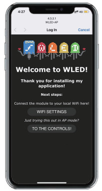
- Open the phone settings and enter WiFi settings, find”WLED-AP” and connect to it with the password “wled1234”.

- After successful connection, it will automatically jump to the WLED page (or enter the website 4.3.2.1 in the browser to enter the WLED page).
- Click “WIFI SETTINGS”, set the WiFi account and password, and the click”Save & Connect” at the top of the screen to save.

- Keep the phone and WLED controller connected to the same WIFI connection, enter the WLED APP (See figure 5-1), click the “+” in the upper right corner of the screen (See figure 5-2), and then click “DISCOVER LIGHTS…” (See figure 5-3). When the button below displays “Found WLED!”, it means that the WLED controller has been found (See figure 5-4). Click the checkmark in the upper right corner to return to the main page. The found WLED controller will be displayed in the list (See figure 5-5).

LED Strip Configuration
Go to the WLED control page and click on the “Config” button in the upper right corner. Then, select “LED Preferences” and navigate to “Hardware setup” to configure the LED strip information.
Relay Configuration
Relay Configuration Go to the WLED control page, click on the top right corner “Config”, select “LED Preferences”, then find “Relay GPIO”. Configure Relay GPIO as 12, uncheck Invert, and click Save to apply the settings.
 Note: When using this function, every time the light is turned on or off, the power to the output terminal will be simultaneously turned on or off to save electricity. It is important to note that this function cannot turn off the power supply for backup power.
Mic Configuration (If this feature is available)
- Go to the WLED control page, click on “Config” in the top right corner, select “Usermods”, find “Digitalmic” after entering, configure according to the configuration information, click “Save” after configuration is complete, and then power off the controller.
- Go to the WLED control page, click on “Info” at the top, click on the button next to “AudioReactive” to use the Mic.
Configuration Information:
- Microphone type: Generic 125
- 125 SD pin: 26
- 125 WS pin: 5
- 125 SCK pin: 21
 Note: After configuring the microphone parameters, you need to power off and on the controller once to use the microphone function.
Restart:
Pressing the button will power off the controller module, releasing it will power it back on. Useful when the controller needs to be restarted after configuring the microphone.
OPT button:
- Short press: Power on/off
- Long press for 1 second: Switch colors.
- Long press for 10 seconds: Reset the WLED controller and activate the WLED-AP hotspot
Reset to Factory Settings
- Button Reset
Long press OPT button for 10 seconds. - APP Reset
Go to the WLED control page and click on the top right corner “Config”. Click on “Security & Updates” at the bottom, and then scroll down to find “Factory reset and check the box.
Click “Save” to reset the controller.
UART Download (if this function is available)
- Open the controller case.
- Remove the jumper cap (used to connect the motherboard power).
- Insert the Micro-B data cable to download.
- After downloading, reinstall jumper cap.
 Jumper cap 1: Connect the PCB bottom board power.
Note: When using Micro-B port for programming, the jumper cap needs to be removed. After downloading, reinstall jumper cap.
Supported Chips
WS2811、WS2811F、WS2812B、WS2814A、SK6812、 SM16703、SM16703SP3、FL19038、FW1935、FL19038, etc.
Troubleshooting and Solution Attention
| Number | Symptoms | Solution |
| 1 | Indicator light is not on | Check whether the input power connection is correct |
| 2 | APP shows “offline” | 1.Check if the phone is on the same network as the controller. 2.Check if the controller is out of the range of the WIFI connection, causing unstable connection. 3.Turn off and on the controller to retry. |
| 3 | APP is connected, but the light strip is not controllable | 1.Check if the power supply is working properly. 2.Check if the power supply voltage matches the light strip. 3.Check if the input power connection is correct. 4• Check if the light strip connection is correct. 5.Check if the GPIO settings in the APP are correct. 6.Check if the light strip IC model in the APP is set correctly. |
| 4 | The brightness of the light strip is low, and the front and back colors are significantly different | 1.Check if the power supply is working properly. 2.Check if the power supply matches the light strip. 3.Check if all connections are good, and use conductive and short wires as much as possible for connection. 4.Add power supply at an appropriate position. 5.Check if the APP has set a limit on brightness or current. |
![]() Attention
Attention
- Before turning on the power, please ensure that all connections are correct and secure, and do not operate while the power is on.
- The product should be used under the rated voltage. Using it under excessive or insufficient voltage may cause damage.
- Do not disassemble the product, as it may cause fire and electric shock.
- Do not use the product in environments exposed to direct sunlight, moisture, high temperatures, etc.
- Do not use the product in metal shielded areas or around strong magnetic fields, as this may severely affect the wireless signal transmission of the product.
Disclaimers
- Our company will update the content of this manual based on the improvement of product functionality. The updates will be displayed in the latest version of this manual, without further notice.
- Due to our continuous adoption of new technologies, product specifications may change without further notice.
- This manual is provided for reference and guidance only and does not guarantee complete consistency with the actual product. The actual application should be based on the actual product.
- The components and accessories described in this manual do not represent the standard configuration of the product. The specific configuration is subject to the packaging.
- All text, tables, and images in this manual are protected by relevant national laws and may not be used without our permission.
- This product may be compatible with third-party products (such as apps, hubs, etc.), but our company does not take responsibility for compatibility issues or partial loss of functionality caused by changes in third-party products.
GL-C-1-015WLv1.0
This device complies with part 15 of the FCC Rules. Operation is subject to the following two conditions: (1) This device may not cause harmful interference, and (2) this device must accept any interference received, including interference that may cause undesired operation.
Any Changes or modifications not expressly approved by the party responsible for compliance could void the user’s authority to operate the equipment.
Note: This equipment has been tested and found to comply with the limits for a Class B digital device, pursuant to part 15 of the FCC Rules. These limits are designed to provide reasonable protection against harmful interference in a residential installation. This equipment generates uses and can radiate radio frequency energy and, if not installed and used in accordance with the instructions, may cause harmful interference to radio communications. However, there is no guarantee that interference will not occur in a particular installation. If this equipment does cause harmful interference to radio or television reception, which can be determined by turning the equipment off and on, the user is encouraged to try to correct the interference by one or more of the following measures:
– Reorient or relocate the receiving antenna.
– Increase the separation between the equipment and receiver.
– Connect the equipment into an outlet on a circuit different from that to which the receiver is connected.
– Consult the dealer or an experienced radio/TV technician for help.
– This equipment complies with FCC radiation exposure limits set forth for an uncontrolled environment.
This equipment should be installed and operated with minimum distance 20cm between the radiator & your body.
![]()
![]()
LED-Trading Tobias Ebert
Schoeneicher Str. 42, Schoeneiche b.
Berlin, Germany, 15566
0049 30 641 689 17
info@led-trading.de
Documents / Resources
 |
GLEDOPTO GL-C-01 Series LED Strip Controller [pdf] Instruction Manual GLC015WLD, 2BL9K-GLC015WLD, 2BL9KGLC015WLD, GL-C-01 Series LED Strip Controller, GL-C-01 Series, LED Strip Controller, Strip Controller, Controller |