![]() INSTALLING THE THREE MAIN
INSTALLING THE THREE MAIN
TYPES OF LOAD MANAGEMENT
VERSION 1 
Load Management – Version 1
Load management is a critical aspect of installing EV charge points. It involves the effective control and optimisation of electrical loads to ensure the safe and efficient operation of systems of the equipment. Three main types of load management are “Managing Operator Current,” “Static Load Control,” and “Dynamic Load Control.” Let’s delve into the step by step instructions for each load management.
Before accessing any of the three main types of load management, the FIRST step is accessing the MASTER and SLAVE controller using Step 1 and Step 2 below.
Step 1
You will need: A Laptop and a micro-USB to USB cable. This should be plugged in from your laptop to your charge controller. If the charger has two charge controllers make sure you plug into the charge controller on the right-hand side and DO NOT remove any cables or links bet ween the charge controllers.
When you have t ha t done you need t o open a web browser and type in your IP address (192.168.123.123/operator) to access the charge controller
Click on ”Master”, which is the left-hand side charge controller. Then on ”Operator”.
It will ask for username and password:
| Username | operator |
| Password | yellow_zone OR cherry_zone |
Step 2
OPEN ANOTHER TAB ON YOUR BROWSER
Click on ”Slave”, which is the right-hand side charge controller. Then on ”Operator”.
It will ask for username and password:
| Username | operator |
| Password | yellow_zone OR cherry_zone |
For a more in-depth description of logging in, please go to our “Logging into controller” user-guide.
Managing Operator Current
Managing operator current refers to the process of overseeing and regulating the flow of electrical current. This is essential for ensuring that the current remains within safe and desirable limits. The goal is to prevent electrical overloads, short circuits, and equipment failures.
Step 1
Log into the MASTER and SLAVE controller using Step 1 and Step 2 on page 1.
Step 2
You will now have access to the operating settings. Scroll down to find the Operating Current. You can change the operating current for each of the sides of the charger to whatever your desire or need.
- MAXIMUM 32AMP per phase per outlet.
- MINIMUM 6AMP per phase per outlet.
Step 3
Once you have changed the operating current click on ”save and restart”, located at the bottom left corner of the screen on both open tabs.
Static Load Control (No External Meter)
Static load control focuses on the management of constant or unchanging electrical loads. The objective of static load control is to optimise the distribution of power to ensure the most efficient and stable operation of these loads. By carefully managing static loads, homes and businesses can reduce energy consumption, minimize operational costs of the electric vehicle chare point, and enhance the overall reliability of their system.
Step 1
Log into the MASTER and SLAVE controller using Step 1 and Step 2 on page 1.
Step 2
You will then have access to the operating settings. If you scroll down to find the option “Dynamic Load Management”. It will say “Disabled”, click on the drop-down menu and select the appropriate options for the application.

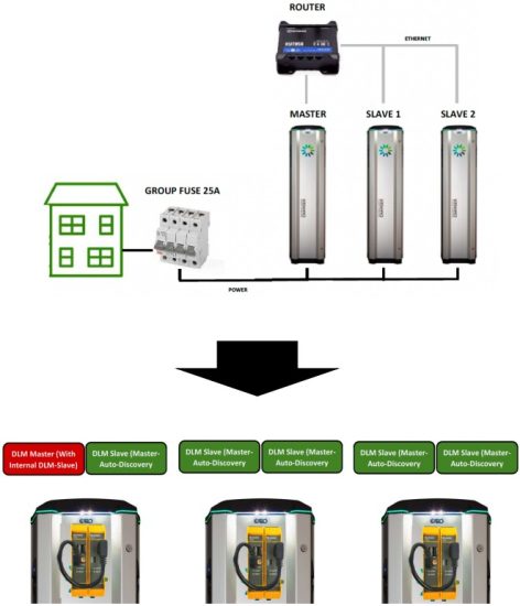
DLM Master (with internal DLM-Slave) – This option is for when you have more than one charge point connected on a site. This is only to be selected for the Master side of the charger.
Step 3
Once the option is selected you will see added settings appear underneath.

DLM Network ID – should be changed to a number for the rest of the chargers to find it. We recommend using “1”.
EVSE Sub-Distribution Limit – This is where you set what AMPS are always available to the group of chargers.
Always set the values of “EVSE Sub-Distribution Limit” and “Operator EVSE Sub-Distribution Limit” to the same value during setup.
Step 4
Click on SAVE and RESTART and wait for the Charge Controller to restart. After the reboot a new button will appear along the left-hand side of the web interface “>DLM”. This will navigate to the “DLM Master view”, which will give access to the overlook of the DLM systems status and all its connected slave charge points.

Step 5
CLICK ON THE “OPERATOR” SETTINGS
For the Slave Charge Controller, you will select DLM Slave (Master-Auto-Discovery).

Like the Master Controller more settings will appear underneath, but not as many options. The only setting needed to change here is DLM Network ID, which should be set to the same as the Master, we recommend “1”.

Step 6
Click on SAVE and RESTART and wait for the Charge Controller to restart. After the reboot a new button will appear along the left-hand side of the web interface “>DLM”. This will only show the slave side and if it’s connected to the master.
*If disconnected please check previous steps to make sure all settings are correct. If they are, please test all communication cables installed.
Dynamic Load Control (With External Meter)
Dynamic load control is the management of loads that vary over time. In contrast to static loads, dynamic loads fluctuate in their power consumption. Dynamic load control is designed to adjust power distribution in real-time to accommodate changes in load. This ensures that electrical system remain stable, energy-efficient, and responsive to evolving operational requirements.
Step 1
Log into the MASTER and SLAVE controller using Step 1 and Step 2 on page 1.
Step 2
You will now have access to the operating settings. If you scroll down to find the option “Dynamic Load Management”. It will say “Disabled”, click on the drop-down menu and select the appropriate options for the application.

DLM Master (with internal DLM-Slave) – This option is used when you have more than one charge point connected on a site. This is only to be selected for the Master side of the charger.
Step 3
Once the option is selected you will see added settings appear underneath.

DLM Network ID – should be changed to a number for the rest of the chargers to find it. We recommend using “1”.
External Meter Support – should be set to “ON”, additional parameters will become available now.
EVSE Sub-Distribution Limit – This is where you set what AMPS are always available to the group of chargers regardless of the supply on the building.
PLEASE NOTE: If this is set to 100Amps and the Main distribution Limit is set to 200Amps, and the building uses 50 Amps. There will be 150Amp available to the charge points but because the EVSE Distribution is set to 100Amp it will only avail of 100Amp during any circumstance.
Step 4
Main Distribution Limit – Should be set to the size of the main fuse where the external meter is located.

External Load Headroom – This is used as a “current load buffer zone”. Essentially it lowers the Main Distribution Limit in case of fast influx of current/amps on the system.
Step 5
Meter Configuration (Second) – This is where you should identify what meter is being used externally for the Dynamic Load Management.

Step 6
Click on SAVE and RESTART and wait for the Charge Controller to restart. After the reboot a new button will appear along the left-hand side of the web interface “>DLM”. This will navigate to the “DLM Master view”, which will give access to the overlook of the DLM systems status and all its connected slave charge points.
You can also check if the meter is reading/communicating with the charger correctly.


Any further questions on the three GARO Load Management systems. Please call or email the EV Support teams on the below details.
Programming Address On GNM1D-100-RS485
Step 1
Press and hold bottom right-hand key on the meter until “Pass” come up and the zero on the right-hand side flashes.
Step 2
Password is “0000” so keep pressing the bottom right-hand key for 2 seconds until all zeros have stopped flashing.
Step 3
Press left-hand key until P.10 Address should be at “2” or “100” for cluster of chargers.
Step 4
Press and hold the bottom right-hand key until “1” is flashing.
Step 5
Press left-hand key and change address to ”2” or “100” for cluster.
Step 6
When address is changed to “2” keep pressing the bottom right-hand key until all numbers have stopped flashing.
Step 7
Press left hand key until you have reached P.14 (END) press bottom right-hand key to return to the main menu.
Step 8
RX/TX should be flashing in the lower right-hand corner of the home screen which means the unit is communicating with the meter.
Programming Address On GNM3D-RS485
Step 1
Press and hold bottom right-hand key on the meter until “Pass” come up and the zero on the right-hand side flashes.
Step 2
Password is “0000” so keep pressing the bottom right-hand key for 2 seconds until all zeros have stopped flashing.
Step 3
Press left-hand key until P.14 Address should be at “2” or “100” for cluster of chargers.
Step 4
Press and hold the bottom right-hand key until “1” is flashing.
Step 5
Press left-hand key and change address to ”2” or “100” for cluster.
Step 6
When address is changed to “2” keep pressing the bottom right-hand key until all numbers have stopped flashing.
Step 7
Press left hand key until you have reached P.18 (END) press bottom right-hand key to return to the main menu.
Step 8
RX/TX should be flashing in the lower right-hand corner of the home screen which means the unit is communicating with the meter.

UNITED KINGDOM
PHONE NUMBER: +44 (0) 121 3899 444
EMAIL: TECHNICAL@GARO.CO.UK
IRELAND
PHONE NUMBER: +353 (0) 1 866 5360
EMAIL: EV@GARO.IE
Documents / Resources
 |
GARO GTB Load Management [pdf] Instructions GTB_, GLB_, 613 Controller, GTB Load Management, GTB, Load Management, Management |