GARMIN LC102 Spectra LED Control Module
Specifications
- Product Name: Garmin Spectra LED Control Module
- Model Number: GUID-6A3E1D9B-1E17-4069-BF5C-3C82F2202A9B v2
- Release Date: September 2024
Product Usage Instructions
Mounting the Device
- Select a suitable location based on mounting considerations.
- Use included mounting screws or acquire pan-head screws of appropriate length.
- Mark pilot hole locations on the mounting surface.
- Drill pilot holes using a 2 mm (3/32 in.) drill bit.
- Fasten pan-head screws into the pilot holes.
- Secure the device by tightening the screws snugly without overtightening.
Connection Considerations
Prioritize planning the layout of the device, power wiring, NMEA 2000 network, and LED lighting devices before making any connections. Refer to specific connection sections for detailed information.f
Connecting to Power
WARNING: Ensure wiring from the power source to the positive wire of the power wiring harness passes through a circuit breaker or in-line fuse. Refer to ABYC or local standards for fuse/breaker ratings.
NOTICE: Match power supply voltage to LED control module with LED lighting voltage. Do not mix 12 Vdc and 24 Vdc devices. Use 16 AWG marine-grade, fully-tinned copper wire for connections.
FAQ (Frequently Asked Questions)
- Q: Where can I find the latest owner’s manual for my chartplotter or stereo?
A: You can download the latest owner’s manual from the Garmin website by visiting garmin.com/manuals/ or scanning the provided QR code. - Q: What should I do if I encounter difficulties during the installation process?
A: If you face challenges during installation, visit support.garmin.com for assistance.
Important Safety Information
WARNING
See the Important Safety and Product Information guide in the product box for product warnings and other important information.
Failure to install this device according to these instructions could result in personal injury, damage to the vessel or device, or poor product performance.
CAUTION
To avoid possible personal injury or damage to the device and vessel, disconnect the vessel’s power supply before beginning to install the device.
To avoid possible personal injury, always wear safety goggles, ear protection, and a dust mask when drilling, cutting, or sanding.
NOTICE
When drilling or cutting, always check what is on the opposite side of the surface to avoid damaging the vessel.
You must read all installation instructions before beginning the installation. If you experience difficulty during the installation, go to support.garmin.com.
Tools and Supplies Needed
- 16 AWG (1.3 mm2) wire to connect the wiring harness to power
- Inline fuse apporpriately-rated for the power source and connected LEDs (Connecting to Power, page 4).
- 20 AWG (0.5 mm2) wire to connect the wiring harness to lighting
You can purchase marine LED cable from your Fusion® or Garmin® dealer in 100m (328 ft.) lengths (010-13386-00). - #2 Phillips screwdriver
- Appropriately sized marine-grade connectors for connecting the wiring harnesses to the speaker wire
- Wire cutters
- Drill and 2 mm (3/32 in.) drill bit for mounting the LED control module
Getting Started
The Garmin Spectra LED control module allows you to control connected LED lights using compatible Garmin chartplotters and compatible Fusion stereos connected to the same NMEA 2000® network. You can also control connected LED lights using the ActiveCaptain® app.
The Garmin Spectra LED control module is designed for controlling only LED lighting. You must not use this device to control navigation lights, non-LED lighting, or other devices.
This manual contains instructions for installing and performing the initial configuration for the Garmin Spectra LED control module using a Garmin chartplotter or ActiveCaptain app. For complete instructions on using the Garmin Spectra LED control module with a connected chartplotter or Fusion stereo, see the latest chartplotter or stereo owner’s manual.
Downloading the Latest Chartplotter or Stereo Owner’s Manual
For complete operating and customization instructions for the LED lighting features, download the latest version of the owner’s manual for your chartplotter or stereo from the Garmin website.
- Go to garmin.com/manuals/ or scan this QR code.
- Enter the name of your chartplotter or stereo and select the appropriate model from the results.
- Select Owner’s Manual on the manuals page.

Mounting Considerations
Selecting the correct mounting location is critical to optimize the performance of the Garmin Spectra LED control module. When selecting a mounting location, observe these considerations.
- You should mount the device in an accessible location.
- You should not mount the device near fuel tanks or bilge areas where combustible fumes may accumulate.
- You should mount the device in a location with access to a common ground for other electronics.
- When controlling LED speakers, the controller should be mounted within 5 M (16 ft. 4 in.) of the speakers.
- You must mount the device in a location where it is not submerged.
- You should mount the device on a flat, vertical mounting surface, with the wire harness connectors pointing down.
- You should clear the mounting surface of dirt, debris, wax, or coatings.
- You should select a location away from sources that can interfere with the device’s operation. Sources of interference may include strong electromagnetic fields, such as power cables and electric motors.
Mounting the Device
Before you can mount the device, you must select a location in accordance with the mounting considerations. You must use the included mounting screws or acquire pan-head screws of the appropriate length for the mounting surface.
NOTICE
Do not use the Garmin Spectra LED control module as a template when drilling the mounting holes. Drilling through the mounting holes may damage the device and void the warranty.
Do not apply grease or lubricant to the screws when fastening the device to the mounting surface. Grease or other lubricants can cause damage to the device housing.
You must use pan-head screws to secure the device. Using countersunk screws can damage the device housing.
- With the wiring-harness connectors pointing down, hold the device on a flat, vertical mounting surface and mark the locations for the pilot holes.
- Remove the device from the mounting surface.
- Using a 2 mm (3/32 in.) drill bit, drill the pilot holes.
- Fasten the included pan-head screws into the pilot holes.
- Secure the device to the mounting surface by tightening the screws until they are snug.
NOTICE
Do not overtighten the screws because it may damage the device housing.
Connection Considerations
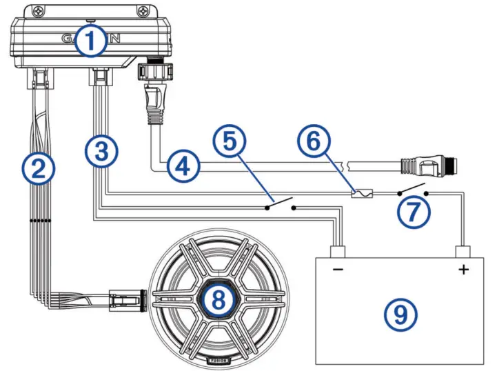
You should carefully plan the layout of the device, the power wiring, the NMEA 2000 network, and all LED lighting devices before making any connections. This is a connection overview. See the relevant connection sections for more information on particular connections.
- Garmin Spectra LED Control Module
- LED wiring harness
- Power wiring harness
- NMEA 2000 cable
- Momentary switch (optional)
- Appropriately rated slow-blow fuse (not included)
- Ignition or ACC switch (recommended)
- 12 or 24 Vdc LED lighting (LED speaker in this example)
- 12 or 24 Vdc power source
When making connections, observe these considerations.
• This device supports a maximum of 2 A per LED wiring harness. When planning lighting connections, consider the power needs of all potential load combinations to ensure that the total active load does not exceed 2 A per LED wiring harness when in use.
• You must connect all lighting to a common ground.
• You must make all bare wire connections using appropriately sized marine-grade, waterproof connectors or waterproof heat-shrink.
• You must insulate any unused bare wire connections after completing installation.
• When extending wires, you must use the appropriate wire gauge for the individual wires on the wiring harnesses.
• To avoid interference, avoid bundling or routing speaker and LED wires together.
This device must connect to the same NMEA 2000 network as the chartplotter or stereo you want to use for controlling the LED lighting (NMEA 2000 Network Connection, page 6).
Connecting to Power
WARNING
The wiring (not included) from the power source to the positive wire of the power wiring harness must run through a circuit breaker or in-line fuse (not included) as close to the power source as possible. See the ABYC or your local and regional standards for the required fuse or breaker rating. Connecting the device to power without a circuit breaker or in-line fuse may cause a fire if there is a short in the cable, resulting in property damage and/or serious personal injury.
NOTICE
The power supply voltage to the LED control module must match the voltage of the LED lighting it is controlling. Mixing 12 Vdc and 24 Vdc devices may damage your LED lighting.
- Route 16 AWG marine-grade, fully-tinned copper wire (not included) to the wiring harness and the common ground location on the boat, and select an option:
- Install a properly rated in-line fuse on the red power wire as close to the power source as possible.
- Identify or install a properly rated circuit breaker, as close to the power source as possible, for use with the power wire.
- Install marine-grade connectors or solder and heat shrink tubing on both the red power and black ground wires.
NOTE: The pink and black wire is for an optional toggle switch, and must not be connected to the ignition (Connecting an Optional Momentary Switch, page 5). - Connect the power plug.
Power Cable Extensions
If necessary, you can extend the power cable using 16 AWG (1.3 mm2) wire, The maximum length of the extension depends on the power source. Use marine-grade connectors or solder and water-resistant heat-shrink tubing when extending the power wires.
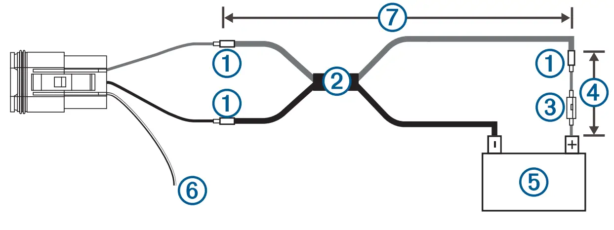
- Splice
- 16 AWG (1.3 mm2) extension wires
- Fuse (not included)
- 20.3 cm (8 in.) minimum cable and fuse length before splice
- 12 or 24 V power source
- The pink and black wire is for an optional toggle switch, and must not be connected to the ignition (Connecting an Optional Momentary Switch, page 5)
- Maximum extension (Maximum Power Cable Extension, page 5)
Maximum Power Cable Extension
To find the maximum extension length you can use, cross-reference the voltage of your power supply with your LED control module. All extensions should be made using 16 AWG (1.3 mm2) marine-grade wire.
| Garmin Spectra Model | 12 Vdc Power Source | 24 Vdc Power Source |
| LC102 | Up to 7.5 m (24 ft. 7 in.) | Up to 15 m (49 ft. 2 in.) |
| LC302 | Up to 2.5 m (8 ft. 2 in.) | Up to 5 m (16 ft. 5 in.) |
Connecting an Optional Momentary Switch
You can connect an optional, normally open momentary switch to the Garmin Spectra LED Control Module to toggle all connected LED lights on and off without using a connected chartplotter, stereo, or app. When toggling lights on, the LEDs will restore the last-used lighting configuration.
- Connect the pink and black wire on the power wiring harness to the same ground connection as the negative wire through a normally open momentary switch (not included).
- If necessary, mount or install the switch according to the instructions provided with the switch.
- Connect the power wiring harness to the LED control module.
Connecting LED Wiring to the Wiring Harnesses
You must use the provided wiring harnesses to connect LED lights to the LED control module. The extension wire needed to connect the LED lights to the wiring harnesses is not included, but you can purchase marine LED cable (010-13386-00) from garmin.com or your Garmin dealer.
WARNING
In order to avoid accidental short circuits, disconnect the power supply to the Garmin Spectra LED control module before making any connections. Failure to disconnect the power supply could result in serious bodily injury, and/or damage to the device and/or vessel.
- Route appropriately gauged marine-grade, fully-tinned copper wire (not included) from the location of the device to the LEDs.
NOTE: You should label both ends of the wire so you can easily identify which wires route to which LEDs. - Connect the wire to the wiring harnesses and LEDs using appropriately gauged marine-grade connectors or solder and waterproof heat shrink tubing.
- Connect the wiring harnesses to the ports on the Garmin Spectra LED control module.
NMEA 2000 Network Connection
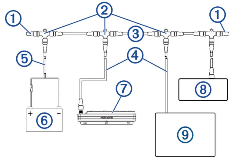
This diagram shows a sample installation which you can scale to apply to the NMEA 2000 network on your vessel. The device must receive power from a dedicated power connection and does not receive power from the NMEA 2000 network (Connecting to Power, page 4).
If you are unfamiliar with the needs of a NMEA 2000 network, you should read the “NMEA 2000 Network Fundamentals” chapter of the Technical Reference for NMEA 2000 Products. To download the reference, go to garmin.com/manuals/nmea_2000.
| Item | Description | Notes |
| NMEA 2000 terminator | NMEA 2000 terminators must connect to each end of the NMEA 2000 backbone. | |
| NMEA 2000 T-connector | NMEA 2000 T-connectors must connect to one another using the sides of each T, and they must connect to NMEA 2000 devices using drop cables connected to the top of each T. | |
| NMEA 2000 Backbone | ||
| NMEA 2000 drop cable | A NMEA 2000 drop cable connects a device to the NMEA 2000 network. A NMEA 2000 drop cable should not exceed 6 m (20 ft.). | |
| NMEA 2000 power cable | ||
|
|
12 V power source |
NOTICE
If you are using a Garmin Spectra LED control module with a 24 Vdc power source and LEDs, you must not connect the NMEA 2000 network to the 24 Vdc source. Connecting the NMEA 2000 network to a power source greater than 12 Vdc will damage connected devices. |
| NOTE: The NMEA 2000 network and all LED control modules should connect to the same ground location. | ||
| Garmin Spectra LED control module | The Garmin Spectra LED control module must connect to the NMEA 2000 network, to a power source, and to lighting devices to function correctly. | |
| Fusion stereo (optional) | The Fusion stereo must have a power connection separate from the NMEA 2000 network. | |
| Garmin chartplotter | The Garmin chartplotter must have a power connection separate from the NMEA 2000 network. |
Configuration
Before you can use lights connected to the Garmin Spectra LED control module, you must first configure each light using a Garmin chartplotter or through the ActiveCaptain app. Once configured, the LED lighting connected to the LED control module can be controlled through a compatible Garmin chartplotter or Fusion stereo connected to the same NMEA 2000 network as the LED control module.
NOTICE
Using certain LED colors, such as red and green, may violate the laws, regulations, and standards related to the use and/or operation of marine navigation lights. It is the user’s responsibility to comply with any such applicable laws, regulations, and standards. Garmin is not responsible for any fines, penalties, citations, or damages that may be incurred due to any such lack of compliance.
NOTE: If you have multiple chartplotters connected through a Garmin BlueNet™ network or Garmin Marine Network, each chartplotter must be connected to the same NMEA 2000 network as the Garmin Spectra LED control module to access lighting controls.
NOTE: If you have multiple stereos connected through a Fusion PartyBus™ network, each stereo must be connected to the same NMEA 2000 network as the Garmin Spectra LED control module to access lighting controls.
NOTE: If you have both chartplotters and stereos installed on the vessel, you must connect them all to the same Garmin BlueNet network or Garmin Marine Network and to the same NMEA 2000 network as the Garmin Spectra LED control module to synchronize lighting settings and behavior among all connected devices.
You can also configure LED lighting names, effects, and brightness levels. See the owner’s manual for your chartplotter or stereo for complete operational and configuration instructions.
Initializing Connected LED Lights Using a Chartplotter
Before you can interact with any connected LED lights using the chartplotter or stereo, you must first initialize the lights by providing information about the type of light source supported by the connected LEDs.
- From the lighting control screen on a compatible chartplotter connected to the same NMEA 2000 network as the Garmin Spectra LED control module, select Options > Advanced Settings > Lights.
A list of all available lights is shown. Any light indicated with a yellow circle and Not Used as the Light Output must be initialized before it’s available for use by the system. - Select a light from the list on the left.
- Select Light Output and select the type of LEDs connected:
- RGB: The connected dimmable LEDs support a full range of colors.
- RGBW: The connected dimmable LEDs support a full range of colors and high quality white light.
- CRGBW: The connected dimmable LEDs support a full range of colors and multiple temperature white light.
- Single Channel: The dimmable LEDs support one dedicated color.
TIP: You can select Identify to illuminate the selected light to help identify and test the selected LED type.
- Repeat this procedure for all connected lights until all of the intended LED lights are initialized.
LED Light Configuration for a Fusion Stereo Using the ActiveCaptain App
You can connect your mobile device to a compatible Fusion stereo using the ActiveCaptain app to configure and control lights connected to a Garmin Spectra LED control module. If the stereo and LED control module are connected to the same NMEA 2000 network as a compatible chartplotter, you should connect the ActiveCaptain app to the chartplotter instead of the stereo so you can use the full features included in the app in addition to the lighting controls. See the owner’s manual for the chartplotter for instructions.
NOTE: Before you can connect your mobile device to the stereo, you must either configure the stereo to act as a wireless access point or connect the stereo to a wireless router using an Ethernet cable.
Getting Started with the ActiveCaptain App
You can connect a mobile device to a compatible Fusion stereo using the ActiveCaptain app. The app provides a quick and easy way for you to configure and interact with the lights connected to a Garmin Spectra LED control module.

- If necessary, set up the stereo as a Wi‑Fi® access point or connect the stereo to a wireless router using an Ethernet cable.
- From the application store on your mobile device, install and open the ActiveCaptain app.
TIP: You can scan this QR code using your mobile device to download the app. - Log into the ActiveCaptain app using your Garmin account.
- Bring the mobile device within 32 m (105 ft.) of the stereo or the wireless router.
- In the ActiveCaptain app, select Connect.
- Select the SSID of the stereo or wireless router and provide the password, if necessary.
The app connects to the wireless network and returns to the main screen.
After the app connects to the wireless router or stereo correctly an option for Lighting is shown on the Boat Apps tab.
Initializing Connected LED Lights Using the ActiveCaptain App
Before you can interact with any connected LED lights using the stereo, you must first initialize the lights by providing information about the type of light source supported by the connected LEDs.
- If necessary, open the ActiveCaptain app and connect it to the stereo or wireless router.
- In the ActiveCaptain app, select Settings > Lighting.
A list of connected LED control modules is shown. - Select an LED control module with connected LED lights that you want to initialize and select Lights.
A list of all available lights is shown. Any light indicated with a yellow circle must be initialized before it’s available for use by the system. - Select a connected LED light from the list.
- Select Light Types and select the type of LEDs connected:
- RGB: The connected dimmable LEDs support a full range of colors.
- RGBW: The connected dimmable LEDs support a full range of colors and high quality white light.
- CRGBW: The connected dimmable LEDs support a full range of colors and multiple temperature white light.
- Single Channel: The dimmable LEDs support one dedicated color.
TIP: You can select Identify to illuminate the selected light to help identify and test the selected LED type.
- Repeat this procedure for all connected lights until all of the intended LED lights are initialized.
Associating LED Lights with an Audio Zone
If a Garmin Spectra LED control module is connected to the same NMEA 2000 network as a compatible Fusion stereo, you can associate connected lights with an audio zone. After lights are associated with an audio zone, you can configure the lights to synchronize with the music playing on the associated audio zone.
- Select an action:
- In the ActiveCaptain app, select Lighting > LIGHTS.
- From the lighting control screen on a connected Garmin chartplotter, select Options > Advanced Settings > Lights.
A list of lights connected to the LED control modules is shown.
- Select the LED lights that you want to configure, and select an action:
- In the ActiveCaptain app, select Advanced Settings > Audio Zones .
- On a Garmin chartplotter, select Select Audio Zone
A list of audio zones on all connected compatible Fusion stereos is shown.
- Select the audio zone to which you want to associate the lights.
Specifications
| Input voltage | 12 Vdc systems: From 10.8 to 16.0 Vdc
24 Vdc systems: From 21.6 to 32.0 Vdc |
| Fuse | LC102: 2 A slow-blow LC302: 6 A slow-blow |
| Operating temperature | From 0 to 50°C (From 32 to 122°F) |
| Storage temperature | From -20 to 70°C (From -4 to 158°F) |
| Water resistance | IP671 |
| Compass-safe distance | 20 cm (77/8 in.) |
| NMEA 2000 LEN | LEN 2 |
© 2024 Garmin Ltd. or its subsidiaries
Garmin®, the Garmin logo, Fusion®, and the Fusion logo, are trademarks of Garmin Ltd. or its subsidiaries, registered in the USA and other countries. These trademarks may not be used without the express permission of Garmin.
MN: A04495 / A04667
 IMPORTANT SAFETY AND PRODUCT INFORMATION
Product Environmental Programs
Information about the Garmin® product recycling program and WEEE, RoHS, REACH, and other compliance programs can be found at garmin.com/aboutGarmin/environment.
Declaration of Conformity
Hereby, Garmin declares that this product is in compliance with the Directive 2014/53/EU. The full text of the EU declaration of conformity is available at the following internet address: garmin.com/compliance.
UK Declaration of Conformity
Hereby, Garmin declares that this product is in compliance with the relevant statutory requirements. The full text of the declaration of conformity is available at the following internet address: garmin.com/compliance.
FCC Compliance
This device complies with part 15 of the FCC Rules. Operation is subject to the following two conditions:
- This device may not cause harmful interference, and
- This device must accept any interference received, including interference that may cause undesired operation.
This equipment has been tested and found to comply with the limits for a Class B digital device, pursuant to part 15 of the FCC rules. These limits are designed to provide reasonable protection against harmful interference in a residential installation. This equipment generates, uses, and can radiate radio frequency energy and may cause harmful interference to radio communications if not installed and used in accordance with the instructions. However, there is no guarantee that interference will not occur in a particular installation. If this equipment does cause harmful interference to radio or television reception, which can be determined by turning the equipment off and on, the user is encouraged to try to correct the interference by one of the following measures:
- Reorient or relocate the receiving antenna.
- Increase the separation between the equipment and the receiver.
- Connect the equipment into an outlet on a circuit different from that to which the receiver is connected.
- Consult the dealer or an experienced radio/TV technician for help.
This product does not contain any user-serviceable parts. Repairs should only be made by an authorized Garmin service center. Unauthorized repairs or modifications could result in permanent damage to the equipment, and void your warranty and your authority to operate this device under Part 15 regulations.
Consumer Limited Warranty
THIS LIMITED WARRANTY GIVES YOU SPECIFIC LEGAL RIGHTS, AND YOU MAY HAVE OTHER LEGAL RIGHTS, WHICH VARY FROM STATE TO STATE (OR BY COUNTRY OR PROVINCE). GARMIN DOES NOT EXCLUDE, LIMIT OR SUSPEND OTHER LEGAL RIGHTS YOU MAY HAVE UNDER THE LAWS OF YOUR STATE (OR COUNTRY OR PROVINCE). FOR A FULL UNDERSTANDING OF YOUR RIGHTS, YOU SHOULD CONSULT THE LAWS OF YOUR STATE, COUNTRY OR PROVINCE.
Non-aviation products are warranted to be free from defects in materials or workmanship for one year from the date of purchase. Within this period, Garmin will, at its sole option, repair or replace any components that fail in normal use. Such repairs or replacement will be made at no charge to the customer for parts or labor, provided that the customer shall be responsible for any transportation cost. This Limited Warranty does not apply to: (i) cosmetic damage, such as scratches, nicks and dents; (ii) consumable parts, such as batteries, unless product damage has occurred due to a defect in materials or workmanship; (iii) damage caused by accident, abuse, misuse, water, flood, fire, or other acts of nature or external causes; (iv) damage caused by service performed by anyone who is not an authorized service provider of Garmin; (v) damage to a product that has been modified or altered without the written permission of Garmin; (vi) damage to a product that has been connected to power and/or data cables that are not supplied by Garmin or damage to a product that has been connected to AC adapters and cables that are not certified by UL
(Underwriters Laboratories) and are not labeled as Limited Power Source (LPS). In addition, Garmin reserves the right to refuse warranty claims against products or services that are obtained and/or used in contravention of the laws of any country. Garmin navigation products are intended to be used only as a travel aid and must not be used for any purpose requiring precise measurement of direction, distance, location or topography. Garmin makes no warranty as to the accuracy or completeness of map data. This Limited Warranty also does not apply to, and Garmin is not responsible for, any degradation in the performance of any Garmin navigation product resulting from its use in proximity to any handset or other device that utilizes a terrestrial broadband network operating on frequencies that are close to the frequencies used by any Global Navigation Satellite System (GNSS) such as the Global Positioning Service (GPS). Use of such devices may impair reception of GNSS signals.
TO THE MAXIMUM EXTENT PERMITTED BY APPLICABLE LAW, THE WARRANTIES AND REMEDIES CONTAINED IN THIS LIMITED WARRANTY ARE EXCLUSIVE AND IN LIEU OF, AND GARMIN EXPRESSLY DISCLAIMS, ALL OTHER WARRANTIES AND REMEDIES, WHETHER EXPRESS, IMPLIED, STATUTORY, OR OTHERWISE, INCLUDING WITHOUT LIMITATION ANY IMPLIED WARRANTY OF MERCHANTABILITY OR FITNESS FOR A PARTICULAR PURPOSE, STATUTORY REMEDY OR OTHERWISE. THIS LIMITED WARRANTY GIVES YOU SPECIFIC LEGAL RIGHTS, AND YOU MAY HAVE OTHER LEGAL RIGHTS, WHICH VARY FROM STATE TO STATE AND FROM COUNTRY TO COUNTRY. IF IMPLIED WARRANTIES CANNOT BE DISCLAIMED UNDER THE LAWS OF YOUR STATE OR COUNTRY, THEN SUCH WARRANTIES ARE LIMITED IN DURATION TO THE DURATION OF THIS LIMITED WARRANTY. SOME STATES (AND COUNTRIES AND PROVINCES) DO NOT ALLOW LIMITATIONS ON HOW LONG AN IMPLIED WARRANTY LASTS, SO THE ABOVE LIMITATION MAY NOT APPLY TO YOU.
IN NO EVENT SHALL GARMIN BE LIABLE IN A CLAIM FOR BREACH OF WARRANTY FOR ANY INCIDENTAL, SPECIAL, INDIRECT OR CONSEQUENTIAL DAMAGES, WHETHER RESULTING FROM THE USE, MISUSE OR INABILITY TO USE THIS PRODUCT OR FROM DEFECTS IN THE PRODUCT. SOME STATES (AND COUNTRIES AND PROVINCES) DO NOT ALLOW THE EXCLUSION OF INCIDENTAL OR CONSEQUENTIAL DAMAGES, SO THE ABOVE LIMITATIONS MAY NOT APPLY TO YOU.
If during the warranty period you submit a claim for warranty service in accordance with this Limited Warranty, then Garmin will, at its option: (i) repair the device using new parts or previously used parts that satisfy Garmin’s quality standards, (ii) replace the device with a new device or a Garmin Recertified device that meets Garmin’s quality standards, or (iii) exchange the device for a full refund of your purchase price.
SUCH REMEDY SHALL BE YOUR SOLE AND EXCLUSIVE REMEDY FOR ANY BREACH OF WARRANTY. Repaired or replaced devices have a 90-day warranty. If the device sent in is still under its original warranty, then the new warranty is 90 days or to the end of the original 1-year warranty, whichever is longer.
Before seeking warranty service, please access and review the online help resources available on support.garmin.com. If your device is still not functioning properly after making use of these resources, contact a Garmin Authorized service facility in the original country of purchase or follow the instructions on support.garmin.com to obtain warranty service. If you are in the United States, you can also call 1-800-800-1020.
If you seek warranty service outside of the original country of purchase, Garmin cannot guarantee that the parts and products needed to repair or replace your product will be available due to differences in product offerings and applicable standards, laws and regulations. Accordingly, Garmin may, in its sole discretion and subject to applicable laws, repair your product with comparable parts or replace your product with a comparable Garmin product (new or a Garmin Recertified replacement), or require you to ship your product to a Garmin Authorized Service facility in the country of original purchase or to a Garmin Authorized service facility in another country that can service your product, in which case you will be responsible for complying with all applicable import and export laws and regulations and for paying all custom duties, V.A.T., shipping fees and other associated taxes and charges. In some cases, Garmin and its dealers may be unable to service your product in a country outside of the original country of purchase or return a repaired or replaced product to you in that country due to applicable standards, laws or regulations in that country.
Online Auction Purchases: Products purchased through online auctions are not eligible for rebates or other special offers from Garmin warranty coverage. Online auction confirmations are not accepted for warranty verification. To obtain warranty service, an original or copy of the sales receipt from the original retailer is required. Garmin will not replace missing components from any package purchased through an online auction.
International Purchases: A separate warranty may be provided by international distributors for devices purchased outside the United States depending on the country. If applicable, this warranty is provided by the local in-country distributor and this distributor provides local service for your device. Distributor warranties are only valid in the area of intended distribution. Devices purchased in the United States or Canada must be returned to the Garmin service center in the United Kingdom, the United States, Canada, or Taiwan for service Australian Purchases: Our goods come with guarantees that cannot be excluded under the Australian Consumer Law. You are entitled to a replacement or refund fora major failure and for compensation for any other reasonably foreseeable loss or damage. You are also entitled to have the goods repaired or replaced if the goods fail to be of acceptable quality and the failure does not amount to a major failure. The benefits under our Limited Warranty are in addition to other rights and remedies under applicable law in relation to the products. Garmin Australasia, 30 Clay Place, Eastern Creek, NSW 2766, Australia. Phone: 1800 235 822.
Documents / Resources
 |
GARMIN LC102 Spectra LED Control Module [pdf] Installation Guide LC102, LC302, LC102 Spectra LED Control Module, LC102, Spectra LED Control Module, LED Control Module, Control Module, Module |
 |
GARMIN LC102 Spectra LED Control Module [pdf] Instruction Manual LC102 Spectra LED Control Module, LC102, Spectra LED Control Module, LED Control Module, Control Module |


