FTDI FT4232HP Hi Speed USB Device with Type C Controller IC
Application Note
AN_551
FT4232HP_FT2232HP_FT232HP Configuration Guide
Version 1.2
Issue Date: 14-02-2025
Configuration guide for FT4232HP, FT2232HP, and FT232HP.
The FT4232HP/FT2232HP/FT232HP are high-speed USB devices with Type-C power delivery features. This document covers power delivery configuration options. For USB configurations, refer to AN_124 User Guide for FTDI FT_PROG Utility.
Use of FTDI devices in life support and/or safety applications is entirely at the user’s risk, and the user agrees to defend, indemnify, and hold FTDI harmless from any and all damages, claims, suits, or expense resulting from such use.
Future Technology Devices International Limited (FTDI)
Unit 1, 2 Seaward Place, Glasgow G41 1HH, United Kingdom
Tel.: +44 (0) 141 429 2777 Fax: + 44 (0) 141 429 2758
Web Site: http://ftdichip.com
Copyright © Future Technology Devices International Limited
1. Introduction
The FT4232HP/FT2232HP/FT232HP are high-speed USB devices with Type-C power delivery features. The power delivery functionality offers multiple configurable options, which are described in this document. However, it is important to note that this document only covers power delivery configuration options. For USB configurations, please refer to AN_124 User Guide for FTDI FT_PROG Utility.
1.1 Overview
This document provides a description of each configurable option and the corresponding configurable values for each parameter in the EEPROM of the FT4232HP/FT2232HP/FT232HP. The EEPROM is an external component and is only necessary if a custom configuration is required for the design. If the default configuration is suitable, then an EEPROM is not needed. For default values, please refer to the sections below.
1.2 Glossary of Terms
| S/N | Term | Description | ||||||||||||||
| 1 | Sink / Consumer | When the device is consuming power from the host port, the device is said to be in “Sink” mode or device is said to be a “consumer”. | ||||||||||||||
| 2 | Source / Provider | When the device is supplying power to the host, then the device is operating in “Source” mode. The device can change the role from Sink to Source if the device is self-powered and power role swap is enabled in the configuration. |
||||||||||||||
| 3 | Power Role Swap | The process of changing the role is called role swap. The device has the capability to switch the role from Sink to Source if the device is self-powered. | ||||||||||||||
2. Configuration Parameters
256 bytes in the configuration EEPROM are reserved for configuration options. Table 1 gives the information for all the configurable options.
| Parameter | Description | Default value | Configurable values | |||||||||||||
| Sink Request Power Role Swap | Sink will initiate a PR SWAP request only if this option is set. Default settings do not support PR SWAP. However, if the device is self-powered, then PR SWAP can be supported by modifying the configurations. |
0 – Disabled. | 0 – Disabled. 1 – Enabled. |
|||||||||||||
| Sink Accept PR Swap | Option to accept PR SWAP when FT4232HP /FT2232HP/FT232HP is a sink. If this option is not set, PR_SWAP request from a source will be rejected |
0 – Reject. | 0 – Reject. 1 – Accept. |
|||||||||||||
| Source Request PR SWAP | When the device is a Source, this option is used to decide whether to swap back to sink when it sees a Port2 disconnect event. |
0 – Disabled. | 0 – Disabled. 1 – Enabled. |
|||||||||||||
| Source Accept PR SWAP | When the device is a source, a PR_SWAP request from sink can be accepted or rejected based on this option. | 0 – Reject. | 0 – Reject. 1 – Accept. |
|||||||||||||
| External MCU | This is to switch over to external MCU mode. | 0 – Internal MCU. | 0 – Internal MCU. 1 – External MCU. |
|||||||||||||
| PD Auto Clock | Auto clock enable / disable. Auto clock feature is explained in section 2.3. |
0 – Disabled. | 0 – Disabled. 1 – Enabled. |
|||||||||||||
| Use EFUSE | This option indicates whether to use trim values from EFUSE or not. Keep this enabled always. Configurable option is provided for characterization purpose only. | 1 – Use EFUSE. | 0 – Do not use EFUSE TRIM. 1 – Use EFUSE TRIM | |||||||||||||
| FRS | Fast Role Swap | ‘FRS DISABLED’ | ‘FRS DISABLED’ ‘Default USB Power’ ‘1.5A@5V’ ‘3A@5V’ |
|||||||||||||
| FRS Threshold | Voltage drop threshold to trigger the FRS | 4680 | 4680 4368 4056 |
|||||||||||||
| EXTEND_ISET | Not used by default. In a Sink-only configuration, more pins can be used as ISETS. By enabling this option, will give more ISETs to choose from. |
0 | 0 – Extended ISET not used. 1 – Extended ISET used. | |||||||||||||
| Parameter | Description | Default value | Configurable values | |||||||||||||
| ISET_ENABLED | Bit to enable / disable ISET feature. | 1 | 0 – Disable the ISET feature. All the above ISET fields will be ignored. 1 – ISET Enabled. |
|||||||||||||
| GPIO 0 | Configuration option for GPIO 0. | ‘N/A’ | Please refer to the tables Table 3 and Table 4 for the available configuration options for each GPIO. If this field is unused, then select ‘NA’. |
|||||||||||||
| GPIO 1 | Configuration option for GPIO 1 | ‘N/A’ | Please refer to the tables Table 3 and Table 4 for the available configuration options for each GPIO. If this field is unused, then select ‘NA’. |
|||||||||||||
| GPIO 2 | Configuration option for GPIO 2 | ‘PD1_LOAD_EN’ | Please refer to the tables Table 3 and Table 4 for the available configuration options for each GPIO. If this field is unused, then select ‘NA’. |
|||||||||||||
| GPIO 3 | Configuration option for GPIO 3 | ‘ISET3’ | Please refer to the tables Table 3 and Table 4 for the available configuration options for each GPIO. If this field is unused, then select ‘NA’. |
|||||||||||||
| Sink PDO1 | Voltage and current profile for PDO1. Typically, PDO1 is vSafe5. | Voltage in 1mV Unit – 5000 (5V). And in 50mV Steps. Current in 1mA Unit – 3000 |
Voltage – 5000 (5V) Current – (0-5000) (0-5A) | |||||||||||||
| Parameter | Description | Default value | Configurable values | |||||||||||||
| (3A), 10mA Steps. | ||||||||||||||||
| Sink PDO2 | Voltage and current profile for PDO2. | 0 | 0 Means this profile is not used. User is allowed to configure the profile to any valid voltage / current value without conflicting. A valid profile is a unique profile (Same voltage profile as another PDO not allowed – Also the profiles should be in the descending order of voltage). |
|||||||||||||
| Sink PDO3 | Voltage and current profile for PDO3. | 0 | Same as above. | |||||||||||||
| Sink PDO4 | Voltage and current profile for PDO4. | 0 | Same as above. | |||||||||||||
| Sink PDO5 | Voltage and current profile for PDO5. | 0 | Same as above. | |||||||||||||
| Sink PDO6 | Voltage and current profile for PDO6. | 0 | Same as above. | |||||||||||||
| Sink PDO7 | Voltage and current profile for PDO7. | 0 | Same as above. | |||||||||||||
| Source PDO1 | Voltage and current profile for PDO1. Typically, PDO1 is vSafe5. Default Setting does not have source capability. |
Voltage in 1mV Unit – 5000 (5V). And in 50mV Steps. Current in 1mA Unit – 300 (3A), 10mA Steps. |
Voltage – 5000 (5V) Current – (0- 5000) (0-5A) |
|||||||||||||
| Source PDO2 | Default Setting does not have source capability. | Voltage in 50mV Unit – 0. Current in 10mA Unit – 0 |
||||||||||||||
| Source PDO3 | Default Setting does not have source capability. | Voltage in 50mV Unit – 0. Current in 10mA Unit – 0 |
||||||||||||||
| Source PDO4 | Default Setting does not have source capability. | Voltage in 50mV Unit – 0. Current in 10mA Unit – 0 |
||||||||||||||
| I2C Address | Used for external MCU. | 32 (0x20) | Any Valid address. | |||||||||||||
| TRIM1 | Do not use this in production. Set to 0. |
0 | ||||||||||||||
| TRIM2 | Do not use this in Production. | 0 | ||||||||||||||
| Parameter | Description | Default value | Configurable values | |||||||||||||
| Set to 0. | ||||||||||||||||
| External DC | This option indicates the device is self-powered and has a fixed External power supply. FT4232HP/FT2232HP/FT232HP does not support power role swap in its default settings as role swap feature needs a power supply. So, if the device is externally powered, then power role swap can be supported. Use this option to indicate externally powered device. |
UNCHECK | CHECKBOX | |||||||||||||
2.1 Power Role Swap Options
There are four different combinations for power role swap. These are the four configurable options available.
1. Sink Request Power Role (PR) Swap
When this option is set, the sink initiates a power role swap request if the device is self-powered. The “External DC” option indicates whether the device is self-powered.
2. Sink Accept PR Swap
If the device receives a PR_SWAP request from the source, the sink can reject or accept it based on this option. This option should be set only if the device is powered externally through a DC power supply.
3. Source Request PR SWAP
This option does not apply to single-port devices.
4. Source Accept PR SWAP
Similarly, the device (source) can return to the sink if the current sink requests a PR_SWAP. This option determines whether to accept the request or not.
2.2 External MCU
The device comes with a default Type-C and PD state machine. If the features provided by this internal state machine do not meet the customer’s requirements, the customer has the option to implement their own state machines and additional features using the I2C slave interface available on the Customer MCU.
When using such solution, this “External MCU” option should be set if there is an EEPROM available. If no EEPROM, then GPIO_0, GPIO_1 can be pulled high to indicate the same.
2.3 PD Auto Clock
To aid in power saving, the clock can be turned off to the PD device when there is no activity. With auto clock option enabled, the clock will turn on whenever there is any activity to the PD device and will turn off after the activity.
2.4 Use EFUSE
The PD device has an internal EFUSE block, and its size is 64bits. This EFUSE is programmed during the IC characterization time, and it is one time programmable. The value programmed in this block is used by the software to program bandgap voltage, pull up current, pull down resistance etc. “Use EFUSE” option is enabled by default. Software uses the EFUSE value only if this option is enabled. For debugging purpose, this option can be disabled but not recommended to disable it for production.
2.5 FRS
This option allows you to enable or disable Fast Role Swap (FRS). The device can quickly switch from a source to a sink. When this option is enabled, the device can switch back to the sink without causing a disconnection on the USB interface.
2.6 FRS Threshold
This option takes the threshold voltage for the FRS. The default is 4680mV. When the voltage drops below this level triggers an FRS.
2.7 ISET
The ISET pins indicate the available power profiles. By default, there are three options: ISET1, ISET2, and ISET3. However, enabling the EXTEND_ISET option will make additional ISET pins available. The table below shows the ISET options.
| ISET Pin | Meaning | Remarks | ||||||||||||||
| ISET1 | TYPE-C 5V 1P5A Profile | Optional. | ||||||||||||||
| ISET2 | TYPE-C 5V 3A Profile | Optional. | ||||||||||||||
| ISET3 | PDO1 Profile | Typically, 5V3A profile. If 5V3A, then ISET2 can be left unassigned so that FT_Prog will internally make ISET2 same as ISET3. | ||||||||||||||
| ISET4 | PDO2 Profile | Available in Sink-only use case when the EXTEND_ISET option is set in the configuration. | ||||||||||||||
| ISET5 | PDO3 Profile | Available in Sink-only use case when the EXTEND_ISET option is set in the configuration. | ||||||||||||||
| ISET6 | PDO4 Profile | Available in Sink-only use case when the EXTEND_ISET option is set in the configuration. | ||||||||||||||
2.8 EXTEND_ISET
When the device is in sink-only mode, more GPIO pins are available for use as ISET. As seen in the figure below, more ISET pins are in the GPIO dropdown list.
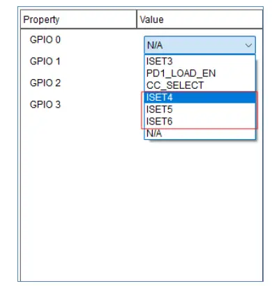
Figure 1 – GPIO Dropdown shows more ISET options when EXTEND_ISET is enabled
2.9 ISET_ENABLED
All the ISET related fields are valid only if this field is enabled. Instead of changing multiple ISET fields, this single enable/disable option helps to enable/disable the ISET feature.
2.10 GPIO 0 to GPIO 3
These are the 4 configurable GPIOs. Depending on the configuration options, these pins can be configured to use any of the options from the table below.
The Load Enable function (PD1_LOAD_EN) can drive a status LED or control the load switch circuit used to route VBUS power to the customer’s hardware.
| Options | Description | |||||||||||||||
| ISET1 | TypeC 5V 1P5A Profile | |||||||||||||||
| ISET2 | TypeC 5V 3A Profile | |||||||||||||||
| ISET3 | PDO1 Profile (5V3A) | |||||||||||||||
| PD1_LOAD_EN | PD1 Load Enable Pin | |||||||||||||||
| CC_SELECT | CC Selector Indicator | |||||||||||||||
| ISET4 | PDO2 Profile | |||||||||||||||
| Sink-only Configuration | ||||||||||||||||
| Options | Description | |||||||||||||||
| ISET5 | PDO3 Profile | |||||||||||||||
| ISET6 | PDO4 Profile | |||||||||||||||
Table 3 – Options for Sink-only Configuration
When the External DC option is enabled in the configuration, the device can also support power role swapping and change the role to the source. With this option enabled, the GPIO configuration supports the following options in the table below. However, the DC power supply must always be present. In other words, the device must always be self-powered when this option is on.
| Dual Role Options | ||||||||||||||||
| Options | Description | |||||||||||||||
| ISET1 | TypeC 5V 1P5A Profile | |||||||||||||||
| ISET2 | TypeC 5V 3A Profile | |||||||||||||||
| ISET3 | PDO1 Profile (5V3A) | |||||||||||||||
| PD1_LOAD_EN | PD1 Load Enable Pin | |||||||||||||||
| DISCHARGE | Discharge Pin | |||||||||||||||
| CC_SELECT | CC Selector Indicator | |||||||||||||||
| PS_EN | Power Supply Enable Pin, also supplies 5V which is PDO1 Source Profile | |||||||||||||||
| P1 | Source Pin for PDO2 | |||||||||||||||
| P2 | Source Pin for PDO3 | |||||||||||||||
| P3 | Source Pin for PDO4 | |||||||||||||||
Table 4 – Options for Dual Role Mode
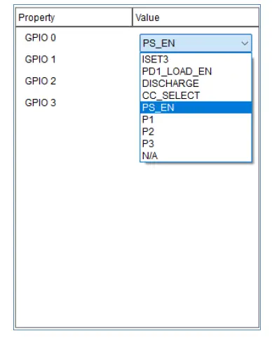
Figure 2 – GPIO Configuration options when external DC is enabled
For a Sink-only use case, the extended ISET option can select additional pins as ISET.
The power swap options should be disabled to make the device in sink-only mode. The below picture shows the various options available in Sink-only use case.

Figure 3 – ISET Options
2.11 Sink PDO [1:7]
Option to select Voltage and Current Profile for Sink PDO1.
Corresponding to every PDO option, there is a voltage dropdown box and a current dropdown box in FT_PROG. Please select the voltage and current from this list for the PDO.
The lowest voltage profile should be PDO1 and the second lowest should be PDO2 and so on. Basically, the PDO profile should be in ascending order with respect to the voltage.
2.12 Source PDO [1:4]
Option to select Voltage and Current Profile for Source PDO1.
Corresponding to every PDO option, there is a voltage dropdown box and a current dropdown box in FT_PROG. Please select the voltage and current from this list for the PDO.
The lowest voltage profile should be PDO1 and the second lowest should be PDO2 and so on. Basically, the PDO profile should be in ascending order with respect to the voltage.
2.13 I2C Address
This is used for the case of an external MCU. The I2C address will default to 0x20 if this is not specified.
2.14 TRIM1
For Debug purpose only – Usually the TRIM values are taken from EFUSE. However, EFUSE can be overridden using this field.
2.15 TRIM2
For Debug purpose only – Usually the TRIM values are taken from EFUSE. However, EFUSE can be overridden using this field.
2.16 External DC
If the device is self-powered, then this option can be set to initiate a power role swap request to switch over the role to source. Sink Request power role swap option also should be set along with this to achieve this.
3. Contact Information
Head Office – Glasgow, UK
Future Technology Devices International Limited (UK)
Unit 1, 2 Seaward Place, Centurion Business Park
Glasgow G41 1HH
United Kingdom
Tel: +44 (0) 141 429 2777
Fax: +44 (0) 141 429 2758
E-mail (Sales)sales1@ftdichip.com
E-mail (Support)support1@ftdichip.com
E-mail (General Enquiries)admin1@ftdichip.com
Branch Office – Tigard, Oregon, USA
Future Technology Devices International Limited (USA) 7130 SW Fir Loop
Tigard, OR 97223-8160
USA
Tel: +1 (503) 547 0988
Fax: +1 (503) 547 0987
E-mail (Sales)us.sales@ftdichip.com
E-mail (Support)us.support@ftdichip.com
E-mail (General Enquiries)us.admin@ftdichip.com
Branch Office – Taipei, Taiwan
Future Technology Devices International Limited (Taiwan) 2F, No. 516, Sec. 1, NeiHu Road
Taipei 114
Taiwan, R.O.C.
Tel: +886 (0) 2 8797 1330
Fax: +886 (0) 2 8751 9737
Branch Office – Shanghai, China
Future Technology Devices International Limited (China) Room 1103, No. 666 West Huaihai Road,
Shanghai, 200052
China
Tel: +86 (21) 62351596
Fax: +86 (21) 62351595
Distributor and Sales Representatives
Please visit the Sales Network page of the FTDI Web site for the contact details of our distributor(s) and sales representative(s) in your country.
System and equipment manufacturers and designers are responsible to ensure that their systems, and any Future Technology Devices International Ltd (FTDI) devices incorporated in their systems, meet all applicable safety, regulatory and system-level performance requirements. All application-related information in this document (including application descriptions, suggested FTDI devices and other materials) is provided for reference only. While FTDI has taken care to assure it is accurate, this information is subject to customer confirmation, and FTDI disclaims all liability for system designs and for any applications assistance provided by FTDI. Use of FTDI devices in life support and/or safety applications is entirely at the user’s risk, and the user agrees to defend, indemnify, and hold harmless FTDI from any and all damages, claims, suits, or expense resulting from such use. This document is subject to change without notice. No freedom to use patents or other intellectual property rights is implied by the publication of this document. Neither the whole nor any part of the information contained in, or the product described in this document, may be adapted, or reproduced in any material or electronic form without the prior written consent of the copyright holder. Future Technology Devices International Ltd, Unit 1, 2 Seaward Place, Centurion Business Park, Glasgow G41 1HH, United Kingdom. Scotland Registered Company Number: SC136640
Appendix A – References
Document References
AN_124 User Guide for FTDI FT_PROG Utility
FT_PROG
https://usb.org/sites/default/files/USB%20Power%20Delivery_1.zip USB High Speed Series ICs
Acronyms and Abbreviations
| Terms | Description | |||||||||||||||
| BM | Bit Map | |||||||||||||||
| BOS | Binary Object Store | |||||||||||||||
| GPIO | General Purpose Input Output | |||||||||||||||
| PD | Power Delivery | |||||||||||||||
| PDO | Power Delivery Object | |||||||||||||||
| PR SWAP | Power Role Swap. | |||||||||||||||
| USB | Universal Serial Bus | |||||||||||||||
| USB-IF | USB Implementers Forum | |||||||||||||||
Appendix C – Revision History
Document Title: AN_551 FT4232HP_FT2232HP_FT232HP Configuration Guide
Document Reference No.: FT_001493
Clearance No.: FTDI#562
Product Page: USB High Speed Series ICs
Document Feedback: Send Feedback
| Revision | Changes | Date | ||||||||||||||
| 1.0 | Initial Release. | 06-05-2021 | ||||||||||||||
| 1.1 | Minor editorial changes for the new release version. | 28-11-2023 | ||||||||||||||
| 1.2 | Updates for improved user experience in FT_Prog. FT_Prog has been updated with a simpler GPIO configuration, and the document has been updated to reflect the same. Bitmap options and GPIO multiplexing have been removed. Added tables for various GPIO configurations. Added example screenshots of FT_Prog. |
14-02-2025 | ||||||||||||||
Specifications:
- Product Models: FT4232HP, FT2232HP, FT232HP
- Version: 1.2
- Issue Date: 14-02-2025
- Power Delivery: Type-C
FAQ
Q: Do I need an EEPROM for default configurations?
A: No, an EEPROM is only necessary for custom configurations.
Default values are available in the document.
Q: Can the device change its power role?
A: Yes, the device can change from Sink to Source if self-powered and power role swap is enabled.
Documents / Resources
 |
FTDI FT4232HP Hi Speed USB Device with Type C Controller IC [pdf] User Guide FT4232HP, FT2232HP, FT232HP, FT4232HP Hi Speed USB Device with Type C Controller IC, FT4232HP, Hi Speed USB Device with Type C Controller IC, Type C Controller IC, Controller IC |


