FRIGIDAIRE FG7TC Two Stage Variable Speed Condensing Upflow Horizontal Gas Furnaces

Introduction
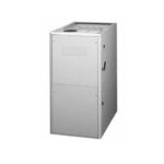
Two Stage, Variable Speed, Condensing Up flow/Horizontal Gas Furnaces
Induced Draft – 95.1 AFUE
Input 60,000 – 120,000 Btuh
The high efficiency up flow gas furnace may be installed free standing in a utility room, basement, or enclosed in an alcove or closet. Up flow/horizontal units come ready for up flow or horizontal application. The extended flush jacket provides a pleasing “appliance appearance.” Design certified by CSA for application in Canada and the United States.
This furnace series is approved and certified by the SCAQM and the SJVAPC Districts in the state of California under each Districts’ Mitigation Fee Plan for shipment into and sales in both districts.
For California installations in SCAQMD only: This furnace does not meet the SCAQMD Rule 1111 NOx emission limit (14 ng/J), and thus is subject to a mitigation fee of up to $450. This furnace is not eligible for the Clean Air Furnace Rebate Program: www.CleanAirFurnaceRebate.com.
FEATURES AND BENEFITS
- Variable Speed Direct Drive Blower: Energy-efficient, brushless DC (ECM) motor controls airflow to provide better temperature control, humidity control and air distribution.
- 100% fired and tested: All units and each component are tested on the manufacturing line.
- Best packaging in the industry: Unique corner post design assures product will arrive to the homeowner dent free.
- 30 second blower delay: At start-up assures a warm duct temperature at furnace start-up. Adjustable blower off settings (60, 90, 120 and 180 seconds).
- 30 second post purge: Increases life of heat exchanger.
- Two Stage Inducer: Optimizes efficiency on first stage heat and reduces sound levels.
- Hot surface igniter: Innovative application of a silicon nitride type igniter. Utilizes proven Smart lite® technology.
- Color coded wire harness: Designed to fit the components, all with quick-connect fittings for ease of service and replacement.
- Flexible category IV venting system: May be vertically or horizontally vented using either a one-pipe or two-pipe system for maximum flexibility in installation.
- High Static Blowers: All models equipped with high static blowers.
- Low Boy Height: Easy to apply in low ceiling applications, works well with taller high SEER coils, easier to handle and install.
- Tubular primary heat exchanger: Heavy gauge aluminized steel heat exchanger and stainless steel secondary heat exchanger assures a long life.
- 60 second fixed cooling cycle blower-off delay (TDR): Increases cooling performance when matched with a Nortek Global HVAC coil.
- LP convertible: Simple burner orifice and regulator spring change for ease of convertibility.
- Diagnostic lights for easy troubleshooting without counting flashes: Dedicated light for flame signal strength and 2 lights in combination to indicate all other fault codes with easy to recognize states without counting flashes.
- Incorporates integrated control board: With connections for electronic air cleaner and humidifier. Ergonomically located for ease of service.
- Two piece door design: Enhances furnace appearance and uses captured screws to prevent losing door screws.
- Blower Compartment: Sealed door to reduce air leakage and insulated for ultra quiet operation.
- Sealed Vestibule: Reduces burner and inducer sound levels.
- Furnace Air Leakage: These furnaces comply with Energy Star cabinet air leakage requirement of less than or equal to 2%. Keep the conditioned air flowing to where it’s needed.
- PolyPro by DuraVent: These furnaces have been tested with and are approved to be installed with DuraVent’s PolyPro venting system.
LOCATION OF FURNACE COMPONENTS
UPFLOW / HORIZONTAL FURNACE (*TC SERIES)

DIMENSIONS
| *TC Model #’s | Dimension “A” | Dimension “B” | Dimension “C” |
| 060D-VB | 17 1/2 | 15 7/8 | 16 1/8 |
| 080D-VC | 21 | 19 3/8 | 19 5/8 |
| 100D-VC | |||
| 120D-VD | 24 1/2 | 22 7/8 | 23 1/8 |
FG7TC 95.1+ High Efficiency Up flow/Horizontal Series

G7TC, VSHE (B CABINET)
| HEATING AIRFLOW (CFM) & TEMPERATURE RISE (° F) | ||||||
| MODEL NUMBER/ HEATING INPUT | MOTOR SWITCH SETTINGS (0=OFF, 1=ON) | CFM | RISE | |||
| 1 | 2 | 3 | 4 | |||
| G7TC-060D-V24B 60,000 BTU/hr | ||||||
| 1 | 0 | 0 | 0 | 1,000 | 53 | |
| 1 | 0 | 0 | 1 | 1,100 | 48 | |
| 1 | 0 | 1 | 0 | 1,200 | 44 | |
| 1 | 0 | 1 | 1 | 1,300 | 41 | |
| 1 | 1 | 0 | 0 | 1,400 | 38 | |
| 1 | 1 | 0 | 1 | |||
| 1 | 1 | 1 | 0 | |||
| 1 | 1 | 1 | 1 | |||
| COOLING AIRFLOW (CFM) | |||||||
| MOTOR SWITCH SETTINGS (0=OFF, 1=ON) | CFM | NOMINAL AC / HP CAPACITY | |||||
| 1 | 5 | 6 | 7 | 8 | LOW | HIGH | |
| 1 | 0 | 0 | 0 | 0 | 470 | 700 |
|
| 1 | 0 | 0 | 0 | 1 | 510 | 760 | |
| 1 | 0 | 0 | 1 | 0 | 550 | 820 | |
| 1 | 0 | 0 | 1 | 1 | 590 | 880 | |
| 1 | 0 | 1 | 0 | 0 | 630 | 940 | |
| 1 | 0 | 1 | 0 | 1 | 670 | 1,000 | |
| 1 | 0 | 1 | 1 | 0 | 710 | 1,060 | |
| 1 | 0 | 1 | 1 | 1 | 750 | 1,120 | |
| 1 | 1 | 0 | 0 | 0 | 790 | 1,180 | |
| 1 | 1 | 0 | 0 | 1 | 830 | 1,240 | |
| 1 | 1 | 0 | 1 | 0 | 870 | 1,300 | |
| 1 | 1 | 0 | 1 | 1 | 910 | 1,360 | |
| 1 | 1 | 1 | 0 | 0 | 950 | 1,420 | |
| 1 | 1 | 1 | 0 | 1 | 990 | 1,480 | |
| 1 | 1 | 1 | 1 | 0 | 1,030 | 1,540 | |
| 1 | 1 | 1 | 1 | 1 | 1,070 | 1,600 | |
NOTES:
- Motor switch settings for heating speeds use HEAT switches 1, 2, 3, & 4 and for cooling speeds use COOL switches 5, 6, 7, & 8.
- To comply with government mandated efficiency standards, two openings are required for airflows above 1,600 CFM.
- Data is shown without filter.
- Temperature rises in the table are approximate. Actual temperature rises may vary.
- Individual cells shaded in gray indicate a temperature rise outside of the recommended range.
- To comply with government mandated efficiency standards, speed settings shaded in gray are not allowed in HEAT mode.
- When in low stage heat, the airflow is approximately 70% of the tables high value (2-stage furnaces only).
G7TC, VSHE (C CABINET)
| HEATING AIRFLOW (CFM) & TEMPERATURE RISE (°F) | ||||||||
| MODEL NAME/ HEATING INPUT | MOTOR SWITCH SETTINGS (0=OFF, 1=ON) | 080D-V35C 80,000 BTU/hr |
100D-V35C 100,000 BTU/hr |
|||||
| 1 | 2 | 3 | 4 | CFM | RISE | CFM | RISE | |
| G7TC- | ||||||||
| # | 0 | 0 | 0 | |||||
| # | 0 | 0 | 1 | 1,115 | 63 | |||
| # | 0 | 1 | 0 | 1,230 | 57 | |||
| # | 0 | 1 | 1 | 1,345 | 52 | 1,345 | 65 | |
| # | 1 | 0 | 0 | 1,460 | 48 | 1,460 | 60 | |
| # | 1 | 0 | 1 | 1,575 | 44 | 1,575 | 56 | |
| # | 1 | 1 | 0 | 1,690 | 41 | 1,690 | 52 | |
| # | 1 | 1 | 1 | |||||
| COOLING AIRFLOW (CFM) | |||||||||||||
| MOTOR SWITCH SETTINGS (0=OFF, 1=ON) | CFM | NOMINAL AC / HP CAPACITY | |||||||||||
| 1 | 5 | 6 | 7 | 8 | LOW | HIGH | |||||||
| # | 0 | 0 | 0 | 0 | 685 | 1,025 | 2.5 TON | ||||||
| # | 0 | 0 | 0 | 1 | 730 | 1,090 | 3 TON | ||||||
| # | 0 | 0 | 1 | 0 | 775 | 1,155 | |||||||
| # | 0 | 0 | 1 | 1 | 815 | 1,220 | |||||||
| # | 0 | 1 | 0 | 0 | 860 | 1,285 | 3.5 TON | ||||||
| # | 0 | 1 | 0 | 1 | 905 | 1,350 | |||||||
| # | 0 | 1 | 1 | 0 | 950 | 1,415 | 4 TON | ||||||
| # | 0 | 1 | 1 | 1 | 990 | 1,480 | |||||||
| # | 1 | 0 | 0 | 0 | 1,035 | 1,545 | |||||||
| # | 1 | 0 | 0 | 1 | 1,080 | 1,610 | |||||||
| # | 1 | 0 | 1 | 0 | 1,120 | 1,675 | 5 TON | ||||||
| # | 1 | 0 | 1 | 1 | 1,165 | 1,740 | |||||||
| # | 1 | 1 | 0 | 0 | 1,210 | 1,805 | |||||||
| # | 1 | 1 | 0 | 1 | 1,255 | 1,870 | |||||||
| # | 1 | 1 | 1 | 0 | 1,295 | 1,935 | |||||||
| # | 1 | 1 | 1 | 1 | 1,340 | 2,000 | |||||||
NOTES:
- Motor switch settings for heating speeds use HEAT switches 1, 2, 3, & 4 and for cooling speeds use COOL switches 5, 6, 7, & 8.
- To comply with government mandated efficiency standards, two openings are required for airflows above 1,600 CFM.
- Data is shown without filter.
- Temperature rises in the table are approximate. Actual temperature rises may vary.
- Individual cells shaded in gray indicate a temperature rise outside of the recommended range.
- To comply with government mandated efficiency standards, speed settings shaded in gray are not allowed in HEAT mode.
- When in low stage heat, the airflow is approximately 70% of the tables high value (2-stage furnaces only).
VENTING
All models are approved for vertical non direct (1 pipe) and direct (2 pipe) venting applications. See Vent Table below for specified sizes and allowable lengths.
VENT TABLE
| FURNACE MODELS (BTU) | FURNACE INSTALLATION | SINGLE PIPE LENGTH (FT.) with 1 long radius elbow** | DIRECT VENT, DUAL PIPE LENGTH (ft.) WITH 1 long radius elbow on each pipe** | ||
| OUTLET | OUTLET | INLET/OUTLET | INLET/OUTLET | ||
| 2” Diameter | 3” Diameter | 2” Diameter | 3” Diameter | ||
| 60,000 | Up flow | 90 | 90 | 90 | 90 |
| Horizontal | 50 | 90 | 50 | 90 | |
| 80,000 | Up flow | 40 | 90 | 40 | 90 |
| Horizontal | 30 | 90 | 30 | 90 | |
| 100,000 | Up flow | 30 | 90 | 30 | 90 |
| Horizontal | 30 | 90 | 30 | 90 | |
| 120,000 | Up flow | N/A | 90 | N/A | 90 |
| Horizontal | N/A | 90 | N/A | 90 | |
*NOTES:
- Subtract 2.5 ft. for each additional 2 inch long radius elbow, 5 ft. for each additional 2 inch short radius elbow, 3.5 ft. for each additional 3 inch long radius elbow, and 7 ft. for each additional 3 inch short radius elbow. Subtract 5ft for each 2” tee and 8ft for each 3” tee.
- Two 45 degree elbows are equivalent to one 90 degree elbow.
- This table applies for elevations from sea level to 2,000 ft. For higher elevations, decrease pipe lengths by 8% per 1,000 ft of altitude
MODEL IDENTIFICATION CODE

SPECIFICATIONS
| FG7TC MODEL NUMBERS | -060D-V24B1 | -080D-V35C1 | -100D-V35C1 |
| Input – Btuh (a) | 60000 / 39000 | 80000 / 52000 | 100000 / 65000 |
| Heating Capacity – BtuH | 57000 / 37000 | 76000 / 49000 | 95000 / 62000 |
| AFUE | 95.0 | 95.0 | 95.0 |
| Motor H.P. – Speed – Type | 3/4 – Variable | 1 – Variable | 1 – Variable |
| Motor FLA | 8.8 | 11.5 | 11.5 |
| Rated Ext. SP – In. W.C. | 0.50 | 0.50 | 0.50 |
| Temperature Rise Range – F | 30-60 | 35-65 | 35-65 |
| Shipping Weights | 120 lb | 140 lb | 145 lb |
| SKU | 1025924F | 1025925F | 1025926F |
Note:
All models are 115V, 60 Hz. Gas Connections are 1/2″ N.P.T. AFUE = Annual Fuel Utilization Efficiency
(a) Ratings to 2,000 ft. Over 2,000 ft. reduce 4% for each 1,000 ft. above sea level.
ACCESSORIES
| FG7TC KITS | |
| Description | SKU |
| 2″ Concentric Vent Kit, US approved only | 904177 |
| 3″ Concentric Vent Kit, US approved only | 904176 |
| 2″ Concentric Vent Kit, Canadian and US approved | 904952 |
| 3″ Concentric Vent Kit, Canadian and US approved | 904953 |
| 2″ Side Wall Vent Kit | 904617 |
| 3″ Side Wall Vent Kit | 904347 |
| U.S. LP Conversion Kit (0 to 10,000 ft.) | 905028 |
| Canada LP Conversion Kit (0 to 4,500 ft.) | 905029 |
| Bottom Return Filter 20 per Box, “A” Cabinet | 903088 |
| Bottom Return Filter 20 per Box, “B” Cabinet | 904916 |
| Bottom Return Filter 20 per Box, “C” Cabinet | 904917 |
| Bottom Return Filter 20 per Box, “D” Cabinet | 904918 |
| Side Return Filter Kit | 541036 |
| Neutralizer Kit | 902377 |
GENERAL TERMS OF LIMITED WARRANTY
Nortek Global HVAC, LLC will furnish a replacement for any part of this product which fails in normal use and service within the terms and conditions of the warranty.
For complete details of the Limited Warranty, including applicable terms and conditions, see your local installer or contact the Nortek Global HVAC, LLC warranty department for a copy.
Before purchasing this appliance, read important energy cost and efficiency information available from your retailer. Specifications and illustrations subject to change without notice and without incurring obligations. Printed in U.S.A (06/2019)
Customer Support
472F-0619
www.frigidairehvac.com
FRIGIDAIRE is a registered trademark of Electrolux Home Products Inc. and used under a license from Electrolux Home Products, Inc. © Nortek Global HVAC, LLC. All Rights Reserved.


Documents / Resources
 |
FRIGIDAIRE FG7TC Two Stage Variable Speed Condensing Upflow Horizontal Gas Furnaces [pdf] User Manual FG7TC Two Stage Variable Speed Condensing Upflow Horizontal Gas Furnaces, FG7TC, Two Stage Variable Speed Condensing Upflow Horizontal Gas Furnaces, Variable Speed Condensing Upflow Horizontal Gas Furnaces, Condensing Upflow Horizontal Gas Furnaces, Upflow Horizontal Gas Furnaces, Gas Furnaces, Furnaces |