![]()
![]() REV.: 20240925
REV.: 20240925
Guide # 117041
2023-2024 Vehicle 2 Inch Display Key with Keyless
THAR-FOR5 THARNESS STAND ALONE INSTALLATION INSTALLATION STAND ALONE HARNAIS THAR-FOR5 ADDENDUM – SUGGESTED WIRING CONFIGURATION
![]() ONLY COMPATIBLE WITH AUTOMATIC TRANSMISSION VEHICLES.
ONLY COMPATIBLE WITH AUTOMATIC TRANSMISSION VEHICLES.

VEHICLE YEARS
FORD
F-250, F-350, F-450, F-550 12” display
Key with keyless* 2022
Key with keyless 2023-2024
Vehicle functions supported in this diagram (functional if equipped)
| • | • | Immobilizer bypass Contournement |
| • | • | T-Harness available (sold separately) |
| • | • | Lock |
| • | • | Unlock |
| • | • | Arm |
| • | • | Disarm |
| • | • | RAP Disable |
| • | • | Parking Lights”‘ |
| • | • | Tachometer |
| • | • | Heated seats** |
| • | • | Heated Mirrors |
| • | • | Rear desfrost** |
| • | • | Door Status |
| • | • | Trunk Status |
| • | • | Hood Status* |
| • | • | Hand-Brake Status |
| • | • | Foot-Brake Status |
| • | • | OEM remote monitoring |
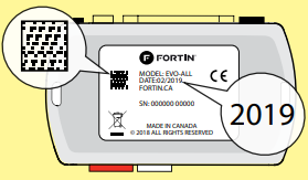
| COMPATIBLE | QR CODE ON THE LABEL |
| MODULE REQUIRED: | MANUFACTURED AFTER: 2019 |
| MODULE | CODE QR SUR ’ÉTIQUETTE |
| COMPATIBLE REQUIS | FABRIQUÉ APRÈS: 2019 |
FIRMWARE VERSION
VERSION LOGICIELLE
58.[06]
MINIMUM
To add the firmware version and the options, use the FLASH LINK UPDATER or FLASH LINK MOBILE tool, sold separately.
 Program bypass option:
IF THE VEHICLE IS NOT EQUIPPED WITH FUNCTIONAL HOOD PIN:
UNIT OPTION
| UNIT OPTION | DESCRIPTION |
| C1 | OEM Remote status (Lock/Unlock) monitoring |
| A11 |
Hood trigger (Output Status). |
NOTES
 *The vehicle must be equipped with 12 inch radio display.
The vehicles OEM remote and SmartKey are still operable during remote start.
**Heated seats
**Rear Defrost The heated seats and rear defrost activate automatically when it’s cold.
***Parking Lights The parking Lights at remote start only.

The vehicle must be equiped with the OEM remote with the door locks.
MANDATORY INSTALL
* HOOD PIN CONTACT DE CAPOT
 HOOD STATUS : THE HOOD PIN SWITCH MUST BE INSTALLED IF THE VEHICLE CAN BE REMOTE STARTED WITH THE HOOD OPEN, SET FUNCTION A11 TO OFF.
A11 ![]()
Notice: the installation of safety elements are mandatory. The hood pin is an essential security element and must be installed.
THIS MODULE MUST BE INSTALLED BY A QUALIFIED TECHNICIAN. A WRONG CONNECTION CAN CAUSE PERMANENT DAMAGE TO THE VEHICLE.
This guide may change without notice. See www.fortin.ca for latest version.
PARTS REQUIRED (NOT INCLUDED)
![]() FLASH LINK UPDATER,
FLASH LINK UPDATER,
![]() FLASH LINK MANAGER
FLASH LINK MANAGER
![]() SOFTWARE | PROGRAMME
SOFTWARE | PROGRAMME
Microsoft Windows Computer with Internet connection
Ordinateur Microsoft Windows avec connection Internet
![]() FLASH LINK MOBILE
FLASH LINK MOBILE
![]() FLASH LINK MOBILE APP
FLASH LINK MOBILE APP
![]() Smartphone AndroId or iOS with Internet connection (provider charges may apply).
Smartphone AndroId or iOS with Internet connection (provider charges may apply).
MANDATORY
HOOD PIN
CONTACT
 REMOTE START SAFETY OVERRIDE SWITCH
 VALET SWITCH COMMUTATEUR VALET
Part #: RSPB available, Sold separately.
Notice: the installation of safety elements are mandatory.
The hood pin and the valet switch are essential security elements and must be installed.
STAND ALONE CONFIGURATION
 Program bypass option
OEM Remote Stand Alone Remote Starter:
 Program bypass option with oem remote:
 Program bypass option with RF KIT antenna:
| UNIT OPTION | DESCRIPTION |
| D1.10 D1.1 |
By default, LOCK, LOCK, LOCK Par défaut, VERROUILLE,VERROUILLE,VERROUILLE |
| C1 | OEM Remote Monitoring |
| H1 to H6 H1 à H6 |
Supported RF Kits and select RF Kit |
REMOTE STARTER FUNCTIONALITY

REMOTE STARTER DIAGNOSTICS
MODULE RED LED
x2 flash :Brake ON
x3 flash :No tach
x4 flash : Ignition before start
x5 flash : Hood Open
REMOTE STARTER WARNING CARD
![]() CUT THIS WARNING CARD AND STICK IT ON A VISIBLE PLACE:
CUT THIS WARNING CARD AND STICK IT ON A VISIBLE PLACE:
or use the package RSPB, Sold separately.
![]() WARNING
WARNING
REMOTE STARTER
THE VEHICLE CAN BE STARTED BY EITHER: PRESSING THE LOCK BUTTON ON THE OEM REMOTE 3 TIMES CONSECUTIVELY OR BY A SMARTPHONE. TURN ON THE SAFETY SWITCH LOCATED UNDER THE DASHBOARD BEFORE WORKING ON THE VEHICLE.
NOTES
![]() THE REMOTE START WILL NOT OPERATE IF :
THE REMOTE START WILL NOT OPERATE IF :

![]() CAUTION
CAUTION
 The remote start is limited to two consecutive command Start or Stop.
 To use the remote again ignition must be turned ON and OFF.
AUTOMATIC TRANSMISSION WIRING CONNECTION

DCRYPTOR PROGRAMMING PROCEDURE
![]() Parts required (not included)
Parts required (not included)
![]() FLASH LINK UPDATER,
FLASH LINK UPDATER,
![]() FLASH LINK MANAGER
FLASH LINK MANAGER
![]() SOFTWARE | PROGRAMME
SOFTWARE | PROGRAMME
Microsoft Windows Computer with Internet connection
Ordinateur Microsoft Windows avec connection Internet
OR
![]()
![]() FLASH LINK MOBILE
FLASH LINK MOBILE
![]() FLASH LINK MOBILE APP
FLASH LINK MOBILE APP
![]() Smartphone Android or iOS with Internet connection
Smartphone Android or iOS with Internet connection
(Internet provider charges may apply)
BEFORE PROGRAMMING SET THE UNIT OPTIONS AND SAVE.

Press and hold
Insert the programming button: the 4-Pin (Data-Link) connector.
The Blue, Red, Yellow and Blue & Red LEDs will alternatively illuminate.

Release the programming button when the LED is BLUE.
If the LED is not solid BLUE disconnect the 4-Pin connector (Data-Link) and go back to step 1.

Insert the required remaining connectors.
 Turn the key to the Ignition ON/RUN position.
![]() The BLUE LED will turn OFF.
The BLUE LED will turn OFF.
![]() The BLUE, YELLOW and
The BLUE, YELLOW and
RED LEDs will alternated.
![]() The RED and YELLOW
The RED and YELLOW
LEDs will alternated.
Make sure that the DELs are flashing RED and YELLOW before continuing programming.


Turn the key to the OFF position.
![]() The RED and YELLOW LEDs alternate.
The RED and YELLOW LEDs alternate.
KEY BYPASS PROGRAMMING PROCEDURE 2/2


![]() The module is now programmed.
The module is now programmed.
OPTIONAL RF-KIT PROGRAMMING
PROGRAM BYPASS OPTION
![]() Program bypass option:
Program bypass option:
H2
☑Supported RF-KITS enable
☑ H2 Fortin 2
![]() The module must be programmed on the vehicle.
The module must be programmed on the vehicle.
 MAKE SURE THE IGNITION KEY HAS BEEN IN THE OFF POSITION FOR AT LEAST 5 SECONDS.

REMOTE STARTER FUNCTIONALITY

All doors must be closed.
 Remote start the vehicle.
 Unlock the doors with the remote-starter remote or the OEM remote.
 Insert and Turn the key to the Ignition ON/RUN position.
 Press the brake pedal.
 The vehicle can now be put in to gear and driven.
![]() Module label
Module label
Notice: Updated Firmware and Installation Guides
Updated fi rmware and installation guides are posted on our web site on a regular basis. We recommend that you update this module to the latest fi rmware and download the latest installation guide(s) prior to the installation of this product.
WARNING
The information on this sheet is provided on an (as is) basis with no representation or warranty of accuracy whatsoever.
It is the sole responsibility of the installer to check and verify any circuit before connecting to it. Only a computer safe logic probe or digital multimeter should be used. FORTIN ELECTRONIC SYSTEMS assumes absolutely no liability or
responsibility whatsoever pertaining to the accuracy or currency of the information supplied. The installation in every case is the sole responsibility of the installer performing the work and FORTIN ELECTRONIC SYSTEMS assumes no liability or responsibility whatsoever resulting from any type of installation, whether performed properly, improperly or any other way. Neither the manufacturer or distributor of this module is responsible of damages of any kind indirectly or directly caused by this module, except for the replacement of this module in case of manufacturing defects. This module must be installed by qualifi ed technician. The information supplied is a guide only. This instruction guide may change without notice. Visit www.fortinbypass.com to get the latest version.
Copyright © 2006-2019, FORTIN AUTO RADIO INC ALL RIGHTS RESERVED PATENT PENDING
![]() TECH SUPPORT
TECH SUPPORT
Tél: 514-255-HELP (4357)
1-877-336-7797
 ADDENDUM GUIDE
www.fortinbypass.com
![]() WEB UPDATE
WEB UPDATE
This guide may change without notice.
See www.fortin.ca for latest version.
Documents / Resources
 |
FORTIN 2023-2024 Vehicle 2 Inch Display Key with Keyless [pdf] Installation Guide EVO-ALL, THAR-FOR5, 117041, 2023-2024 Vehicle 2 Inch Display Key with Keyless, Vehicle 2 Inch Display Key with Keyless, Display Key with Keyless, Key with Keyless, Keyless |