![]() Part number 31149
Part number 31149
Temp. Control Module
Instructions
Wiring Diagram

1a. Connect the motor wires to the control module (Red wire to the “M+” terminal and black wire to the “M-” terminal).
1b. Disconnect the negative battery lead for safety while finishing the wiring. Use the large diameter red (10 AWG) wire to run power directly from the battery positive (+) terminal to the “B” terminal on the control module. Connect the fuse holder in-line with this wire, as shown, but do not insert the fuse yet. Use the yellow female, ring, and butt connectors provided.
1c. Use the large diameter black (10 AWG) wire to run from the negative (-) battery terminal to the “G” terminal on the control module. Use the yellow female connector and ring connector provided.

1d. Use the small diameter red wire (14 AWG) to connect the “+” terminal on the control module to a positive power source.
NOTE: Attaching this wire to an ignition-controlled source will shut off the fan when the engine is turned off. Attach this wire to an uninterrupted (always hot) power source to allow the fan to continue running after the engine is shut off. Use the blue female connector and fuse taps (included) if necessary.
1e. (Optional) For air conditioning control (if desired) connect the “C” terminal on the control module to the positive wire that triggers the A/C compressor using the small diameter green (14 AWG) wire.
Using a voltmeter, determine which wire coming from the compressor is the positive trigger wire. Use the 3-way connector (included) to tap into this wire and send a signal to the fan control module. The fan will cycle on and off with the A/C clutch when the A/C is turned on.
1f. (Optional) For manual switch operation, use Flex-a-lite p/n 31148. Connect the switch as shown on the wiring diagram (previous page). Connect the “M” terminal on the control module to the “1” terminal on the switch. Connect the “2” terminal on the switch to a positive 12v power source. Connect terminal “3” on the switch to a good ground (for switch illumination).
NOTE: To prevent ther-mostatic activation (if only manual switch operation is desired), omit the lead to the “+” terminal of the control box. “B”, “G”, “M+” and “M-” must remain connected. If not using a Flex-alite manual switch, do not connect a ground wire to the switch!
1g. Use the zip ties provided to secure the wires and prevent them from interfering with fan blades, belts, and pulleys in the engine compartment. Reconnect the battery and insert the fuse provided.
Step 2: Insert the temperature probe into the radiator fins
 |
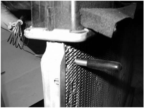 |
| Install temp. probe near inlet hose… | then replace the insulator cap. |
Locate the inlet hose from the engine to the radiator. Remove the black insulator cap and insert the temp. probe through the radiator fins near the inlet hose. Reinstall the black insulator cap.
Step 3: Adjust the temperature control knob on the control box
If you disconnected any hoses or drained coolant to install the fan, reconnect the hoses and refill the radiator. Press the control knob (included in wiring kit) onto the control box shaft. Turn the knob clockwise until it stops. Start the engine and allow it to idle. Using a hand held thermometer (positioned near the inlet hose) or the vehicle’s temperature guage, monitor the temperature. When the coolant temp. is slightly above normal (or desired temp.), turn the knob counter-clockwise just until the fan turns on. From now on, the fan should activate at this temperature setting. Adjust as necessary to maintain desired temperature.
Limited Warranty
This Warranty is provided to the original purchaser only and covers only products purchased by the original purchaser from an authorized Flex-A-Lite distributor. Legend Brands, Inc., 15180 Josh Wilson Rd., Burlington WA 98233, 800-932-3030, warrants to the original purchaser, all Flex-A-Lite products to be free of defects in material and workmanship for a period of one (1) year from the date of purchase. Flex-A-Lite products failing due to manufacturer’s defect within one (1) year from date of purchase, may be returned to the factory through the point of purchase, transportation charges prepaid. If, on inspection, cause of failure is determined to be defective material or workmanship and not by misuse, accident, improper installation, or subsequent installations other than the original vehicle in which it was installed, Legend Brands, Inc., will replace the product free of charge, transportation prepaid. Legend Brands, Inc. will not be liable for incidental, progressive, or consequential damages. Flex-A-Lite warranty is limited to product replacement and will not cover any installation or removal costs should a product qualify for warranty. Some states do not allow the exclusion or limitation of incidental or consequential damages, so the above limitations or exclusions may not apply to you. This warranty gives you specific legal rights and you may also have other rights, which may vary from state to state. Flex-A-Lite is a brand of Legend Brands, Inc.
99842B
Legend Brands, Inc.![]()
Documents / Resources
 |
Flex-a-lite 31149 Temp Control Module [pdf] Instructions 31149, 31148, 31149 Temp Control Module, 31149, Temp Control Module, Control Module, Module |