FIRVENA EO-BAC EnOcean to BACnet MS/TP Gateway

EnOcean to BACnet MS/TP Gateway
Product Information
The EnOcean to BACnet MS/TP Gateway is a device that allows EnOcean devices to communicate with BACnet systems. It is designed to map EnOcean devices to BACnet objects, making it easier to integrate these devices into BACnet systems. The device comes with a user manual that provides detailed instructions on how to use the gateway.
Technical Data
| Parameter | Value |
|---|---|
| Product name | EnOcean to BACnet MS/TP Gateway |
| Product title | EO-BAC |
| Product ID | V1.4 / 2023-01-24 |
| Vendor name | N/A |
| Rated supply voltage | N/A |
| Supply voltage range | N/A |
| Rated input current | N/A |
| Rated input power | N/A |
| Baud rate | N/A |
| Data bits | N/A |
| Stopbits | N/A |
| Parity | N/A |
| Maximum number of devices on the line | N/A |
| Termination | N/A |
| Frequency | N/A |
| Maximum number of handled devices | N/A |
| Repeater device class | N/A |
| Connector | N/A |
| IP Code | N/A |
| Operating temperature | N/A |
| Relative humidity | N/A |
| Dimensions without antenna (mm) | N/A |
| Weight without antenna | N/A |
Product Usage Instructions
To use the EnOcean to BACnet MS/TP Gateway, follow the instructions provided in the user manual. The manual includes the following sections:
- Basic Examples: Provides examples of how to use the gateway in different scenarios.
- RPS Buttons and Switches: Explains how to use RPS buttons and switches with the gateway.
- A5-20-01 HVAC Components, Battery Powered
Actuator: Provides instructions on how to use the A5-20-01 HVAC Components. - D2-01-XX Electronic switches and dimmers with Energy
Measurement and Local Control: Provides instructions on how to use D2-01-XX Electronic switches and dimmers. - BACnet Interface: Describes the BACnet interface and how EnOcean devices are mapped to BACnet objects.
- Configuring the Gateway: Provides brief instructions on how to configure the gateway, especially for connecting EnOcean devices.
- Firmware Update Procedure: Provides instructions on how to update the firmware of the gateway.
Please note that the gateway must be installed by a qualified person (accredited electrician) and in accordance with national and safety standards. Improper installation may cause damage to health, property or the equipment itself.
Terms and Abbreviations
Term/Abbr.: Explanation
- Channel number (CH) …………….Identifier of EnOcean device within the gateway
- COV ……………………………………..Change of Value
- DHCP ……………………………………Dynamic Host Configuration Protocol
- EEP ………………………………………EnOcean Equipment Pofiles
- EURID …………………………………..EnOcean Unique Radio Identifier
- Label ……………………………………User-friendly name of EnOcean device
- IP …………………………………………Internet Protocol
- PoE ………………………………………Power over Ethernet
- MS/TP ………………………………….Master-Slave/Token Passing (data link layer protocol)
- RX ………………………………………..Receive, reception
- Teach-in ……………………………….Pairing of EnOcean devices
- Telegram ………………………………EnOcean message
- TX ………………………………………..Transmit, transmission
- UPnP ……………………………………Universal Plug and Play
- Value index …………………………..Identifier of a data unit within the channel
Introduction
The EO-BAC device is a gateway between EnOcean and BACnet MS/TP communication protocols (Fig. 1.1). EnOcean and BACnet are a set of technologies and communication protocols that are widely used in building automation systems. The EnOcean is a technology that enables the use of wireless and batteryless sensors, switches and actuators. The BACnet is a communication protocol that was designed to provide unified interface for data exchange across a building management system. The EO-BAC gateway can receive data from up to 40 EnOcean devices, store it and provide it through the BACnet MS/TP interface to other devices connected to the BACnet network.
The first part of this manual describes the hardware of the gateway. Chapter 6 describes the BACnet interface and explains how EnOcean devices are mapped to BACnet objects. Chapter 7.3 contains brief instructions for configuring the gateway, especially for connecting EnOcean devices. For firmware update procedure refer to Chapter 8.

Fig. 1.1 Functional overview
Hardware Overview
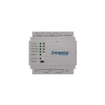
There is a power connector, RS-485 connector, type B USB connector, antenna connector and LED indicators on the front panel (Fig. 2.1). The LEDs indicates the connection of power supply (POWER), traffic in the BACnet network (BAC RX, BAC TX), traffic in the EnOcean wireless network (ENOC), communication through the USB interface (USB) and error states (ERROR). The USB connector is used for configuration and firmware update, it is used by the EO-BAC Tool configuration application. The green POWER and RS-485 connectors are removable, which simplifies device handling if wires are connected.

Fig. 2.1 Gateway overview – front side
There are two switches beside the RS-485 connector that are accessible after pulling out the RS-485 connector (Fig. 2.2).
The left switch sets the USB interface mode:
- the “HID” position (default) allows the EO-BAC Tool application to be connected
- the “MSC” position activates the firmware update mode (see Ch. 8)
The right switch connects a 120-ohm termination resistor to the RS-485 line:
- “OFF” (default): termination resistor disconnected
- “ON”: connected

Fig. 2.2 Gateway overview – meaning of manual switches
Technical Data
Tab. 3.1 Technical data
| Category | Parameter | Value |
|
Product |
Product name | EO-BAC |
| Product title | EnOcean to BACnet MS/TP Gateway | |
| Product ID | 7.1 | |
| Vendor name | FIRVENA s.r.o. | |
|
Electrical data |
Rated supply voltage | 24 V DC |
| Supply voltage range | 10–32 V DC | |
| Rated input current | 50 mA | |
| Rated input power | 1.2 W | |
| RS485 (BACnet MS/TP) |
Baud rate | 9.6, 19.2, 38.4, 57.6, 76.8 or 115.2 kBd |
| Data bits | 8 | |
| Stopbits | 1 | |
| Parity | none | |
| Maximum number of devices on the line | 32 | |
| Termination | Manually activated 120 W resistor | |
| EnOcean | Frequency | 868 MHz |
| Maximum number of handled devices | 40 (max. 20 with SmartACK) | |
| Repeater | ||
| USB | Device class | Custom HID or Mass Storage |
| Connector | Type B | |
|
Operating conditions |
IP Code | IP20 |
| Operating temperature | -20 to +70 °C | |
| Relative humidity | max. 80 % | |
| Dimensions in mm | Dimensions without antenna | Width=126, Height=71, Depth=25 |
| Weight | Weight without antenna | 115 g |
| Box material | ABS, white | |
| EMC | In accordance with the directive | 2014/53/EU, 2011/65/EU RoHS |
| EMC | Approvals tests | ČSN EN 55032, ČSN EN 55035, ČSN EN 6100-4-2, ČSN EN 6100-4-3, ČSN EN 6100-4-4, ČSN EN 6100-4-5, ČSN EN 6100-4-6, ČSN EN 6100-4-11, ČSN EN IEC 6100-6-2 |
Dimensions in mm:

Safety Information and Warnings
Please follow the general safety requirements. This equipment may only be installed by a qualified person (accredited electrician) and after reading these instructions. Improper installation may cause damage to health, property or the equipment itself.
The product meets the general safety requirements. Cover IP 20 allows installation only in normal space.
The gateway must be powered from a safe voltage source that meets the requirements for input voltage range and must be installed in accordance with national and safety standards.
The product may only be used in accordance with this manual.
To avoid a risk of an electrical shock or fire, the maximum of gateway’s operating parameters must not be exceeded.
Use only unmodified products.
It can be used types of cables with sufficient electrical strength for connection.
Storage
Store products at temperature 0-40 °C and relative humidity up to 80 %, and in spaces where condensation on products is eliminated. Products must not be exposed shocks, harmful vapors or gases.
Repairs
Products are repaired by the manufacturer. Products to be repaired are shipped in a package that ensures shock absorption and protects the products against damage during shipment.
Guarantee
The product is warranted 24 months from the date of delivery that is mentioned on the delivery note. The manufacturer guarantees technical and operational products parameters in the range of valid documentation. The warranty period runs from personal goods acceptance by the buyer or from the transport company. Claimed products and written claims for defects are claimed by the manufacturer during warranty period. The complainant shall provide products identification, number of delivery note and defects description. The manufacturer is not responsible for defects caused by improper storage, improper external connection, damages caused by external influences especially due to unacceptable size, incorrect adjustment, improper installation, incorrect operation or normal wear and tear.
Product disposal
The product does not belong to municipal waste. The product must be disposed to the separate waste collection with the possibility of recycling, according to local regulations and legislation. The product contains electronic components.
ROHS Directive
The device is manufactured in accordance with the directive 2015/863/EU (RoHS 3) of the European Parliament and of the Council on the restriction of the use of certain hazardous substances in electrical and electronic equipment.
Power Supply
Power supply from an external source:

Fig. 5.1 Power supply via POWER connector
The gateway must be powered from a safe voltage source that meets the requirements for input voltage range. The electrical installation must be in accordance with national requirements and safety standards.
Configuration
EO-BAC Tool
This chapter is a brief guide to the use of the EO-BAC Tool application.
The application EO-BAC Tool is used to configure the gateway. The main purpose of the application is to manage EnOcean devices connected to the gateway. The application is also a useful verification tool whereby you can evaluate whether your system works well. It allows to see the states, measured quantities, communication intervals or signal strength of the connected EnOcean devices. The application also allows setting BACnet configuration parameters such as MSTP address, baud rate, etc.
Communication between the application and the gateway is via USB interface. There is no need to install a driver, just connect the gateway to your computer using an appropriate USB cable and run the application. The application automatically connects to the first detected gateway.
Main window overview
- Communication control – basic control of communication with the gateway.
- Application status – shows the state that the application is currently in.
- Gateway – an editor of gateway configuration.
- Teach-in telegram – the last teach-in telegram received by the connected gateway.
- Channel configuration – an editor of the selected Rx channel.

Fig. 6.1 Main window overview
Assigning EnOcean elements – unidirectional
This teach-in procedure is only applicable for unidirectional communication when the gateway only receives data.
Let’s have a CO2 sensor (A5-09-04) we want to assign to the channel 35. The procedure is as follows (see Fig. 6.2):
- Push the pairing button to transmit a teach-in telegram.
- The received telegram is displayed in the “Channel” panel.
- Select the channel number 35.
- Click “Save” to confirm changes.
- Now the sensor is assigned to channel 35 and its data is available through the BACNet interface.

Fig. 6.2 Adding elements – teach-in procedure
Optionally, the Label can be set for the device. The Label is used in the Description property of the objects MSV 199–4099. If the Label field is left empty, the default text will be used.
The knowledge of EEP allows the gateway to interpret the received data correctly. Some types of EnOcean devices do not provide the EEP information in their teach-in telegram or even not have a special telegram for teach-in (e.g. buttons and switches). In that case, the EEP must be set manually, it is usually given by a label on the device or a datasheet.
Devices can also by assigned manually by entering the ID and EEP – Fig. 6.3.

Fig. 6.3 Adding elements – manually
Assigning EnOcean elements – bidirectional
This teach-in procedure is applicable for EnOcean devices with bidirectional communication profiles when the gateway is supposed to receive data from the device and also transmit data to the assigned device.
Let’s have a valve actuator (A5-20-01) we want to assign to the channel 35. The procedure is as follows (see Fig. 6.4):
- Select the channel number 35.
- Check the “LRN enable”
Channel 35 is now in the teach-in mode. - Push the pairing button to transmit a teach-in telegram from the actuator.
- Gateway receives the telegram and sends a teach-in response.
- The device is automatically saved to the selected channel and its data is available through the BACNet interface.
To change the Label, enter the new text and click “Save”.

Fig. 6.4 Adding elements – bidirectional teach-in procedure
Assigning Smart ACK devices
To assign a Smart ACK device to the gateway, the procedure is the same as for bidirectional profiles (6.1.3). Repeaters are not supported, there must be a direct connection between the gateway and the Smart ACK device.
Definition of Virtual Device
The gateway can be used to simulate a real EnOcean device. This function is necessary when controlling actuators that do not implement any bidirectional profile, typically some types of relay switches.
For example, we want to control a relay switch that supports reception of a Door/Window Contact D5-00-01. The procedure is as follows.
First, define a virtual device of type D5-00-01, for example at channel 35 (see Fig. 6.5):
- Select a channel (channel 35)
- Check “Simulate device”
- Select the type of device (D5-00-01)
- Click “Save” to confirm changes
- The device is saved to the selected channel and its data is available through the BACnet interface.
Second, pair the virtual device with the relay switch:
- Select the channel 35 (Fig. 6.6)
- Put the relay switch to the pairing mode (follow the procedure given by the manufacturer of the switch)
- Click on the “Send LRN” button
- The gateway will transmit a teach-in telegram of the virtual device
- The switch will receive the teach-in telegram and save the virtual device
Notes:
- Each virtual device must have a unique ID, this is given by the MyID setting.
- To enable receiving the actual state of the switch, assign it to a different channel.

Fig. 6.5 Adding elements – virtual device

Fig. 6.6 Virtual device – send teach-in telegram
Removing EnOcean elements
- Select a channel
- Click the “Delete” button or press the Delete key
To remove all elements, select all channels (Ctrl+A) and use Delete.
Backup and Restore
The configuration of the gateway can be exported to a file for later recovery or reuse. To back up the configuration:
- Connect the gateway and let the configuration to be loaded.
- Use the Save command [Ctrl+S] or [File > Save].
- Define the file path and name in the dialog shown.
- Confirm “Save”.
To restore the configuration:
- Connect the gateway and check if the communication works properly.
- Use the Open command [Ctrl+O] or [File > Open].
- Select a file and confirm “Open” in the dialog shown.
- A prompt dialog appears, select “Yes” to confirm the gateway configuration is to be overwritten.
Notes:
- If you select “No”, the file opens in a new window where you can edit it or copy individual channels to the connected gateway.
- Only channels are restored, the “Gateway Settings” are preserved.
BACnet Interface
Mapping of EnOcean Devices
EnOcean devices are mapped as a set of standard BACnet objects. The gateway can handle up to 40 EnOcean devices. To assign an EnOcean device, the teach-in procedure has to be carried out (see Ch. 6.1). The assigned EnOcean devices are identified by Channel (CH1…40) within the gateway, the Channel is selected by user during teach-in procedure.
Data fields received in a telegram are divided into individual standard BACnet objects so that they can be accessed from the BACnet network – see Fig. 7.1. The gateway contains a database of supported EnOcean products, objects are created depending on the type of EnOcean device (EEP) that is assigned to the channel during teach-in procedure.

Fig. 7.1 Conversion of data
Three types of data fields are distinguished:
- Numeric value: usually a measured physical quantity such as temperature, humidity, etc.
- Enumeration: defined as a list of items that express a state or configuration of the device
- Boolean: two-state enumeration whose items can be interpreted as true/false, such as on/off, enabled/disabled, open/closed, etc.
In addition, two directions are distinguished:
- RX: data received by the gateway (incoming telegrams)
- TX: data transmitted by the gateway (outgoing telegrams)
The data fields are stored internally as Values. The Values are identified by Value index, 100 Values is reserved per channel (indexes 0 to 99) – see Fig. 7.2 and Fig. 7.3.
The Values from Telegram data range represent a model of EnOcean telegram. For simple devices (such as sensors with unidirectional communication) the model of telegram can also be assumed to be a model of EnOcean device. Some more complex EEP definitions consist of several types of telegrams that represent different commands, so the device cannot be described by a single telegram. Special mapping is created for these devices.
For direction “RX”, all used Values are mapped to Analog Input (AI) objects. For direction “TX” all used Values are mapped to Analog output (AO) objects.
The mapped data fields from EnOcean telegram are indexed in the same order as they appear in the EEP definition – see [3].
Besides the data values, there are also helper values for each channel that provide status information – see Tab. 7.1. If the channel is not occupied the associated BACnet objects are hidden.
Tab. 7.1 Helper values
| Index | Name | Meaning | Value Range |
| 90 | Telegram counter | Number of received/sent telegrams | 0…65535 (overflows to zero) |
| 91 | Telegram age | Time elapsed since the last telegram | 0…65000 s (65535: no telegram, 65001: range exceeded) |
The object Instance_Number (part of Object_Identifier property) is composed of the Channel number and Value index. Hundreds contain the Channel number of EnOcean device (Channel 1…40) that the BACnet object belongs to. Units contain the Value index that identifies a data field (Value 0…99) – see Fig. 7.4.
Examples of mapping for individual EnOcean devices can be found in ANNEX A.

Fig. 7.2 Values
| AI | ||||
| CH1 | Value 0 | 100 | Temperature |
A5-02-05 |
| Value 1 | 101 | |||
| Value 2 | 102 | |||
| Value 3 | 103 | |||
| Value 4 | 104 | |||
| … | … | … | ||
| Value 90 | 190 | T. Counter | ||
| Value 91 | 191 | T. Age | ||
| CH2 | Value 0 | 200 | Humidity | A5-09-04 Gas Sensor, CO2 Sensor  |
| Value 1 | 201 | Concentration | ||
| Value 2 | 202 | Temperature | ||
| Value 3 | 203 | H-Sensor | ||
| Value 4 | 204 | T-Sensor | ||
| … | … | … | ||
| Value 90 | 290 | T. Counter | ||
| Value 91 | 291 | T. Age | ||
| CH40 | Value 0 | 4000 | Power Fail | D2-32-02 A.C. Current Clamp, 3 channels  |
| Value 1 | 4001 | Divisor | ||
| Value 2 | 4002 | Channel 1 | ||
| Value 3 | 4003 | Channel 2 | ||
| Value 4 | 4004 | Channel 3 | ||
| … | … | … | ||
| Value 90 | 4090 | T. Counter | ||
| Value 91 | 4091 | T. Age | ||

Fig. 7.3 Mapping of EnOcean devices

Fig. 7.4 Numbering of objects
Supported Object Types
This section describes object types that may be present in the device. Lists of optional and proprietary properties are provided for each object type. Information on range restrictions and default values of properties can be found here too. Writable properties are marked in the “W” column.
Device
There is one instance of the Device object in the gateway. It represents the gateway itself.
Tab. 7.2 Device object – properties
| Property Name | Value Range | Default | W |
| Required | |||
| Object_Identifier | (device, 1001) | ||
| Object_Name | 1…126 bytes | EO-BAC_{Instance_Number} | 1) |
| Object_Type | device | ||
| System_Status | |||
| Vendor_Name | |||
| Vendor_Identifier | |||
| Model_Name | |||
| Firmware_Revision | |||
| Application_Software_Version | |||
| Protocol_Version | |||
| Protocol_Revision | |||
| Protocol_Services_Supported | |||
| Protocol_Object_Types_Supported | |||
| Object_List | |||
| Max_APDU_Length_Accepted | |||
| Segmentation_Supported | |||
| APDU_Timeout | 0…65535 ms | 6000 ms | |
| Number_Of_APDU_Retries | 0…255 | 3 | |
| Device_Address_Binding | |||
| Database_Revision | |||
| Property_List | |||
| Optional | |||
| Location | 0…126 bytes | unknown | 1) |
| Description | 0…126 bytes | Gateway EnOcean/BACnet-MSTP | 1) |
| Max_Master | 0…127 | 127 | |
| Max_Info_Frames | 1…255 | 1 | |
| Proprietary | |||
| Offset_ID | 0…4 194 175 | 1000 | 2) |
| MSTP_Address | 0…127 | 1 | 2) |
| MSTP_Baudrate | 38400 Bd | ||
| LED_Indication | ENABLED |
- After entering “!default”, the default text is restored.
- Instance_Number Offset_ID + MSTP_Address, example: 1000 2 (device, 1002)
Analog Input (AI)
The number of these objects depends on the number of assigned EnOcean devices and their type.
Tab. 7.3 Analog input object – properties
| Property Name | Value Range | Default | W |
| Required | |||
| Object_Identifier | |||
| Object_Name | see below | ||
| Object_Type | |||
| Present_Value | 1) | ||
| Status_Flags | |||
| Event_State | |||
| Out_Of_Service | False | ||
| Units | |||
| Property_List | |||
| Optional | |||
| Description | 0…126 bytes | see below | |
| Reliability | |||
| Min_Pres_Value | |||
| Max_Pres_Value | |||
| COV_Increment | 0…65535 | 65535 (Off) | 2) |
| Proprietary | |||
- Present_Value writable if Out_Of_Service = true.
- Value 65535 turns off the COV reporting for the object.
AI 100–4099: Objects from this range are mapped to RX Values (see 7.1). AI 100–199 belongs to Channel 1, AI 200–299 to Channel 2, etc. Objects are not created for unused Values.
Object_Name = “RX_CH{ChNum}_V{ValueIndex}_{ValueName}”
(e.g. RX_CH1_V0_Temperature)
Description = “{ValueName} {ValueRange}” (e.g. Temperature 0…40 °C)
Analog Output (AO)
The number of these objects depends on the number of assigned EnOcean devices and their type.
Tab. 7.4 Analog output object – properties
| Property Name | Value Range | Default | W |
| Required | |||
| Object_Identifier | |||
| Object_Name | see below | ||
| Object_Type | |||
| Present_Value | |
||
| Status_Flags | |||
| Event_State | |||
| Out_Of_Service | False | |
|
| Units | |||
| Priority_Array | |||
| Relinquish_Default | |
||
| Property_List | |||
| Current_Command_Priority | |||
| Optional | |||
| Description | 0…126 bytes | see below | |
| Min_Pres_Value | |||
| Max_Pres_Value | |||
| Proprietary | |||
AO 100100–104099: Objects from this range are mapped to TX Values (see 7.1). AO 100100–100199 belongs to Channel 1, AI 100200–100299 to Channel 2, etc. Objects are not created for unused Values.
Object_Name = “TX_CH{ChNum}_V{ValueIndex}_{ValueName}” (e.g. TX_CH1_V0_Valve position)
Description = “{ValueName} {ValueRange}” (e.g. Valve position 0…100 %)
Multistate Value (MSV)
There are several MSV objects representing settings and states of the gateway and channels.
Tab. 7.5 Multistate value object – properties
| Property Name | Value Range | Default | W |
| Required | |||
| Object_Identifier | |||
| Object_Name | see below | ||
| Object_Type | |||
| Present_Value | |
||
| Status_Flags | |||
| Event_State | |||
| Out_Of_Service | False | |
|
| Number_Of_States | |||
| Property_List | |||
| Optional | |||
| Description | 0…126 bytes | see below | |
| State_Text | |||
| Proprietary | |||
- Writable only for Value Index 99 (MSV 199, 299, …, 4099). After entering “!default”, the default text is restored.
Tab. 7.6 List of MSV objects
| Ch. | Device | Object ID | Object Name | Descriptiton | W |
| – |  |
MSV 1 | UCOV_MODE | Broadcast mode for unsubscribed COV reporting | |
| MSV 2 | REPEATER_MODE | EnOcean repeater setting | |
||
| 1…40 | RX | MSV 199, 299, …, 4099 |
CH{ChNum}_CONFIG | {EEP} {Title} ({SenderID}) |
|
| 1…40 |
TX |
MSV 100195, 100295, …, 104095 |
TX_CH{ChNum}_SEND | Send option for Device{ChNum} |
|
MSV 1–2: These objects represent setting parameters of the gateway.
MSV 1 (UCOV_MODE): This parameter configures the function of Unsubscribed Change of Value (UCOV) reporting for all AI objects that have COV reporting enabled (COV_Increment < 65535). When turned on, the gateway sends a broadcast COV report (UnconfirmedCOVNotification message) if the condition specified by COV_Increment property is met.
| Value | Meaning |
| 1 – OFF (default) | Turned off |
| 2 – LOCAL | Turned on for local network reporting |
| 3 – GLOBAL | Turned on for global network reporting |
MSV 2 (REPEATER_MODE): This parameter configures the function of EnOcean repeater. If turned on, the gateway forwards received telegrams in the EnOcean network.
| Value | Meaning |
| 1 – OFF (default) | Off |
| 2 – LEVEL1 | Level 1 (only original telegrams) |
| 3 – LEVEL2 | Level 2 (original and once repeated telegrams) |

Fig. 7.5 Repeater function
MSV 199, 299, …, 4099 (CONFIG): There are 40 MSV objects (one for each channel) that indicate the state of the channel.
| Value | Meaning |
| 1 – FREE (default) | The channel is not configured, no device is assigned. |
| 2 – ASSIGNED | The channel is configured, a device is assigned. |
MSV 100195, 100295, …, 104095 (SEND): There are up to 40 of these objects (one for each channel), they are mapped to TX Value 95. It serves to control transmitting of data from the gateway to the device. Objects are created only for used channels.
| Value |
| 1 – None (default) |
| 2 – SendNow |
| 3 – OnReceived |
| 4…10 |
| 11 – OnWriteV0 |
| … |
| 25 – OnWriteV14 |
| 26 – OnWriteAny |
Proprietary properties
Tab. 7.7 Proprietary properties
| Property Name | Property ID | Datatype | Value Range | Object Type | Meaning | |
| Offset_ID | 1000 | Unsigned | 0…4 194 175 (0x3F FF7F) | Device | Used to modify the Object_Identifier | |
| MSTP_Address | 1001 | Unsigned | 0…127 | Device | MAC address of the gateway | |
| MSTP_Baudrate | 1002 | Unsigned | 1:9600 Bd 2:19200 3:38400 |
4:57600 5:76800 6:115200 |
Device | Communication speed of the MS/TP interface |
| LED_Indication | 1100 | Unsigned | 0:DISABLED 1:ENABLED |
Device | Allows to deactivate the LED indicators on the front panel | |
Firmware Update
The firmware is constantly being improved and extended to support new features and EnOcean devices. The actual version of the firmware is available for download on the FIRVENA website.
The number of firmware version can be determined using the EO-BAC Tool:

To update firmware in the gateway:
- Unplug the RS485 connector
- Set the left switch to the “MSC” position
- Connect the gateway to a computer using a USB cable with type B connector
- The device appears as an external disk, copy a new firmware file to the disk

- Set the left switch back to the “HID” position, the gateway reboots
- Now, the gateway checks the file and overwrites the current firmware with the new one
- The result is indicated by LEDs
- Disconnect the USB cable and plug the RS485 connector back

References
- EnOcean Technical Specifications (https://www.enocean-alliance.org/specifications/)
- EnOcean Equipment Profiles (EEP)
(https://www.enocean-alliance.org/wp-content/uploads/2020/07/EnOcean-Equipment-Profiles-3-1.pdf) - Communication telegrams defined in EnOcean equipment profiles
(http://tools.enocean-alliance.org/EEPViewer/) - Smart Acknowledge – Bidirectional communication with energy harvesting devices
(https://www.enocean-alliance.org/wp-content/uploads/2020/04/SmartAcknowledge_Specification_v1.7.pdf) - EnOcean Unique Radio Identifier – EURID Specification
(https://www.enocean-alliance.org/wp-content/uploads/2021/03/EURID-v1.2.pdf) - Yabe (BACnet Explorer) (https://sourceforge.net/projects/yetanotherbacnetexplorer/)
Revision History
| Date | Version | Description |
| 2022-04-01 | V1.0 | Initial release |
| 2022-08-05 | V1.1 | Added bidirectional communication |
| 2022-11-01 | V1.2 | Added Ch. 6.1.5 Updated figures Updated ANNEX A |
| 2022-12-14 | V1.3 | Chapters rearranged Added Ch 4, 5 |
| 2022-01-23 | V1.4 | Extended ANNEX A (D2-01-XX) |
ANNEX A Mapping examples of EnOcean devices
A.1 Basic Examples
MSV 199, 299, …, 4099:
| Ch. | Device | Object ID | Object Name | Description | Value |
| 1 |  |
MSV 199 | CH1_CONFIG | A5-02-05 Temperature Sensors, Temperature Sensor Range 0°C to +40°C (01-81-28-68) | ASSIGNED |
| 2 | MSV 299 | CH2_CONFIG | 00-00-00 None (FF-FF-FF-FF) | FREE | |
| … | |||||
| 32 |  |
MSV 3299 | CH32_CONFIG | D5-00-01 Contacts and Switches, Single Input Contact (01-C1-2E-70) | ASSIGNED |
| … | |||||
| 39 | MSV 3999 | CH39_CONFIG | 00-00-00 None (FF-FF-FF-FF) | FREE | |
| 40 |  |
MSV 4099 | CH40_CONFIG | A5-09-04 CO2 Sensor (01-85-BA-3E) | ASSIGNED |
AI 100–4099:
| Ch. | Device | Object ID | Object Name | Description | Present Value | Unit |
| 1 | A5-02-05 |
AI 100 | CH1_V0_Temperature | Temperature 0…40 °C | 22.4 | °C |
| AI 190 | CH1_V90_Telegram counter | Number of received telegrams 0…65535 | 12 | – | ||
| AI 191 | CH1_V91_Telegram age | Time elapsed since the last telegram 0…65000 s | 252 | s | ||
| 2 | 00-00-00 | |||||
| … | ||||||
| 32 |
D5-00-01 |
AI 3200 | CH32_V0_Contact | Contact 0:open, 1:closed | 1 | – |
| AI 3290 | CH32_V90_Telegram counter | Number of received telegrams 0…65535 | 50 | – | ||
| AI 3291 | CH32_V91_Telegram age | Time elapsed since the last telegram 0…65000 s | 10 | s | ||
| … | ||||||
| 39 | 00-00-00 | |||||
| 40 | A5-09-04 |
AI 4000 | CH40_0_Humidity | Humidity 0…100 % | 45 | % |
| AI 4001 | CH40_1_Concentration | Concentration 0…2550 ppm | 1451 | ppm | ||
| AI 4002 | CH40_2_Temperature | Temperature 0…51 °C | 23.2 | °C | ||
| AI 4090 | CH40_V90_Telegram counter | Number of received telegrams 0…65535 | 2 | – | ||
| AI 4091 | CH40_V91_Telegram age | Time elapsed since the last telegram 0…65000 s | 33 | s |
RPS Buttons and Switches
The following example applies to F6-02-01, F6-02-02, F6-02-03 and F6-02-04
| Ch. | Device | Object ID | Object Name | Description | Present Value | Unit |
| 1 | F6-02-02 |
AI 100 | CH1_V0_BI | BI 0:released, 1:pressed | 1 | – |
| AI 101 | CH1_V1_B0 | B0 0:released, 1:pressed | 0 | – | ||
| AI 102 | CH1_V2_AI | AI 0:released, 1:pressed | 0 | – | ||
| AI 103 | CH1_V3_A0 | A0 0:released, 1:pressed | 0 | – | ||
| AI 104 | CH1_V4_Rocker B | -1:null, 0:off, 1:on | 1 | – | ||
| AI 105 | CH1_V4_Rocker A | -1:null, 0:off, 1:on | 0 | – | ||
| AI 190 | CH1_V90_Telegram counter | Number of received telegrams 0…65535 | 12 | – | ||
| AI 191 | CH1_V91_Telegram age | Time elapsed since the last telegram 0…65000 s | 1 | s | ||
| 2 | 00-00-00 | |||||
| … |
V4 and V5 remember the rocker state for channel A and B, this is out of the EEP definition. Rocker B goes 1:on when BI was pressed, Rocker B goes 0:off when B0 was pressed. When no telegram has been received yet, rocker has the initial value -1:null.
A5-20-01 HVAC Components, Battery Powered Actuator
The actuator wakes up periodically, transmits the actual value and waits for a response with a new setpoint, which must be sent within 1 second. The response is built from Present_Value properties of TX data objects. The response also contains other settings, e.g. Set point type selection, Set point inverse, Summer mode, Service mode. Not all objects are listed in the table, max. number of data values is 10.
Direction RX (from actuator):
| Ch. | Device | Object ID | Object Name | Description | Present Value | Unit |
| 1 | A5-20-01 |
AI 100 | RX_CH1_V0_Current Value | Current Value 0…100 % | 25 | % |
| … | Values according to the EEP spec. and visibility setting | |||||
| AI 109 | ||||||
| AI 190 | RX_CH1_V90_Telegram counter | Number of received telegrams 0…65535 | 155 | – | ||
| AI 191 | RX_CH1_V91_Telegram age | Time elapsed since the last telegram 0…65000 s | 231 | s | ||
| MSV 199 | CH1_CONFIG | A5-20-01 HVAC Components, Battery Powered Actuator (01- 89-6C-98) |
2 |
– |
||
| 2 | 00-00-00 | |||||
| … | ||||||
Direction TX (to actuator):
| Ch. | Device | Object ID | Object Name | Description | Present Value | Unit |
| 1 | A5-20-01 | AO 100100 | TX_CH1_V0_Valve position or Temperature Setpoint | Valve position or Temperature Setpoint 0…100 % | 25 | % |
| … | Values according to the EEP spec. and visibility setting | |||||
| AO 100109 | ||||||
| MSV 100195 | TX_CH1_SEND | Send option for Device1 | 3 (OnReceive) | – | ||
| 2 | 00-00-00 | |||||
| … | ||||||
D2-01-XX Electronic switches and dimmers with Energy Measurement and Local Control
Device types from the D2-01-XX group share the same telegram definitions – see the profile D2-01-00 (http://tools.enocean-alliance.org/EEPViewer/profiles/D2/01/00/D2-01-00.pdf). There are several messages distinguished by the Command ID data field. Each type supports only certain commands and functions, e.g. type 0x02 has one dimmable output, type 0x12 has two relay outputs without dimming function or type 0x0B supports energy and power measurements.
The gateway creates a universal interface for all device types from the D2-01-XX group, regardless of the features supported by a particular type.
Example with NodOn Micro Smart Plug (D2-01-0E) – Measurements
This actuator has one output channel and supports energy and power measurements.
Incoming data
Objects AI101…106 contains data from the status message CMD 4, objects 107…110 from the measurement message CMD 7. The object AI100 indicates which CMD was received last.

The most important is CMD4 -> Output value, which indicates the ON/OFF state of the actuator. Outgoing data
It is possible to transmit different commands. A constant number of objects is created, the number is given by the message utilizing the maximum number of objects. The command is switched by the Command ID value, which is always at the first position (AO100100). The meaning of the objects from AO100101 up depends on the Command ID. The default command is CMD1. 
The most important is CMD 1, which is used to switch ON/OFF the output (0% => OFF; 100% => ON). The Output value in percent and Dim value is only applicable to devices with the dimming feature supported. The value 127% corresponds to 0x7F: Output value not valid / not applicable.
Setting up the measurement through BACnet interface
- Set Command ID (AO100100) to CMD 5 – Set Measurement
- The meaning of objects is as follows:

- Enter inputs, there are several parameters according to the EEP specification.
- Write SEND = 2:SendNow to transmit the telegram to the actuator.
The type D2-01-0E supports measurement report on query (CMD 6) or automatic reporting based on the configuration sent in the CMD 5.
The power and energy measurements are configured and reported separately, determined by CMD 5 -> Measurement mode and Unit; CMD 4 -> Unit.
The measured value is 4 byte in size, split into two 16-bit values (Measurement value = 256 * MSB + LSB), the physical unit is indicated by the Unit value.
Example with NodOn Relay Switch (D2-01-12) – Controlling the output
This actuator has two output channels, the example shows switching ON of the second channel. TX data are first prepared by writing into the TX data objects, then the control telegram (CMD1 – Set output) is sent by writing Send option = 2:SendNow. The actuator returns a status message (CMD4 – Status response), the message says the channel 2 (numbered from zero) is ON.
The Send option can also be configured so that the gateway sends when Output value is written (Send option = 13:OnWriteV2).
Dim value is not supported by this type and is ignored.
Direction TX (to actuator):
| Ch. | Device | Object ID | Object Name | Description | Present Value | Unit |
| 1 | D2-01-12 | AO 100100 | TX_CH1_V0_Command ID | 1:Set Output;2:Set Local; … | 1 | – |
| AO 100101 | TX_CH1_V1_I/O channel | 0…31 | 1 | – | ||
| AO 100102 | TX_CH1_V2_Output value | 0…127 % | 100 | % | ||
| AO 100103 | TX_CH1_V3_Dim value | 0:Switch to output value;1:Dim to output value – timer 1; … | 0 | – | ||
| MSV 100195 | TX_CH1_SEND | Send option for Device1 | 2 (SendNow) | – | ||
| 2 | 00-00-00 | |||||
| … |
Direction RX (from actuator):
| Ch. | Device | Object ID | Object Name | Description | Present Value | Unit |
| 1 | D2-01-12
|
AI 100 | RX_CH1_V0_Command ID | 4:Status Response; 7:Measurement Response; | 4 | – |
| AI 101 | RX_CH1_V1_I/O channel | 0…31 | 1 | – | ||
| AI 102 | RX_CH1_V2_Output value | 0…127 % | 100 | % | ||
| … | Other objects | |||||
| AI 190 | RX_CH1_V90_Telegram counter | Number of received telegrams 0…65535 | 45 | – | ||
| AI 191 | RX_CH1_V91_Telegram age | Time elapsed since the last telegram 0…65000 s | 4563 | s | ||
| MSV 199 | CH1_CONFIG | D2-01-12 Electronic switches and dimmers with Energy Measurement and Local Control, Type 0x12 (05-84-2C-D0) |
2 |
– |
||
| 2 | 00-00-00 | |||||
| … | ||||||
D2-11-XX Bidirectional Room Operating Panel (Smart ACK)
What is Smart ACK?
EnOcean sensors are in sleep mode most of the time to reduce power consumption, so they cannot receive any telegram. The Smart ACK protocol enables bidirectional communication with energy self-sufficient devices. For example, Room Operating Panels D2-11-XX utilize the Smart ACK communication to receive data, which is used to show symbols on the display or override some parameters.
The Smart ACK protocol is described in [4]. When a message is sent to a Smart ACK Sensor, a device called “Post Master” stores it in a “Mailbox” until the sensor is ready to receive telegrams. When the sensor wakes up, it checks the Mailbox. The Post Master sends the message buffered in the Mailbox or Mailbox Empty message if the Mailbox is empty. The sensor receives the response from Post Master and returns to sleep mode. The Mailbox is established in Post Master during teach-in process.
The gateway does not support repeaters, there must be a direct connection between the gateway and the Smart ACK device, i.e. Post Master and Mailbox are located in the gateway.
Example with Thermokon SR06 LCD (D2-11-07)
Direction RX (from sensor):
The sensor sends two types of messages, ID 0 or ID 2. When Message ID is 0, only Set Point Type is valid, other values should be ignored.
Communication is initiated by the sensor on heartbeat (default 1000 s), change of measured value or button press (parameter change), which is indicated by TelegramType.
| Ch. | Device | Object ID | Object Name | Description | Present Value | Unit |
| 1 | D2-11-07
|
AI 100 | Set Setpoint type | 0:Temperature correction;1:Temperature setpoint | 1 | – |
| AI 101 | Telegram Type | 0:Heartbeat;1:Change of temperature or humidity value;2:User caused parameter change | 2 | – | ||
| AI 102 | Message ID | 0:ID-0;2:ID-2 | 2 | – | ||
| AI 103 | Temperature | 0…40 °C | 23.84 | °C | ||
| AI 104 | Humidity | 0…100 % | 0 | % | ||
| AI 105 | Setpoint offset | 0…255 | 170 | – | ||
| AI 106 | Basesetpoint | 15…30 °C | 21 | °C | ||
| AI 107 | Valid temperature correction | 1:-1…1K;2:-2…2K;3:-3…3K;4:- 4…4K;5:-5…5K;6:-6…6K;7:- 7…7K;8:-8…8K;9:-9…9K;10:- 10…10K |
3 |
– |
||
| AI 108 | Fan speed | 0:Auto;1:Speed 0;2:Speed 1;3:Speed 2;4:Speed 3;7:Not available |
7 |
– |
||
| AI 109 | Occupancy state | 0:State Unoccupied;1:State Occupied | 0 | – | ||
| … | ||||||
| 2 | 00-00-00 |

Direction TX (to sensor):
The gateway responds with message ID 1. Settings are changed by writing these values and SendOption = 2:SendNow, changes will apply next time the sensor wakes up. Without a response, the sensor uses the last settings.
SetPointType, TemperatureCorrection, BaseSetpoint and ValidTemperatureCorrection must be mirrored from RX data if no change is required.
| Ch. | Device | Object ID | Object Name | Description | Present Value | Unit |
| AO 100100 | Set Setpoint type | 0:Temperature correction;1:Temperature setpoint | 1 | – | ||
| AO 100101 | Display heating symbol | 0:Heating symbol off;1:Heating symbol on | 0 | – | ||
| AO 100102 | Display cooling symbol | 0:Cooling symbol off;1:Cooling symbol on | 0 | – | ||
| AO 100103 | Display window open symbol | 0:Window open symbol off;1:Window open symbol on | 1 | – | ||
| AO 100104 | Message ID | 1:ID-1 | 1 | – | ||
| AO 100105 | Temperature correction | 0…255 | 128 | – | ||
| 1 | D2-11-07 | AO 100106 | Basesetpoint | 15…30 °C | 21 | °C |
| 1:-1…1K;2:-2…2K;3:-3…3K;4:- | ||||||
| AO 100107 |
Valid temperature correction |
4…4K;5:-5…5K;6:-6…6K;7:- 7…7K;8:-8…8K;9:-9…9K;10:- |
3 | – | ||
| 10…10K | ||||||
| AO 100108 |
Fan speed |
0:Auto;1:Speed 0;2:Speed 1;3:Speed 2;4:Speed 3;7:Not available |
0 |
– |
||
| AO 100109 | Occupancy state | 0:State Unoccupied;1:State Occupied | 0 | – | ||
| MSV 100195 | TX_CH1_SEND | Send option for Device10 | 2 (SendNow) | – | ||
| 2 | 00-00-00 | |||||
| … |
D2-15-00 People Activity Sensor
| Ch. | Device | Object ID | Object Name | Description | Present Value | Unit |
| 1 | D2-15-00 |
AI 100 |
CH1_V0_Presence |
0:Present;1:Not Present;2:Not detectable;3:Presence Detector error |
0 |
– |
| AI 101 | CH1_V1_Energy Storage Status | 0:High;1:Medium;2:Low;3:Critical | 0 | – | ||
| AI 102 | CH1_V2_Pir Update Rate | 1…16 s | 1 | s | ||
| AI 103 | CH1_V3_Pir Counter | 0…65535 | 7568 | – | ||
| AI 104 | CH1_V4_Activity | 0…100 % | 52 | % | ||
| AI 190 | CH1_V90_Telegram counter | Number of received telegrams 0…65535 | 6 | – | ||
| AI 191 | CH1_V91_Telegram age | Time elapsed since the last telegram 0…65000 s | 11 | s | ||
| MSV 199 | CH1_CONFIG | D2-15-00 People Activity Sensor (00-31-C2-2F) | 2 | – | ||
| 2 | 00-00-00 | |||||
| … |
The Activity is computed by gateway based on two subsequent values of the Pir Counter. When the Pir Update Rate is 1s and the sensor transmits data every 2 minutes, 100% corresponds to the Pir Counter increment of 120.

ANNEX B BACnet Protocol Implementation Conformance Statement (PICS)
- Date: March 28, 2022
- Vendor Name: FIRVENA s.r.o.
- Product Name: EO-BAC
- Product Model Number: EO-BAC
- Application Software Version: V1.0
- Firmware Revision: V1.0
- BACnet Protocol Revision: 14
Product Description:
The EO-BAC device is a gateway between EnOcean and BACnet MS/TP communication protocols. It receives data from EnOcean sensors and provides it to other devices connected to the BACnet network.
BACnet Standardized Device Profiles Supported:
- BACnet Gateway (B-GW)
BACnet Interoperability Building Blocks Supported:
- Data Sharing-ReadProperty-B (DS-RP-B)
- Data Sharing-ReadPropertyMultiple-B (DS-RPM-B)
- Data Sharing-WriteProperty-B (DS-WP-B)
- Data Sharing-WritePropertyMultiple-B (DS-WPM-B)
- Data Sharing-Change Of Value Unsubscribed-B (DS-COVU-B)
- Device Management-Dynamic Device Binding-B (DM-DDB-B)
- Device Management-Dynamic Object Binding-B (DM-DOB-B)
- Device Management-DeviceCommunicationControl-B (DM-DCC-B)
- Gateway-Embedded Objects-B (GW-EO-B)
Segmentation Capability: No segmentation
Standard Object Types Supported:
- Refer to user manual
- BACnet Data Link Layer Options: MS/TP master
- Baud rates: 9600, 19200, 38400, 57600, 76800, 115200 Bd
- Device Address Binding: No
- Networking Options: None
- Character Sets Supported: ISO 10646 (UTF-8)
- Gateway Options:
- Refer to user manual
Documents / Resources
 |
FIRVENA EO-BAC EnOcean to BACnet MS/TP Gateway [pdf] User Manual EO-BAC EnOcean to BACnet MS TP Gateway, EO-BAC, EnOcean to BACnet MS TP Gateway, BACnet MS TP Gateway |